Page 1644 of 2062

Downloaded from www.Manualslib.com manuals search engine BR3296
Push Rod
Pedal Freeplay
3 − 6 mm
BR3297
Pedal Reserve Distance
a
− BRAKEBRAKE PEDAL
BR−7
1612 Author�: Date�:
1996 TOYOTA T100 (RM449U)
3. CHECK PEDAL FREEPLAY
(a) Stop the engine and depress the brake pedal several
times until there is no more vacuum left in the booster.
(b) Push in the pedal by hand until the second resistance be-
gins to be felt. Measure the distance as shown in the il-
lustration.
Pedal freeplay: 3 − 6 mm (0.12 − 0.24 in.)
HINT:
The freeplay to the 1st resistance is due to the play between the
clevis and pin. This is magnified up to 1 − 3 mm (0.04 − 0.12 in.)
at the pedal.
4. CHECK PEDAL RESERVE DISTANCE
Release the parking brake.
With the engine running, depress the pedal and measure the
pedal reserve distance, as shown.
Pedal reserve distance, ’a’, at 490 N (50 kgf, 110.2 lbf):
2WD 1 ton (STD cab): More than 78 mm (3.07 in.)
2WD 0.5 ton/4WD (STD cab):
More than 73 mm (2.87 in.)
4WD (Extra cab): More than 70 mm (2.76 in.)
If incorrect, troubleshoot the brake system.
Page 1645 of 2062

PARKING BRAKE LEVER
ON−V")
Downloaded from www.Manualslib.com manuals search engine BR0080
BR08S−02
BR0246
R12820
BR−8
− BRAKEPARKING BRAKE LEVER
1613 Author�: Date�:
1996 TOYOTA T100 (RM449U)
PARKING BRAKE LEVER
ON−VEHICLE INSPECTION
1. CHECK PARKING BRAKE LEVER TRAVEL
Pull the parking brake lever all the way up, and count the num-
ber of clicks.
Parking brake lever travel at 196 N (20 kgf, 44.1 lbf):
11 − 17 clicks
2. 2WD:
IF NECESSARY, ADJUST PARKING BRAKE
HINT:
Before adjusting the parking brake, make sure that the rear
brake shoe clearance has been adjusted.
(a) Tighten the adjusting nut until the travel is correct.
Then tighten the lock nut.
(b) After adjusting the parking brake, confirm that the rear
brakes are not dragging.
3. 4WD:
IF NECESSARY, ADJUST PARKING BRAKE
HINT:
Before adjusting the parking brake, make sure that the rear
brake shoe clearance has been adjusted.
(a) Tighten 1 of the adjusting nuts of the intermediate lever
while loosening the other one until the travel is correct.
Tighten the 2 adjusting nuts.
(b) After adjusting the parking brake, confirm that the bell-
crank stopper screw comes into contact with the backing
plate.
Page 1646 of 2062
Downloaded from www.Manualslib.com manuals search engine BR08T−02
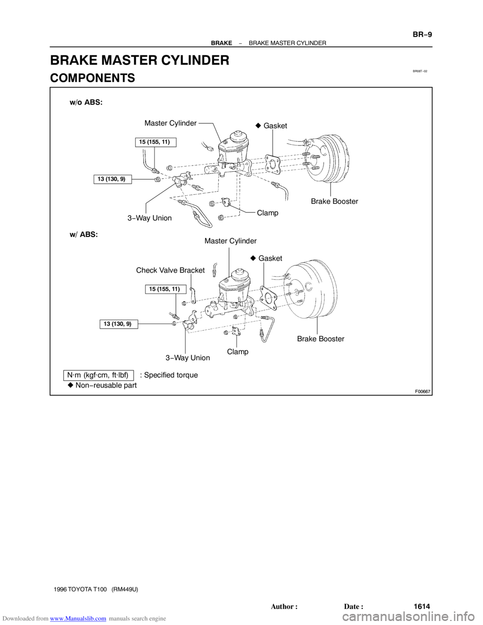
F00667
F00667
w/o ABS:
w/ ABS:Master Cylinder
3−Way UnionBrake Booster � Gasket
Clamp
� Non−reusable partCheck Valve Bracket� Gasket
Brake Booster
Clamp
3−Way Union
N·m (kgf·cm, ft·lbf) : Specified torque
15 (155, 11)
13 (130, 9)
13 (130, 9)
15 (155, 11)
Master Cylinder
− BRAKEBRAKE MASTER CYLINDER
BR−9
1614 Author�: Date�:
1996 TOYOTA T100 (RM449U)
BRAKE MASTER CYLINDER
COMPONENTS
Page 1648 of 2062
Downloaded from www.Manualslib.com manuals search engine BR08U−01
R12875
SST
R12876
− BRAKEBRAKE MASTER CYLINDER
BR−11
1996 TOYOTA T100 (RM449U)
REMOVAL
1. DISCONNECT LEVEL WARNING SWITCH
CONNECTOR
2. TAKE OUT FLUID WITH SYRINGE
NOTICE:
Do not let brake fluid remain on a painted surface. Wash it
off immediately.
3. DISCONNECT BRAKE LINES
Using SST, disconnect the brake lines from the master cylinder
and 3−way union.
SST 09751−36011
4. REMOVE MASTER CYLINDER
(a) Remove the 4 nuts and 3−way union.
Torque: 13 N·m (130 kgf·cm, 9 ft·lbf)
(b) Remove the clamp.
(c) w/ ABS:
Remove the check valve bracket.
(d) Remove the master cylinder and gasket from the brake
booster.
Page 1653 of 2062
Downloaded from www.Manualslib.com manuals search engine BR08Y−01
BR−16
− BRAKEBRAKE MASTER CYLINDER
1996 TOYOTA T100 (RM449U)
INSTALLATION
Installation is in the reverse order of removal (See page BR−11).
1. BEFORE INSTALLATION, ADJUST LENGTH OF BRAKE BOOSTER PUSH ROD
(See page BR−20)
2. AFTER INSTALLATION, FILL BRAKE RESERVOIR WITH BRAKE FLUID. AND BLEED BRAKE
SYSTEM (See page BR−4)
3. CHECK FOR LEAKS, CHECK AND ADJUST BRAKE PEDAL (See page BR−6)
Page 1654 of 2062
Downloaded from www.Manualslib.com manuals search engine BR2237
BR08Z−01
BR2238
GOOD NO GOOD
1st2nd3rd
− BRAKEBRAKE BOOSTER ASSEMBLY
BR−17
1622 Author�: Date�:
1996 TOYOTA T100 (RM449U)
BRAKE BOOSTER ASSEMBLY
ON−VEHICLE INSPECTION
1. OPERATING CHECK
(a) Depress the brake pedal several times with the engine off,
and check that there is no change in the pedal reserve
distance.
(b) Depress the brake pedal and start engine. If the pedal
goes down slightly, operation is normal.
2. AIR TIGHTNESS CHECK
(a) Start the engine and stop it after 1 or 2 minutes. Depress
the brake pedal several times slowly.
If the pedal goes down furthest the 1st time, but gradually rises
after the 2nd or 3rd time, the booster is air tight.
(b) Depress the brake pedal while the engine is running, and
stop it with the pedal depressed. If there is no change in
pedal reserve travel after holding the pedal for 30 se-
conds, the booster is air tight.
Page 1657 of 2062

INSTALLATION
1. INSTALL BRAK")
Downloaded from www.Manualslib.com manuals search engine BR092−01
BR3286
F03521
SST
Gasket
Z03607
SST BR−20
− BRAKEBRAKE BOOSTER ASSEMBLY
1996 TOYOTA T100 (RM449U)
INSTALLATION
1. INSTALL BRAKE BOOSTER
(a) Install the booster and a new gasket.
(b) Install the clevis to the operating rod.
(c) Install and torque the booster installation nuts.
Torque: 13 N·m (130 kgf·cm, 9 ft·lbf)
(d) Install the clevis pin into the clevis and brake pedal, and
install the clip to the clevis pin.
(e) Install the pedal return spring.
2. ADJUST LENGTH OF BOOSTER PUSH ROD
(a) Install a new gasket on the master cylinder.
(b) Set the SST on the gasket, and lower the pin until its tip
slightly touches the piston.
SST 09737−00010
(c) Turn the SST upside down, and set it on the booster.
SST 09737−00010
(d) Measure the clearance between the booster push rod
and pin head (SST).
Clearance: 0 mm (0 in.)
(e) Adjust the booster push rod length until the push rod light-
ly touches the pin head.
3. INSTALL MASTER CYLINDER (See page BR−16)
4. CONNECT VACUUM HOSE TO BRAKE BOOSTER
5. FILL BRAKE RESERVOIR WITH BRAKE FLUID AND
BLEED BRAKE SYSTEM (See page BR−4)
6. CHECK FOR FLUID LEAKAGE
7. CHECK AND ADJUST BRAKE PEDAL
(See page BR−6)
Check and adjust the brake pedal, then tighten the clevis lock
nut.
Torque: 25 N·m (260 kgf·cm, 19 ft·lbf)
8. DO OPERATIONAL CHECK (See page BR−17)
Page 1659 of 2062

1996 TOYOTA T100 (RM449U)
REPLACEMENT
1. REMOVE FRONT WHEEL
Remove the")
Downloaded from www.Manualslib.com manuals search engine BR094−01
BR3082
R04837
BR3312
BR−22
− BRAKEFRONT BRAKE PAD (2WD)
1996 TOYOTA T100 (RM449U)
REPLACEMENT
1. REMOVE FRONT WHEEL
Remove the wheel and temporarily fasten the disc with hub
nuts.
2. INSPECT PAD LINING THICKNESS
Check the pad thickness through the caliper inspection hole
and replace pads if not within specification.
Minimum thickness: 1.0 mm (0.039 in.)
3. LIFT UP CALIPER
(a) Remove the installation bolt.
(b) Lift up the caliper and suspend it securely.
HINT:
Do not disconnect the flexible hose from the caliper.
4. REMOVE THESE PARTS:
�1 ton:
2 anti−squeal springs
�2 brake pads
�2 (1 ton) / 4 (0.5 ton) anti−squeal shims
�2 pad wear indicator plates
�4 pad support plates
NOTICE:
The anti−squeal springs (1 ton) and support plates can be
used again provided that they have sufficient rebound, no
deformation, cracks or wear, and have had all rust, dirt and
foreign particles cleaned off.
5. CHECK DISC THICKNESS AND RUNOUT
(See page BR−30)
6. INSTALL 4 PAD SUPPORT PLATES
7. INSTALL NEW PADS
NOTICE:
When replacing worn pads, the anti−squeal shims and
wear indicator plates must be replaced together with the
pads.
(a) Install a pad wear indicator plate to the pad.
(b) 1 ton:
Install the anti−squeal shim to each pad.
(c) 0.5 ton:
Install the 4 anti−squeal shims to each pad.
HINT:
Apply disc brake grease to both sides of inner anti−squeal
shims (See page BR−21).

REMOVAL
1. DISCONNECT LEVEL WARNING SWITCH
CONN")

INSTALLATION
Installation is in the reverse order of removal (See")