Page 1584 of 2062
Downloaded from www.Manualslib.com manuals search engine SA0HI−01
SA−11 4
− SUSPENSION AND AXLEFRONT UPPER BALL JOINT (4WD)
1996 TOYOTA T100 (RM449U)
INSTALLATION
Installation is in the reverse order of removal (See page SA−11 2).
AFTER INSTALLATION, CHECK ABS SPEED SENSOR SIGNAL (See page DI−321) AND FRONT
WHEEL ALIGNMENT (See page SA−10)
Page 1588 of 2062
Downloaded from www.Manualslib.com manuals search engine SA0HM−01
SA−11 8
− SUSPENSION AND AXLEFRONT LOWER BALL JOINT (2WD)
1996 TOYOTA T100 (RM449U)
INSTALLATION
Installation is in the reverse order of removal (See page SA−11 6).
AFTER INSTALLATION, CHECK ABS SPEED SENSOR SIGNAL (See page DI−321) AND FRONT
WHEEL ALIGNMENT (See page SA−7)
Page 1592 of 2062
Downloaded from www.Manualslib.com manuals search engine SA0HQ−01
SA−122
− SUSPENSION AND AXLEFRONT LOWER BALL JOINT (4WD)
1996 TOYOTA T100 (RM449U)
INSTALLATION
Installation is in the reverse order of removal (See page SA−120).
AFTER INSTALLATION, CHECK ABS SPEED SENSOR SIGNAL (See page DI−321) AND FRONT
WHEEL ALIGNMENT (See page SA−10)
Page 1601 of 2062

Downloaded from www.Manualslib.com manuals search engine SA0HY−07
R05272
R04282
SST
− SUSPENSION AND AXLEREAR AXLE SHAFT
SA−131
1996 TOYOTA T100 (RM449U)
REMOVAL
1. REMOVE REAR WHEEL
Torque: 103 N·m (1,050 kgf·cm, 76 ft·lbf)
2. REMOVE BRAKE DRUM
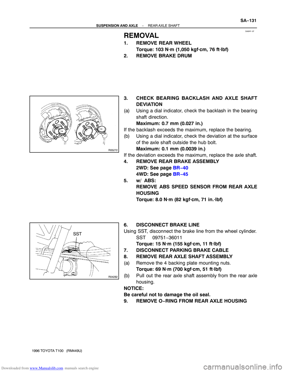
3. CHECK BEARING BACKLASH AND AXLE SHAFT
DEVIATION
(a) Using a dial indicator, check the backlash in the bearing
shaft direction.
Maximum: 0.7 mm (0.027 in.)
If the backlash exceeds the maximum, replace the bearing.
(b) Using a dial indicator, check the deviation at the surface
of the axle shaft outside the hub bolt.
Maximum: 0.1 mm (0.0039 in.)
If the deviation exceeds the maximum, replace the axle shaft.
4. REMOVE REAR BRAKE ASSEMBLY
2WD: See page BR−40
4WD: See page BR−45
5. w/ ABS:
REMOVE ABS SPEED SENSOR FROM REAR AXLE
HOUSING
Torque: 8.0 N·m (82 kgf·cm, 71 in.·lbf)
6. DISCONNECT BRAKE LINE
Using SST, disconnect the brake line from the wheel cylinder.
SST 09751−36011
Torque: 15 N·m (155 kgf·cm, 11 ft·lbf)
7. DISCONNECT PARKING BRAKE CABLE
8. REMOVE REAR AXLE SHAFT ASSEMBLY
(a) Remove the 4 backing plate mounting nuts.
Torque: 69 N·m (700 kgf·cm, 51 ft·lbf)
(b) Pull out the rear axle shaft assembly from the rear axle
housing.
NOTICE:
Be careful not to damage the oil seal.
9. REMOVE O−RING FROM REAR AXLE HOUSING
Page 1603 of 2062

Downloaded from www.Manualslib.com manuals search engine R12256
SST
SA0541
SST
SST
SA0536
SST
SA0539
SST
SA0532
Socket
Wrench
− SUSPENSION AND AXLEREAR AXLE SHAFT
SA−133
1996 TOYOTA T100 (RM449U)
5. INSPECT OUTER OIL SEAL
(a) Check for damage.
(b) Check the oil seal lip for wear or damage.
6. REMOVE OUTER OIL SEAL
Using SST, remove the oil seal.
SST 09308−00010
7. INSPECT REAR AXLE BEARING
Check for wear or damage.
8. REPLACE REAR AXLE BEARING
(a) Using SST and a press, remove the bearing.
SST 09223−56010, 09950−60010 (09951−00560)
(b) Using SST and a press, install a new bearing.
SST 09950−60010 (09951−00610),
09950−70010 (09951−07150)
9. INSTALL NEW OUTER OIL SEAL
Using SST and a hammer, install a new oil seal.
SST 09950−60010 (09951−00610),
09950−70010 (09951−07150)
10. INSPECT BEARING CASE
Check for wear or damage.
11. REPLACE BEARING CASE
(a) Remove the oil seal (outer side) and bearing.
(b) Install nuts to the serration bolts.
(c) Using a hammer, remove the serration bolts and bearing
case.
(d) Position the backing plate on the new bearing case and
using 2 socket wrenches and a press, install the serration
bolts.
(e) Install a new bearing and oil seal (outer side).
Page 1604 of 2062

Downloaded from www.Manualslib.com manuals search engine R04283
SST
R04284
SST
R12939
SSTBearing Side
Z17542SST 122.2 ± 1mm
(4.811 ± 0.039 in.) SA−134
− SUSPENSION AND AXLEREAR AXLE SHAFT
1996 TOYOTA T100 (RM449U)
12. INSPECT OIL SEAL (INNER SIDE)
Check for wear or damage.
13. REPLACE OIL SEAL (INNER SIDE)
(a) Using SST, remove the oil seal.
SST 09308−00010
(b) Using SST and a hammer, install a new oil seal.
SST 09950−60020 (09951−00890),
09950−70010 (09951−07150)
(c) Apply MP grease to the oil seal lip.
14. INSTALL REAR AXLE SHAFT IN BACKING PLATE
(a) Apply MP grease to the oil seal lip.
(b) Install the backing plate and bearing retainer on the rear
axle shaft.
(c) Using SST and a press, install the rear axle shaft into the
backing plate.
SST 09316−60011 (09316−00051)
(d) Using snap ring pliers, install a new snap ring.
15. w/ ABS:
INSTALL ABS SPEED SENSOR ROTOR AND
BEARING RETAINER (DIFFERENTIAL SIDE)
Using SST and a press, install a new sensor rotor and a new
bearing retainer to the axle shaft.
SST 09316−60011 (09316−00051)
Standard length: 122.2 ± 1 mm (4.811 ± 0.039 in.)
Page 1605 of 2062
Downloaded from www.Manualslib.com manuals search engine SA0I0−01
− SUSPENSION AND AXLEREAR AXLE SHAFT
SA−135
1996 TOYOTA T100 (RM449U)
INSTALLATION
Installation is in the reverse order of removal (See page SA−131).
AFTER INSTALLATION, BLEED BRAKE SYSTEM (See page BR−4), CHECK FOR LEAKS AND ABS
SPEED SENSOR SIGNAL (See page DI−321)
Page 1610 of 2062

Downloaded from www.Manualslib.com manuals search engine SA259−01
W00493
30 mm
(1.18 in.)
R04321
R04322
R04323
R04463
SA−140
− SUSPENSION AND AXLEREAR DIFFERENTIAL CARRIER
1996 TOYOTA T100 (RM449U)
DISASSEMBLY
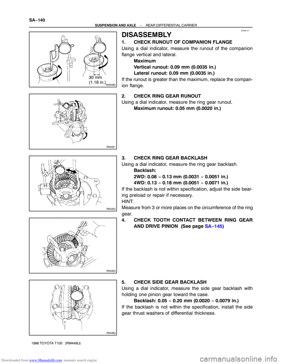
1. CHECK RUNOUT OF COMPANION FLANGE
Using a dial indicator, measure the runout of the companion
flange vertical and lateral.
Maximum
Vertical runout: 0.09 mm (0.0035 in.)
Lateral runout: 0.09 mm (0.0035 in.)
If the runout is greater than the maximum, replace the compan-
ion flange.
2. CHECK RING GEAR RUNOUT
Using a dial indicator, measure the ring gear runout.
Maximum runout: 0.05 mm (0.0020 in.)
3. CHECK RING GEAR BACKLASH
Using a dial indicator, measure the ring gear backlash.
Backlash:
2WD: 0.08 − 0.13 mm (0.0031 − 0.0051 in.)
4WD: 0.13 − 0.18 mm (0.0051 − 0.0071 in.)
If the backlash is not within specification, adjust the side bear-
ing preload or repair if necessary.
HINT:
Measure from 3 or more places on the circumference of the ring
gear.
4. CHECK TOOTH CONTACT BETWEEN RING GEAR
AND DRIVE PINION (See page SA−145)
5. CHECK SIDE GEAR BACKLASH
Using a dial indicator, measure the side gear backlash with
holding one pinion gear toward the case.
Backlash: 0.05 − 0.20 mm (0.0020 − 0.0079 in.)
If the backlash is not within the specification, install the side
gear thrust washers of differential thickness.