Page 208 of 1354

QUARTER PANEL
RH:
LH:
1. Cut and join the parts at the location shown above.
HOW TO USE THIS MANUAL
Each repair method description provided in Section RE of")
mm in.
150
2505.91
9.84
QUARTER PANEL (CUT)
QUARTER PANEL
RH:
LH:
1. Cut and join the parts at the location shown above.
HOW TO USE THIS MANUAL
Each repair method description provided in Section RE of this manual comprises two pages, divided into 2
blocks (REMOVAL AND INSTALLATION) and includes illustrations to facilitate body repair.
RE-10
BODY PANEL REPLACEMENT
REMOVAL
[Cut and Join Location]
250 mm
Cut and Join Location
Cut and Join Location
(Cut Location for
Supply Parts)
Cut and Join Location
(Cut and Join Location )
Braze
REPLACEMENT PARTS AND METHOD
(CUT)
Replacement method
(ASSY) Assembly replacement. . . . .
(CUT) Major cutting (less than 1/2 of parts used). . . . . .
(CUT-H) Half cutting (about 1/2 of parts used). . . .
(CUT-P) Partial cutting (most of parts used). . . .
Replacement Parts
PARTS LOCATION
REMOVAL DIAGRAM
Describes in detail removal of the damaged parts involving repair by cutting.
REMOVAL GUIDE
Provides additional information to more efficiently help you perform the removal.
INTRODUCTIONINœ2
Page 212 of 1354
Airbag SensorInflator Sensor Lock Release BoltBagSteering Wheel PadSteering Wheel Bolt Cap Airbag SensorInflatorBag
HANDLING PRECAUTIONS ON RELATED COMPONENTS
1. SRS AIRBAG
The TOYOTA RAV4 is equipped with an SRS (Supplemental Restraint System) airbag as an option.
Failure to carry out service operations in the correct sequence could cause the airbag system to unexœ
pectedly deploy during servicing, possibly leading to a serious accident.
Further, if a mistake is made in servicing the airbag system, it is possible the airbag may fail to operate
when required.
Before performing servicing (including removal or installation of parts, inspection or replacement), be
sure to read the following items carefully, then follow the correct procedure described in the repair
manual for relevant model.
Location of Components
INTRODUCTIONINœ6
Page 213 of 1354
 section
Rear Wheels
Suspension and Axle (SA) section
1. Never disassemble the steering wheel p")
Component to be alignedSection of repair manual
for relevant model
Front Wheels
Suspension and Axle (SA) section
Rear Wheels
Suspension and Axle (SA) section
1. Never disassemble the steering wheel pad assembly.
2. Do not subject the steering wheel pad to shocks or bring magnets close to it.
3. Do not expose the steering wheel pad to high temperatures or fire.
4. If grease, cleaner, oil or water gets on the steering wheel pad, promptly wipe it off with a dry cloth.
5. Do not drop the steering wheel pad. Never use a steering wheel pad which has been dropped.
6. Never install the steering wheel and pad in another vehicle.
7. When the steering wheel pad is removed, store it on a stable, flat place with the pad surface facing upœ
wards. Never place anything on top of the pad.
8. When work on the vehicle will produce too strong a shock, first loosen the sensor lock release bolt until
it turns freely and perform the work after sensor lock occurs.
9. Even in cases where the vehicle is in a low-impact accident where the airbag is not activated, always
check the pad surface and airbag sensor part. If dents, cracks or deformation is visible, replace the airœ
bag with a new assembly.
10. When disposing of the vehicle or steering wheel, always deploy the airbag first.
11. The deployed inflator inside the steering wheel pad is hot, so dispose of it after it has been cooled by
atmospheric air. Never apply water to cool it down.
2. BRAKE SYSTEM
The brake system is one of the most important safety components. Always follow the directions and
notes given in section BR of the repair manual for the relevant model year when handling brake system
parts.
3. DRIVE TRAIN AND CHASSIS
The drive train and chassis are components that can have great effects on the running performance
and vibration resistance of the vehicle. After installing components in the sections listed in the table
below, perform alignments to ensure correct mounting angles and dimensions. Particularly accurate
repair of the body must also be done to ensure correct alignment.
HINT: Correct procedures and special tools are required for alignment. Always follow the directions
given in the repair manual for the relevant model during alignment and section DI of this manual.
INTRODUCTIONINœ7
Page 214 of 1354
 Door Look Control RelayA/C Amplifier J/B No. 3
4. ECU (ELECTRONIC CONTROL UNIT)
Locations of ECUs
Many ECUs a")
Fuse BlockEngine ECU R/B No. 5 J/B No. 1J/B No. 4 ABS ECUDaytime Running
Light Relay (*1) Door Look Control RelayA/C Amplifier J/B No. 3
4. ECU (ELECTRONIC CONTROL UNIT)
Locations of ECUs
Many ECUs are mounted in this vehicle.
Take the following precautions during body repair to prevent damage to the ECUs.
�Before starting electric welding operations, disconnect the negative (-) terminal cable from the battery.
When the negative (-) terminal cable is disconnected from the battery, memory of the clock and audio
systems will be cancelled. So before starting work, make a record of the contents memorized by each
memory system. Then when work is finished, reset the clock and audio systems as before.
When the vehicle has tilt and telescopic steering, power seat and outside rear view mirror, which are all
equipped with memory function, it is not possible to make a record of the memory contents.
So when the operation is finished, it will be necessary to explain this fact to the customer, and request
the customer to adjust the features and reset the memory.
�Do not expose the ECUs to ambient temperatures above 80°C (176°F).
NOTICE: If it is possible the ambient temperature may reach 80 °C (176 °F) or more, remove the ECUs
from the vehicle before starting work.
�Be careful not to drop the ECUs and not to apply physical shocks to them.
4. COMPONENTS ADJACENT TO THE BODY PANELS
Various types of component parts are mounted directly on or adjacently to the body panels.
Strictly observe the following precautions to prevent damaging these components and the body panels
during handling.
�Before repairing the body panels, remove their components or apply protective covers over the comœ
ponents.
�Before prying components off using screwdriver or a scraper, etc., attach protective tape to the tool
tip or blade to prevent damaging the components and the body paint.
�Before removing components from the outer surface of the body, attach protective tape to the body to
ensure no damage to painted areas.
HINT: Apply touch-up paint to any damaged paint surfaces.
�Before drilling or cutting sections, make sure that there are no wires, etc. on the reverse side.
INTRODUCTIONINœ8
Page 221 of 1354
ABS Antilock Brake System
A/C Air Conditioner
assy assembly
ECT Electronic Controlled Transmission
ECU Electronic Control Unit
e.g. Exempli Gratia (for Example)
Ex. Except
FWD Front Wheel Drive Vehicles
4WD Four Wheel Drive Vehicles
in. inch
LH Left-hand
LHD Left-hand Drive
MIG Metal Inert Gas
M/Y Model Year
PPS Progressive Power Steering
RH Right-hand
RHD Right-hand Drive
SRS Supplemental Restraint System
w/ with
w/o without
ABBREVIATIONS USED IN THIS MANUAL
For convenience, the following abbreviations are used in this
manual.
INTRODUCTIONINœ15
Page 226 of 1354
HINT: For symbols, capital letters indicate right side of vehicle,
small letters indicate left side of vehicle (Seen from rear).
mm (in.)
(Three-Dimensional Distance)
Hole dia.
6 (0.24) nut
7.5y7.5 (0.295y0.295)
16 (0.63) Name
Back door stopper installation nut-lower
Rear floor finish plate installation hole
Shock absorber installation hole
Roof side rail assembly mark Symbol
c
D, d
E, e
F, f Hole dia.
13 (0.51)
8 (0.31) nut
13 (0.51) Name
Back door opening frame / Roof panel adjoining
portion
Back door hinge installation hole-upper
B
Back door lock striker installation nut-upper
C
Back door hinge installation hole-lower Symbol
A, a
b
BODY OPENING AREAS (REAR View)
BODY DIMENSIONSDIœ6
Page 279 of 1354
 or more
Release Point
Full Stroke
End Position CL−2
−")
Q08873
Push Rod Play
Adjust Point
Pedal Height
Adjust Point
Push Rod
Play
Pedal HeightCL04G−02
CL0042
Pedal Freeplay
CL0512
25 mm (0.98 in.) or more
Release Point
Full Stroke
End Position CL−2
− CLUTCHCLUTCH PEDAL
1996 RAV4 (RM447U)
CLUTCH PEDAL
INSPECTION
1. CHECK PEDAL HEIGHT IS CORRECT
Pedal height from asphalt sheet:
157.6 − 167.6 mm (6.205 − 6.598 in.)
2. IF NECESSARY, ADJUST PEDAL HEIGHT
Loosen the lock nut and turn the stopper bolt until the height is
correct. Tighten the lock nut.
3. CHECK PEDAL FREEPLAY AND PUSH ROD PLAY
(a) Push in on the pedal until the beginning of clutch resis-
tance is felt.
Pedal freeplay: 5.0−15.0 mm (0.197−0.591 in.)
(b) Gently push on the pedal until the resistance begins to in-
crease a little.
Push rod play at pedal top:
1.0−5.0 mm (0.039−0.197 in.)
4. IF NECESSARY, ADJUST PEDAL FREEPLAY AND
PUSH ROD PLAY
(a) Loosen the lock nut and turn the push rod until the free-
play and push rod play are correct.
(b) Tighten the lock nut.
(c) After adjusting the pedal freeplay, check the pedal height.
(d) Connect the air duct and install the lower finish panel.
5. INSPECT CLUTCH RELEASE POINT
(a) Pull the parking brake lever and install wheel stopper.
(b) Start the engine and idle the engine.
(c) Without depressing the clutch pedal, slowly shift the shift
lever into the reverse position until the gears contact.
(d) Gradually depress the clutch pedal and measure the
stroke distance from the point the gear noise stops (re-
lease point) up to the full stroke end position.
Standard distance:
25 mm (0.98 in.) or more
(From pedal stroke end position to release point)
If the distance is not as specified.
�Inspect pedal height.
�Inspect push rod play and pedal freeplay.
�Bleed the clutch line.
�Inspect the clutch cover and disc.
Page 282 of 1354
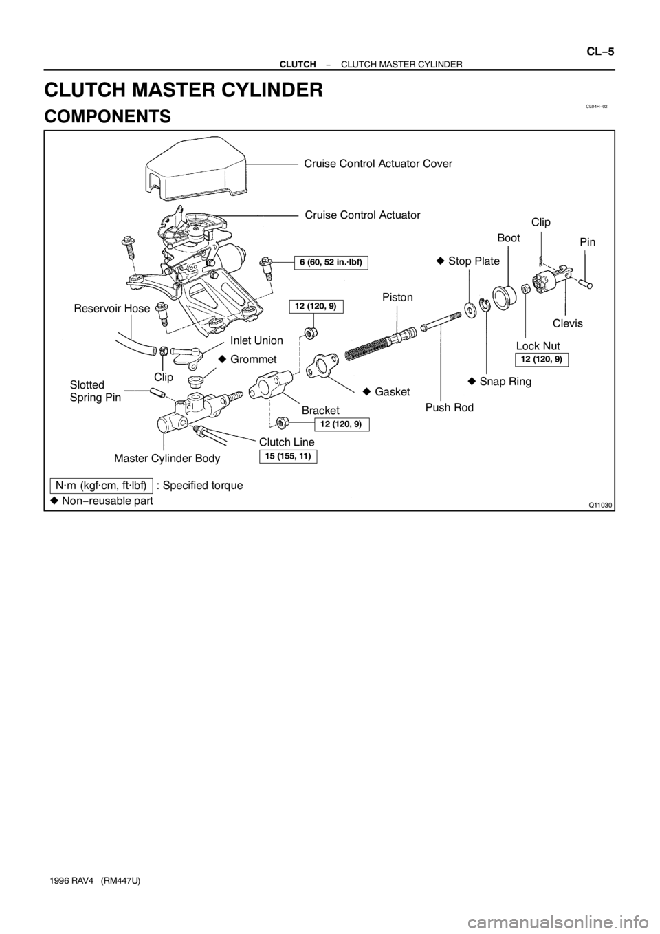
CL04H−02
Q11030
Cruise Control Actuator Cover
N·m (kgf·cm, ft·lbf) : Specified torqueMaster Cylinder Body Reservoir Hose
Slotted
Spring PinInlet Union
� Grommet
Clutch Line
BracketBootClip
Clevis
Lock Nut
� Gasket Clip
� Snap Ring � Stop Plate
Piston
� Non−reusable part
6 (60, 52 in.·lbf)
12 (120, 9)
15 (155, 11)
12 (120, 9)
Cruise Control Actuator
Pin
Push Rod
12 (120, 9)
− CLUTCHCLUTCH MASTER CYLINDER
CL−5
1996 RAV4 (RM447U)
CLUTCH MASTER CYLINDER
COMPONENTS


Ex. Except
FWD Front Wheel Drive V")
.
mm (in.)
(Three-Dimensional Distance)
Hole dia.
6 (0.24) nut
7.5y7.5 (0")