Page 1004 of 1354

MX05S−01
Q09031
B
A
C
FED A
A
C
Q08759
No.1
No.2 No.0
No.0
− MANUAL TRANSAXLEMANUAL TRANSAXLE UNIT (4WD)
MX−9
1996 RAV4 (RM447U)
REMOVAL
1. REMOVE TRANSAXLE WITH ENGINE
(See page EM−80)
2. REMOVE TRANSAXLE CASE PROTECTOR
Remove the 2 bolts and transaxle case protector.
Torque: 25 N·m (250 kgf·cm, 18 ft·lbf)
3. REMOVE STARTER
(a) Disconnect the connector and wire from the starter.
(b) Remove the 2 bolts and starter.
Torque: 39 N·m (400 kgf·cm, 29 ft·lbf)
4. DISCONNECT DIFFERENTIAL LOCK INDICATOR
SWITCH, BACK−UP LIGHT SWITCH AND VEHICLE
SPEED SENSOR CONNECTORS
5. REMOVE TRANSFER VACUUM ACTUATOR BRACK-
ET
Remove the 4 bolts and bracket.
Torque: 37 N·m (380 kgf·cm, 27 ft·lbf)
6. REMOVE TRANSFER VACUUM ACTUATOR AS-
SEMBLY
(a) Disconnect the 4 solenoid hoses from the transfer vacu-
um actuator assembly.
NOTICE:
At the time of installation, please refer to the following item.
Check that the hose No.0, No.1 and No.2 are securely
installed to the solenoid.
(b) Remove the 2 bolts and transfer vacuum actuator assem-
bly.
Torque: 37 N·m (380 kgf·cm, 27 ft·lbf)
7. REMOVE RIGHT TRANSFER STIFFENER PLATE
Remove the 5 bolts and right transfer stiffener plate.
Torque: 37 N·m (380 kgf·cm, 27 ft·lbf)
8. REMOVE CENTER TRANSFER STIFFENER PLATE
Remove the 3 bolts and center transfer stiffener plate.
Torque: 37 N·m (380 kgf·cm, 27 ft·lbf)
9. REMOVE STIFFENER PLATE
Remove the 2 bolts and stiffener plate.
Torque: 37 N·m (380 kgf·cm, 27 ft·lbf)
10. REMOVE TRANSAXLE FROM ENGINE
(a) Remove the 9 transaxle mounting bolts from the engine.
Torque:
Bolt A: 64 N·m (650 kgf·cm, 47 ft·lbf)
Bolt B: 35 N·m (360 kgf·cm, 26 ft·lbf)
Bolt C: 29 N·m (300 kgf·cm, 22 ft·lbf)
Bolt D: 46 N·m (470 kgf·cm, 34 ft·lbf)
Bolt E: 25 N·m (250 kgf·cm, 18 ft·lbf)
Bolt F: 9.0 N·m (95 kgf·cm, 78 in.·lbf)
Page 1070 of 1354

− MANUAL TRANSAXLEDIFFERENTIAL LOCKING SYSTEM (4WD)
MX−75
1996 RAV4 (RM447U)
3. INSPECT DIFFERENTIAL LOCK CONTROL SOLE-
NOID
Inspect the differential lock control solenoid.
(1) Disconnect the connector from the solenoid No.1
and No.2.
(2) Check continuity to each port when battery positive
voltage is applied and not applied to the connector
terminals of the solenoid No.1 and No.2.
Solenoid No.1
ConditionPort
Battery positive voltageE1 − Air
No voltageG − E1
Solenoid No.2
ConditionPort
Battery positive voltageF − E2
No voltageE2 − Air
4. INSPECT TRANSFER VACUUM ACTUATOR
(a) Vacuum Tank:
Inspect the transfer vacuum tank.
(1) Disconnect the solenoid hose No.0, No.2 and No.3
from the solenoid.
(2) Fill in the No.3 hose with a plug.
(3) Check that the indicator needle remains steady
when a vacuum of 500 mmHg (19.685 in.Hg) is ap-
plied to the hose No.0.
Standard:
Indicator falls 45 mmHg (1.772 in.Hg) or less during 15
seconds.
(b) Diaphragm (Lock Side):
Inspect the transfer vacuum tank.
(1) Disconnect the solenoid hose No.1 and No.2 from
the solenoid.
(2) Check that the indicator needle remains steady
when a vacuum of 500 mmHg (19.685 in.Hg) is ap-
plied to the hose No.1.
Standard:
Indicator falls 45 mmHg (1.772 in.Hg) or less during 15
seconds.
Page 1071 of 1354
MX−76
− MANUAL TRANSAXLEDIFFERENTIAL LOCKING SYSTEM (4WD)
1996 RAV4 (RM447U)
(c) Diaphragm (Free Side):
Inspect the transfer vacuum tank.
(1) Disconnect the solenoid hose No.0, No.1, No.2 and
No.3 from the solenoid.
(2) Fill in the No.3 hose with a plug.
(3) Check that the indicator needle remains steady
when a vacuum of 500 mmHg (19.685 in.Hg) are
applied to the hose No.0 and No.2.
Standard:
Indicator falls 45 mmHg (1.772 in.Hg) or less during 15
seconds.
NOTICE:
Apply vacuum simultaneously to the hose No.0 and hose
No.2.
(4) Reinstall the removed hoses to the solenoid.
NOTICE:
Check that the hose No.0, No.1, No.2 and No.3 are securely
installed to the solenoid.
Page 1233 of 1354

SF0QI−03
S01903
S01939
(1)
(2)
S01827
S01949
Disconnect
Spacer
− SFIINJECTOR
SF−19
1996 RAV4 (RM447U)
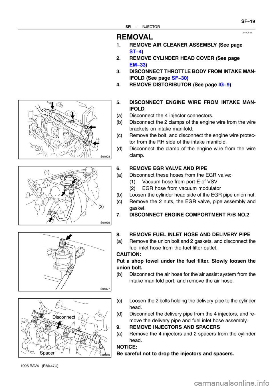
REMOVAL
1. REMOVE AIR CLEANER ASSEMBLY (See page
ST−4)
2. REMOVE CYLINDER HEAD COVER (See page
EM−33)
3. DISCONNECT THROTTLE BODY FROM INTAKE MAN-
IFOLD (See page SF−30)
4. REMOVE DISTORIBUTOR (See page IG−9)
5. DISCONNECT ENGINE WIRE FROM INTAKE MAN-
IFOLD
(a) Disconnect the 4 injector connectors.
(b) Disconnect the 2 clamps of the engine wire from the wire
brackets on intake manifold.
(c) Remove the bolt, and disconnect the engine wire protec-
tor from the RH side of the intake manifold.
(d) Disconnect the clamp of the engine wire from the wire
clamp.
6. REMOVE EGR VALVE AND PIPE
(a) Disconnect these hoses from the EGR valve:
(1) Vacuum hose from port E of VSV
(2) EGR hose from vacuum modulator
(b) Loosen the cylinder head side of the EGR pipe union nut.
(c) Remove the 2 nuts, the EGR valve, pipe assembly and
gasket.
7. DISCONNECT ENGINE COMPORTMENT R/B NO.2
8. REMOVE FUEL INLET HOSE AND DELIVERY PIPE
(a) Remove the union bolt and 2 gaskets, and disconnect the
fuel inlet hose from the fuel filter outlet.
CAUTION:
Put a shop towel under the fuel filter. Slowly loosen the
union bolt.
(b) Disconnect the air hose for the air assist system from the
intake manifold port, and remove the air hose.
(c) Loosen the 2 bolts holding the delivery pipe to the cylinder
head.
(d) Disconnect the delivery pipe from the 4 injectors, and re-
move the delivery pipe and fuel inlet hose assembly.
9. REMOVE INJECTORS AND SPACERS
(a) Remove the 4 injectors and 2 spacers from the cylinder
head.
NOTICE:
Be careful not to drop the injectors and spacers.
Page 1241 of 1354

S01898
SF0QO−03
S01946
P
E
R
S00037
Ohmmeter
Throttle Position Sensor
VC
VTA
E2
S01901
Disconnect
Plug
− SFITHROTTLE BODY
SF−27
1996 RAV4 (RM447U)
THROTTLE BODY
ON−VEHICLE INSPECTION
1. INSPECT THROTTLE BODY
(a) Check that the throttle linkage moves smoothly.
(b) Check the vacuum at each port.
�Start the engine.
�Check the vacuum with your finger.
Port nameAt idleOther than idle
PNo vacuumVacuum
ENo vacuumVacuum
RNo vacuumNo vacuum
2. INSPECT THROTTLE POSITION SENSOR
(a) Apply vacuum to the throttle opener.
(b) Disconnect the sensor connector.
(c) Using an ohmmeter, measure the resistance between
each terminal.
Clearance between
lever and stop screwBetween
terminalsResistance
0 mm (0 in.)VTA − E20.2 − 5.7 kΩ
Throttle valve fully
openVTA − E22.0 − 10.2 kΩ
−VC − E22.5 − 5.9 kΩ
(d) Reconnect the sensor connector.
3. INSPECT AND ADJUST THROTTLE OPENER
4. WARM UP ENGINE
Allow the engine to warm up to normal operating temperature.
5. CHECK IDLE SPEED
Idle speed: 700 ± 50 rpm
6. CHECK AND ADJUST THROTTLE OPENER SETTING
SPEED
(a) Disconnect the vacuum hose from the throttle opener,
and plug the hose end.
(b) Maintain the engine at 2,500 rpm.
(c) Release the throttle valve.
(d) Check that the throttle opener is set.
Throttle opener setting speed:
1,300 − 1,500 rpm (w/ cooling fan OFF)
Page 1242 of 1354
S01945
Throttle Opener
Adjusting Screw
2.5 mm Hexagon Wrench SF−28
− SFITHROTTLE BODY
1996 RAV4 (RM447U)
(e) Adjust the throttle opener setting speed by turning the
throttle opener adjusting screw.
(f) Reconnect the vacuum hose to the throttle opener.
Page 1244 of 1354

SF0QQ−03
S01905
(4) (3)
(2)
(1)
S01907
A
B
Protrusion
(Bolt: Type A)
(Nut: Type B)B A
S01902
(1)
(3)(2) SF−30
− SFITHROTTLE BODY
1996 RAV4 (RM447U)
REMOVAL
1. DRAIN ENGINE COOLANT
2. A/T:
DISCONNECT THROTTLE CABLE FROM THROTTLE
BODY
3. DISCONNECT ACCELERATOR CABLE FROM
THROTTLE BODY
4. REMOVE AIR CLEANER CAP ASSEMBLY (See page
ST−4)
5. REMOVE THROTTLE BODY
(a) Disconnect the throttle position sensor connector.
(b) Disconnect the IAC valve connector.
(c) Disconnect these hoses from the throttle body:
(1) PCV hose from air tube
(2) Vacuum hose from port ”R” of EGR vacuum modu-
lator
(3) Vacuum hose from port ”P” of EGR vacuum modu-
lator
(4) EVAP hose from chacoal canister
(d) Remove the 4 bolts (Type A) or the 2 bolts, 2 nuts (Type
B) and gasket, and diaconnect the throttle body from the
intake manifold.
Torque: 19 N·m (195 kgf·cm, 14 ft·lbf)
HINT:
At the time of installation, plaese refer to the following items.
�Place a new gasket on the intake chamber, facing the pro-
trusion downward.
�Each bolt is indicated in the illustration (Type A).
Bolt length:
A: 40 mm (1.57 in.)
B: 55 mm (2.17 in.)
(e) Disconnect these hoses from the throttle body:
(1) Water bypass hose from water outlet
(2) Water bypass hose from water bypass pipe
(3) Air hose from intake manifold
Page 1245 of 1354

SF1QE−01
S01897
S01911Vacuum Throttle Lever
Throttle
Stop
Screw
No Clearance
P00025
VC
VTA
IDL
E2
VC VTA IDL E2
S01899
− SFITHROTTLE BODY
SF−31
1996 RAV4 (RM447U)
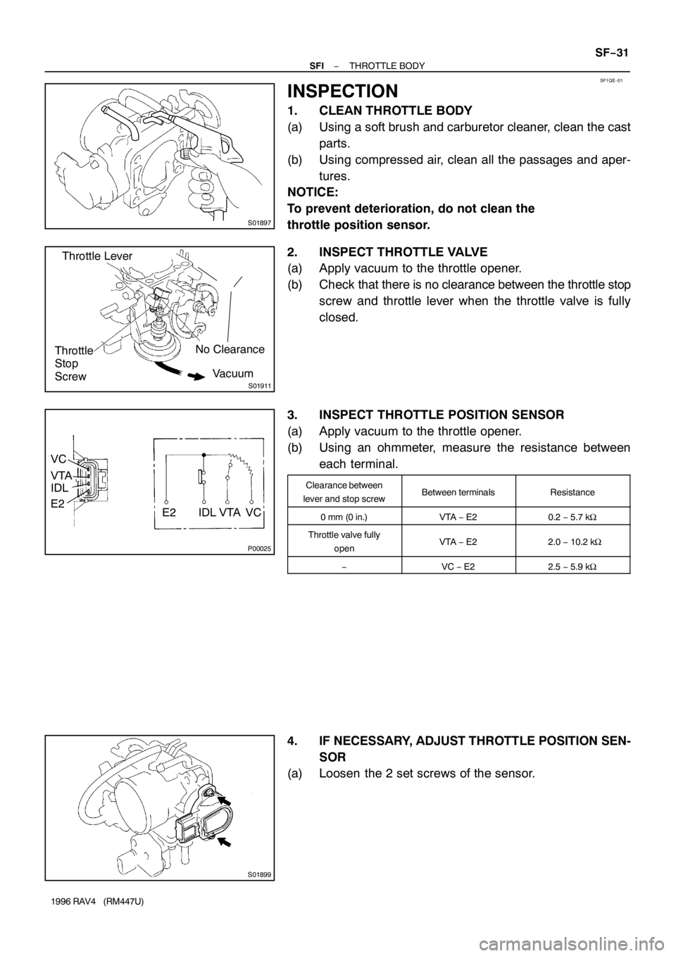
INSPECTION
1. CLEAN THROTTLE BODY
(a) Using a soft brush and carburetor cleaner, clean the cast
parts.
(b) Using compressed air, clean all the passages and aper-
tures.
NOTICE:
To prevent deterioration, do not clean the
throttle position sensor.
2. INSPECT THROTTLE VALVE
(a) Apply vacuum to the throttle opener.
(b) Check that there is no clearance between the throttle stop
screw and throttle lever when the throttle valve is fully
closed.
3. INSPECT THROTTLE POSITION SENSOR
(a) Apply vacuum to the throttle opener.
(b) Using an ohmmeter, measure the resistance between
each terminal.
Clearance between
lever and stop screwBetween terminalsResistance
0 mm (0 in.)VTA − E20.2 − 5.7 kΩ
Throttle valve fully
openVTA − E2 2.0 − 10.2 kΩ
−VC − E22.5 − 5.9 kΩ
4. IF NECESSARY, ADJUST THROTTLE POSITION SEN-
SOR
(a) Loosen the 2 set screws of the sensor.