Page 678 of 1354
EM0EK−01
EM−12
− ENGINE MECHANICALIDLE SPEED
1996 RAV4 (RM447U)
IDLE SPEED
INSPECTION
1. INITIAL CONDITIONS
(a) Engine at normal operating temperature
(b) Air cleaner installed
(c) All pipes and hoses of air induction system connected
(d) All vacuum lines properly connected
(e) SFI system wiring connectors fully plugged
(f) All operating accessories switched OFF
(g) Ignition timing check correctly
(h) Transmission in neutral position
(i) Air conditioning switched OFF
2. CONNECT TOYOTA HAND−HELD TESTER OR OBD II SCAN TOOL (See page EM−11)
3. INSPECT IDLE SPEED
(a) Race the engine speed at 2,500 rpm for approx. 90 seconds.
(b) Check the idle speed.
Idle speed (w/ Cooling fan OFF): 750 ± 50 rpm
If the idle speed is not as specified, check the IAC valve and air intake system.
4. DISCONNECT TOYOTA HAND−HELD TESTER OR OBD II SCAN TOOL
Page 701 of 1354

S01560
(3)(1)
(2)
S01806
S01644
S01791
− ENGINE MECHANICALCYLINDER HEAD
EM−35
1996 RAV4 (RM447U)
17. DISCONNECT HOSES AND GROUND STRAP
(a) Disconnect the vacuum sensor hose from the gas filter on
intake manifold.
(b) Disconnect the brake booster vacuum hose from the in-
take manifold.
(c) Disconnect the ground strap from the intake manifold.
18. DISCONNECT FUEL INLET HOSE FROM FUEL FIL-
TER
Remove the union bolt and 2 gaskets, and disconnect the inlet
hose from the fuel filter.
19. REMOVE EGR VALVE AND VACUUM MODULATOR
(a) Disconnect the 2 vacuum hoses from the VSV for the
EGR.
(b) Disconnect the vacuum modulator from the clamp on the
intake manifold.
(c) Loosen the union nut of the EGR pipe, and remove the 2
nuts, the EGR valve, vacuum modulator, vacuum hoses
assembly and gasket.
20. REMOVE INTAKE MANIFOLD STAY
Remove the 2 bolts and intake manifold stay.
21. A/T only:
DISCONENCT A/T THROTTLE CONTROL CABEL
FROM INTAKE MANIFORD
Disconnect the control cable from the clamp on the rear side of
the intake manifold.
22. DISCONNECT PS IDLE−UP AIR HOSES FROM AIR
TUBE
23. DISCONNECT KNOCK SENSOR CONNECTOR
24. DISCONNECT GROUND CABLE
Remove the bolt, and disconnect the ground cable from the in-
take manifold.
25. REMOVE VSV FOR EGR (See page SF−42)
26. REMOVE CYLINDER HEAD COVER
(a) Remove the 2 bolts and accelerator cable bracket.
(b) Disconnect the PCV hose from the intake manifold.
Page 727 of 1354

S01791
S01644
S01806
− ENGINE MECHANICALCYLINDER HEAD
EM−61
1996 RAV4 (RM447U)
(i) Connect the PCV hose to the intake manifold.
(j) Install the accelerator cable bracket with the 2 bolts.
17. INSTALL VSV FOR EGR (See page SF−42)
18. CONNECT GROUND CABLE
Connect the ground cable to the intake manifold with the bolt.
19. CONNECT KNOCK SENSOR CONNECTOR
20. CONNECT PS IDLE−UP AIR HOSES TO AIR TUBE
21. A/T only:
CONNECT A/T THROTTLE CONTROL CABLE TO IN-
TAKE MANIFOLD
Connect the control cable to the clamp on the rear side of the
intake manifold.
22. INSTALL INTAKE MANIFOLD STAY
Install the intake manifold stay with the 2 bolts.
Torque: 42 N·m (425 kgf·cm, 31 ft·lbf)
23. INSTALL EGR VALVE AND VACUUM MODULATOR
(a) Install a new gasket and the EGR valve with the union nut
and 2 nuts.
Torque:
13 N·m (130 kgf·cm, 9 ft·lbf) for nut
59 N·m (600 kgf·cm, 43 ft·lbf) for union nut
(b) Install the vacuum modulator to the clamp on the intake
manifold.
(c) Connect the 2 vacuum hoses to the VSV for the EGR.
24. CONNECT FUEL INLET HOSE TO FUEL FILTER
Connect the inlet hose with 2 new gaskets and the union bolt.
Torque: 29 N·m (300 kgf·cm, 22 ft·lbf)
Page 728 of 1354

S01560
(1)
(2)
(3)
P15451
ConnectNew
New
Gasket
O−Ring
S01594
S01368
EM−62
− ENGINE MECHANICALCYLINDER HEAD
1996 RAV4 (RM447U)
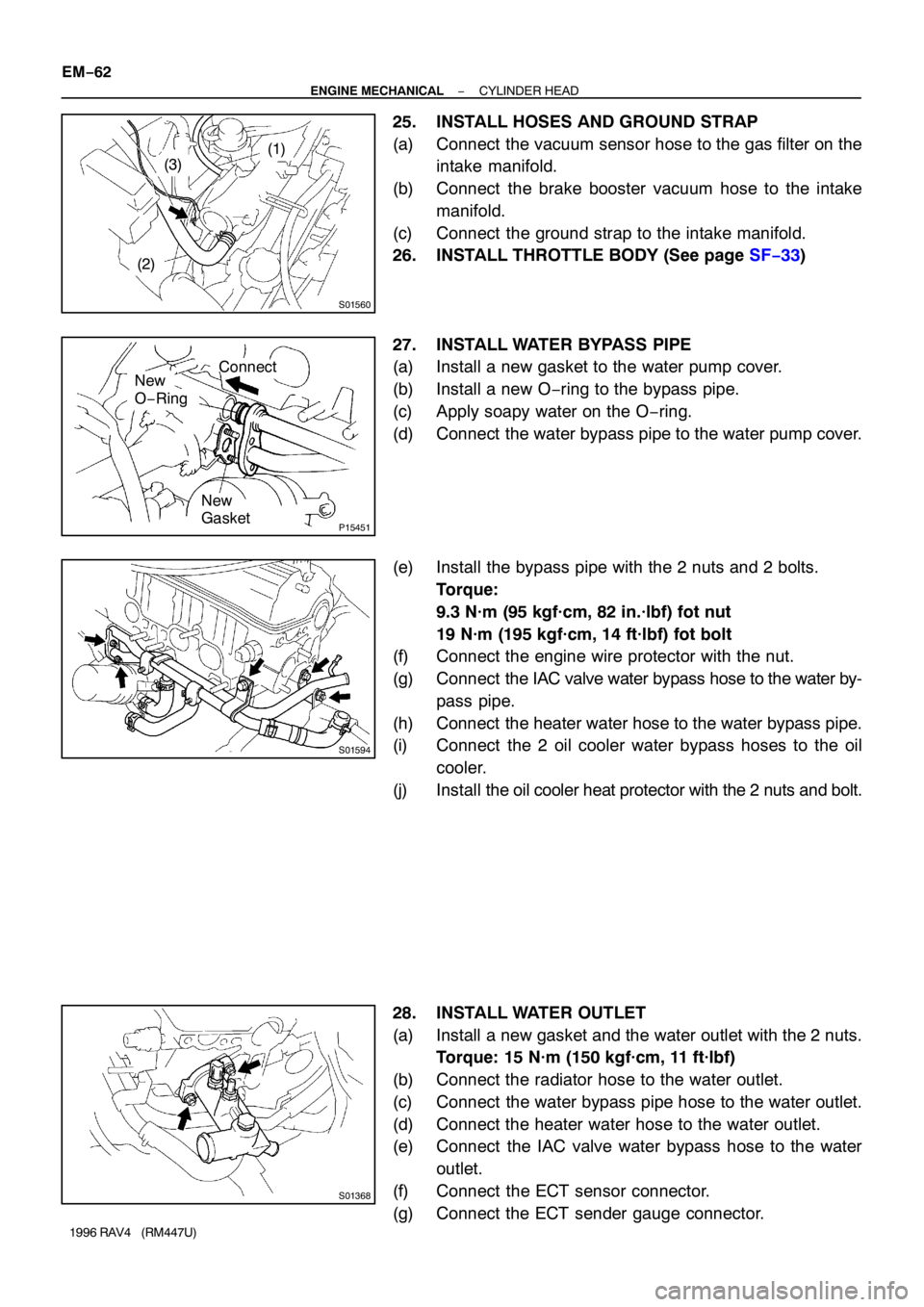
25. INSTALL HOSES AND GROUND STRAP
(a) Connect the vacuum sensor hose to the gas filter on the
intake manifold.
(b) Connect the brake booster vacuum hose to the intake
manifold.
(c) Connect the ground strap to the intake manifold.
26. INSTALL THROTTLE BODY (See page SF−33)
27. INSTALL WATER BYPASS PIPE
(a) Install a new gasket to the water pump cover.
(b) Install a new O−ring to the bypass pipe.
(c) Apply soapy water on the O−ring.
(d) Connect the water bypass pipe to the water pump cover.
(e) Install the bypass pipe with the 2 nuts and 2 bolts.
Torque:
9.3 N·m (95 kgf·cm, 82 in.·lbf) fot nut
19 N·m (195 kgf·cm, 14 ft·lbf) fot bolt
(f) Connect the engine wire protector with the nut.
(g) Connect the IAC valve water bypass hose to the water by-
pass pipe.
(h) Connect the heater water hose to the water bypass pipe.
(i) Connect the 2 oil cooler water bypass hoses to the oil
cooler.
(j) Install the oil cooler heat protector with the 2 nuts and bolt.
28. INSTALL WATER OUTLET
(a) Install a new gasket and the water outlet with the 2 nuts.
Torque: 15 N·m (150 kgf·cm, 11 ft·lbf)
(b) Connect the radiator hose to the water outlet.
(c) Connect the water bypass pipe hose to the water outlet.
(d) Connect the heater water hose to the water outlet.
(e) Connect the IAC valve water bypass hose to the water
outlet.
(f) Connect the ECT sensor connector.
(g) Connect the ECT sender gauge connector.
Page 736 of 1354

S01432
S01285
S01347
EM−70
− ENGINE MECHANICALENGINE UNIT
1996 RAV4 (RM447U)
22. DISCONNECT CONNECTORS, CORD, STRAP AND
HOSES
(a) Disconnect the vapor pressure sensor connector.
(b) Disconnect the igniter connector.
(c) Disconnect the ignition coil connector.
(d) Disconnect the noise filter connector.
(e) Disconnect the high−tension cord from the ignition coil.
(f) Disconnect the MAP sensor connector.
(g) Disconnect the MAP sensor vacuum hose from the gas
filter on the intake manifold.
(h) Disconnect the brake booster hose from the intake man-
ifold.
(i) 4WD M/T:
Disconnect the differential lock control solenoid connec-
tor.
(j) Disconnect the ground strap from the cowl.
23. DISCONNECT ENGINE WIRE FROM CABIN
(a) Remove the RH scuff plate.
(b) Remove the RH cowl side trim.
(c) Remove the RH floor carpet center cover.
(d) Disconnect the 2 ECM connectors.
(e) Disconnect the 2 connectors from the connectors on the
bracket.
(f) Disconnect the connector from the J/B No. 4.
(g) Disconnect the wire clamp from the bracket.
(h) Pull out the engine wire from the cabin.
24. REMOVE FRONT EXHAUST PIPE
(a) Using a 14 mm deep socket wrench, remove the 2 bolts
holding the front exhaust pipe to the front TWC.
(b) Remove the 2 bolts and 2 nuts holding the front exhaust
pipe to the TWC w/ pipe.
(c) Remove the front exhaust pipe and 2 gaskets.
25. DISCONNECT A/C COMPRESSOR FROM ENGINE
(a) Disconnect the A/C compressor connector.
(b) Remove the 2 bolts, nut and stud bolt, and disconnect the
A/C compressor from the engine.
HINT:
Suspend the A/C compressor securely.
26. 4WD only:
REMOVE PROPELLER SHAFT (See page PR−3)
27. REMOVE FRONT DRIVE SHAFT (See page SA−20)
28. REMOVE STABILIZER (See page SA−40)
Page 744 of 1354

S01797
M/T
A/T
S01785
A/T Only
S01351
M/T Only
Back−up Light
Connector EM−78
− ENGINE MECHANICALENGINE UNIT
1996 RAV4 (RM447U)
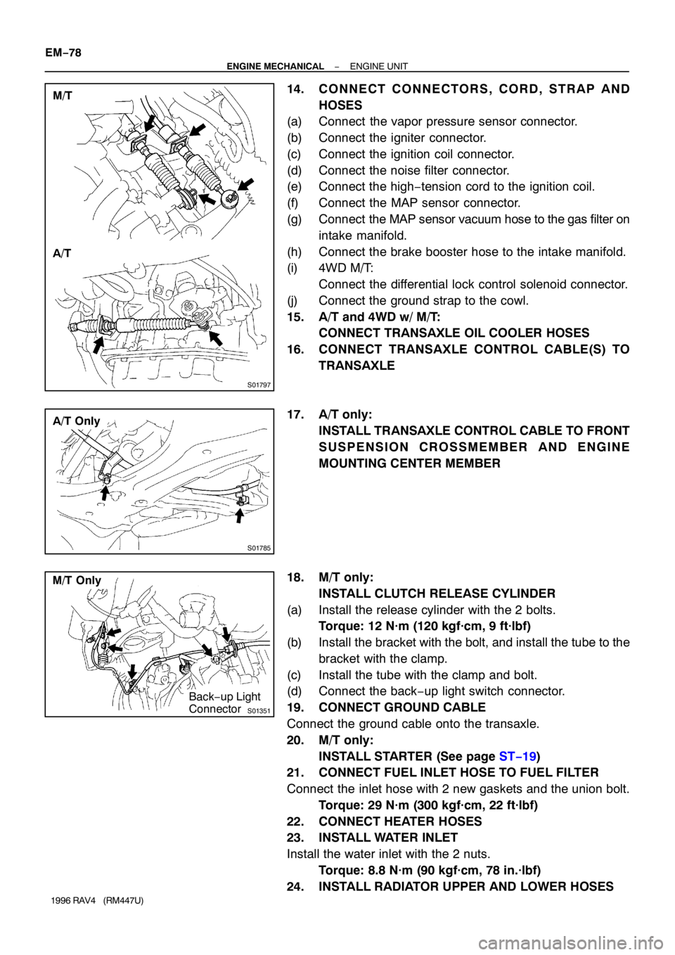
14. CONNECT CONNECTORS, CORD, STRAP AND
HOSES
(a) Connect the vapor pressure sensor connector.
(b) Connect the igniter connector.
(c) Connect the ignition coil connector.
(d) Connect the noise filter connector.
(e) Connect the high−tension cord to the ignition coil.
(f) Connect the MAP sensor connector.
(g) Connect the MAP sensor vacuum hose to the gas filter on
intake manifold.
(h) Connect the brake booster hose to the intake manifold.
(i) 4WD M/T:
Connect the differential lock control solenoid connector.
(j) Connect the ground strap to the cowl.
15. A/T and 4WD w/ M/T:
CONNECT TRANSAXLE OIL COOLER HOSES
16. CONNECT TRANSAXLE CONTROL CABLE(S) TO
TRANSAXLE
17. A/T only:
INSTALL TRANSAXLE CONTROL CABLE TO FRONT
SUSPENSION CROSSMEMBER AND ENGINE
MOUNTING CENTER MEMBER
18. M/T only:
INSTALL CLUTCH RELEASE CYLINDER
(a) Install the release cylinder with the 2 bolts.
Torque: 12 N·m (120 kgf·cm, 9 ft·lbf)
(b) Install the bracket with the bolt, and install the tube to the
bracket with the clamp.
(c) Install the tube with the clamp and bolt.
(d) Connect the back−up light switch connector.
19. CONNECT GROUND CABLE
Connect the ground cable onto the transaxle.
20. M/T only:
INSTALL STARTER (See page ST−19)
21. CONNECT FUEL INLET HOSE TO FUEL FILTER
Connect the inlet hose with 2 new gaskets and the union bolt.
Torque: 29 N·m (300 kgf·cm, 22 ft·lbf)
22. CONNECT HEATER HOSES
23. INSTALL WATER INLET
Install the water inlet with the 2 nuts.
Torque: 8.8 N·m (90 kgf·cm, 78 in.·lbf)
24. INSTALL RADIATOR UPPER AND LOWER HOSES
Page 785 of 1354
15
ABBREVIATIONS D
ABBREVIATIONS
The following abbreviations are used in this manual.
ABS = Anti-Lock Brake System
A/C = Air Conditioning
A/T = Automatic Transaxle
COMB. = Combination
DIFF. = Differential
ECU = Electronic Control Unit
EGR = Exhaust Gas Recirculation
EVAP = Evaporative Emission
J/B = Junction Block
LH = Left-Hand
M/T = Manual Transaxle
O/D = Overdrive
R/B = Relay Block
RH = Right-Hand
SFI = Sequential Multiport Fuel Injection
SRS = Supplemental Restraint System
SW = Switch
TEMP. = Temperature
VSV = Vacuum Switching Valve
w/ = With
w/o = Without
2WD = Two Wheel Drive
4WD = Four Wheel Drive
* The titles given inside the components are the names of the terminals (terminal codes) and are not
treated as being abbreviations.
Page 1003 of 1354
MX05R−02
Q09030
Solenoid Hose No.1
Transfer Vacuum Actuator
Bracket
Transfer Vacuum Actuator Assembly
Right Transfer Stiffener Plate
Center Transfer Stiffener Plate
Differential Lock Indicator Switch Connector
Back−Up Light
Switch Connector
Vehicle Speed
Sensor Connector
Transaxle Case Protector
Starter Stiffener Plate
N·m (kgf·cm, ft·lbf): Specified torque
25 (250, 18)
37 (380, 27)
9.0 (95, 78 in.·lbf)
37 (380, 27)
37 (380, 27)
37 (380, 27)
37 (380, 27)
37 (380, 27)
37 (380, 27)
37 (380, 27)
37 (380, 27)
37 (380, 27)
46 (470, 34)
29 (300, 22)
25 (250, 18)
64 (650, 47)
39 (400, 29)
64 (650, 47)
35 (360, 26)
29 (300, 22)
Solenoid Hose No.0
Solenoid Hose No.2
Solenoid Hose No.0 MX−8
− MANUAL TRANSAXLEMANUAL TRANSAXLE UNIT (4WD)
1996 RAV4 (RM447U)
MANUAL TRANSAXLE UNIT (4WD)
COMPONENTS