Page 611 of 1354

DI7HO−01
I10026CRUISE Control ECU DI−334
− DIAGNOSTICSCRUISE CONTROL SYSTEM
1996 RAV4 (RM447U)
TERMINALS OF ECU
SymbolsTerminalsConditionStandard Value
D ↔ GND2 − 13
M/T: Depress clutch pedal.
A/T: Shift to except D position.Below 1 V
M/T: Release clutch pedal.
A/T: Shift to D position.10 − 16 V
Pi ↔ GND7 − 13
IG ON. Main switch ON.
Main indicator light ON.Below 1.2 V
IG ON. Main switch OFF.
Main indicator light OFF.10 − 16 V
Tc ↔ GND8 − 13Ignition switch ON.10 − 16 V
O/D ↔ GND9 − 13
Except during cruise control driving.10 − 16 V
O/D Switch ON.
During cruise control driving .
(Driving on flat road).
10 − 16 V
O/D Switch OFF.
During cruise control driving .
(3rd driving).
Below 1 V
L ↔ GND10 − 13During cruise control driving.9 − 15 V
Except during cruise control driving.Below 1 V
MC ↔ GND11 − 13
During cruise control driving .
COAST switch hold ON.9 − 16 V
During cruise control driving .
ACCEL switch hold ON.Below 1 V
MO ↔ GND12 − 13
During cruise control driving.
ACCEL switch hold ON.9 − 15 V
During cruise control driving.
COAST switch hold ON.Below 1 V
GND ↔ Body Ground13 −
Body GroundAlways.Below 1 V
B ↔ GND14 − 13Ignition switch ON.10 − 16 V
BATT ↔ GND15 − 13Always.10 − 16 V
STP− ↔ GND16 − 13Depress brake pedal.10 − 16 V
Release brake pedal.Below 1 V
Page 613 of 1354

DI42M−01
DI−336
− DIAGNOSTICSCRUISE CONTROL SYSTEM
1996 RAV4 (RM447U)
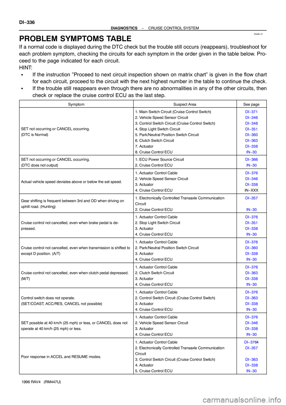
PROBLEM SYMPTOMS TABLE
If a normal code is displayed during the DTC check but the trouble still occurs (reappears), troubleshoot for
each problem symptom, checking the circuits for each symptom in the order given in the table below. Pro-
ceed to the page indicated for each circuit.
HINT:
�If the instruction ”Proceed to next circuit inspection shown on matrix chart” is given in the flow chart
for each circuit, proceed to the circuit with the next highest number in the table to continue the check.
�If the trouble still reappears even through there are no abnormalities in any of the other circuits, then
check or replace the cruise control ECU as the last step.
SymptomSuspect AreaSee page
SET not occurring or CANCEL occurring.
(DTC is Normal)
1. Main Switch Circuit (Cruise Control Switch)
2. Vehicle Speed Sensor Circuit
3. Control Switch Circuit (Cruise Control Switch)
4. Stop Light Switch Circuit
5. Park/Neutral Position Switch Circuit
6. Clutch Switch Circuit
7. Actuator
8. Cruise Control ECUDI−371
DI−346
DI−348
DI−351
DI−360
DI−363
DI−338
IN−30
SET not occurring or CANCEL occurring.
(DTC does not output)1. ECU Power Source Circuit
2. Cruise Control ECUDI−366
IN−30
Actual vehicle speed deviates above or below the set speed.
1. Actuator Control Cable
2. Vehicle Speed Sensor Circuit
3. Actuator
4. Cruise Control ECUDI−376
DI−346
DI−338
IN−XXX
Gear shifting is frequent between 3rd and OD when driving on
uphill road. (Hunting)1. Electronically Controlled Transaxle Communication
Circuit
2. Cruise Control ECUDI−357
IN−30
Cruise control not cancelled, even when brake pedal is de-
pressed.
1. Actuator Control Cable
2. Stop Light Switch Circuit
3. Actuator
4. Cruise Control ECUDI−376
DI−351
DI−338
IN−30
Cruise control not cancelled, even when transmission is shifted to
except D position. (A/T)
1. Actuator Control Cable
2. Park/Neutral Position Switch Circuit
3. Actuator
4. Cruise Control ECUDI−376
DI−360
DI−338
IN−30
Cruise control not cancelled, even when clutch pedal depressed.
(M/T)
1. Actuator Control Cable
2. Clutch Switch Circuit
3. Actuator
4. Cruise Control ECUDI−376
DI−363
DI−338
IN−30
Control switch does not operate.
(SET/COAST, ACC/RES, CANCEL not possible)
1. Actuator Control Cable
2. Control Switch Circuit (Cruise Control Switch)
3. Actuator
4. Cruise Control ECUDI−376
DI−363
DI−338
IN−30
SET possible at 40 km/h (25 mph) or less, or CANCEL does not
operate at 40 km/h (25 mph) or less.
1. Actuator Control Cable
2. Vehicle Speed Sensor Circuit
3. Actuator
4. Cruise Control ECUDI−376
DI−346
DI−338
IN−30
Poor response in ACCEL and RESUME modes.
1. Actuator Control Cable
2. Electronically Controlled Transaxle Communication
Circuit
3. Control Switch Circuit (Cruise Control Switch)
4. Actuator
5. Cruise Control ECUDI−3764
DI−357
DI−363
DI−338
IN−30
Page 617 of 1354

N17894
Cruise Control
Actuator
457
16 IB2 STOP FuseStop Light SwitchCruise Control ECU
STP−
L
L− 26 1016 1
3 4 2
G−W
G−B
L−B L−B R−Y
R−Y R−W
GNDL
IB2 DI−340
− DIAGNOSTICSCRUISE CONTROL SYSTEM
1996 RAV4 (RM447U)
DTC 12 Actuator Magnetic Clutch Circuit
CIRCUIT DESCRIPTION
This circuit turns on the magnetic clutch inside the actuator during cruise control operation according to the
signal from the ECU. If a malfunction occurs in the actuator or vehicle speed sensor, etc. during cruise con-
trol, the rotor shaft between the motor and control plate is released.
When the brake pedal is depressed, the stop light switch turns on, supplying electrical power to the stop light.
Power supply to the magnetic clutch is mechanically cut and the magnetic clutch is turned OFF.
When driving downhill, if the vehicle speed exceeds the set speed by 15 km/h (9 mph), the ECU turns the
magnetic clutch OFF. If the vehicle speed later drops to within 10 km/h (6 mph) above the set speed, then
cruise control at the set speed is resumed.
DTC No.Detection ItemTrouble Area
12�Short in magnetic clutch circuit
�Open (0.8 sec.) in magnetic clutch circuit
�Cruise contorl actuator magnetic clutch
�Harness or connector between ECU and magnetic clutch,
magnetic clutch and body ground
�ECU
�STOP Fuse
WIRING DIAGRAM
DI42O−02
Page 619 of 1354
BE1444BE6234I09113
2
1
43
Switch Pin
DI−342
− DIAGNOSTICSCRUISE CONTROL SYSTEM
1996 RAV4 (RM447U)
3 Check stop light switch.
PREPARATION:
Disconnect stop light switch connector.
CHECK:
Check continuity between terminals.
OK:
Switch positionTerminal No. to continuity
Switch pin free
(Brake pedal depressed)1 − 2
Switch pin pushed in
(Brake pedal released)3 − 4
NG Replace stop light switch.
OK
4 Check for open and short in harness and connectors between ECU and stop
light switch, stop light switch and magnetic clutch, magnetic clutch and body
ground (See page IN−30).
NG Repair or replace harness or connector.
OK
Proceed to next circuit inspection shown on matrix chart (See page DI−336).
However, when DTC 12 is displayed, check harness and connector for loose connection.
If connection is normal, check and replace ECU.
Page 628 of 1354
N17898
Ignition
SwitchSTOP FuseStop Light
SwitchCruise Control
ECU
STP−
L
L−
GNDL5
47 211
1F1I
IB2
IB2 16
L−BG−B10
2616 1
3 42
R−W R−WJ/B No.1
R−Y
L−BG−W
R−Y
10 A
Cruise Control
Actuator
− DIAGNOSTICSCRUISE CONTROL SYSTEM
DI−351
1996 RAV4 (RM447U)
Stop Light Switch Circuit
CIRCUIT DESCRIPTION
When the brake is on, battery positive voltage normally applies through the stop fuse and stop light switch
to terminal STP− of the ECU, and the ECU turns the cruise control off.
A fail−safe function is provided so that cancel functions normally, even if there is a malfunction in the stop
light signal circuit.
If the harness connected to terminal STP− has an open, terminal STP− will have battery positive voltage and
the cruise control will be turned off, also SET not occurring.
Also, when the brake is on, the magnetic clutch is cut electrically by the stop light switch, turning the cruise
control off. (See page DI−338 for operation of the magnetic clutch)
WIRING DIAGRAM
DI42S−02
Page 629 of 1354
ON
OFFBrake pedal is depressed
DI−352
− DIAGNOSTICSCRUISE CONTROL SYSTEM
1996 RAV4 (RM447U)
INSPECTION PROCEDURE
1 Check operation of stop light.
CHECK:
Check that stop light comes on when brake pedal is depressed, and turns off when brake pedal is released.
NG Check stop light circuit.
OK
2 Input signal check.
CHECK:
(a) See input signal check on page DI−328.
(b) Check the indicator light when the brake pedal is de-
pressed.
OK:
The indicator light goes off when the brake pedal is
depressed.
OK Proceed to next circuit inspection shown on
matrix chart (See page DI−336).
NG
Page 630 of 1354
BE3840N16656I09118
ON
STP−
(−)(+)
− DIAGNOSTICSCRUISE CONTROL SYSTEM
DI−353
1996 RAV4 (RM447U)
3 Check voltage between terminal, STP− of ECU connector and body ground.
PREPARATION:
Remove ECU with connectors still connected.
CHECK:
(a) Turn ignition switch ON.
(b) Measure voltage between terminal STP−of ECU connec-
tor and body ground, when the brake pedal is depressed
and released.
OK:
Pedal positionVoltage
Depressed10 − 16 V
ReleasedBelow 1 V
OK Proceed to next circuit inspection shown on
matrix chart (See page DI−336).
NG
4 Check for open in harness and connectors between terminal STP− of ECU and
stop light switch (See page IN−30).
NG Repair or replace harness or connector.
OK
Check and replace ECU.
Page 744 of 1354

S01797
M/T
A/T
S01785
A/T Only
S01351
M/T Only
Back−up Light
Connector EM−78
− ENGINE MECHANICALENGINE UNIT
1996 RAV4 (RM447U)
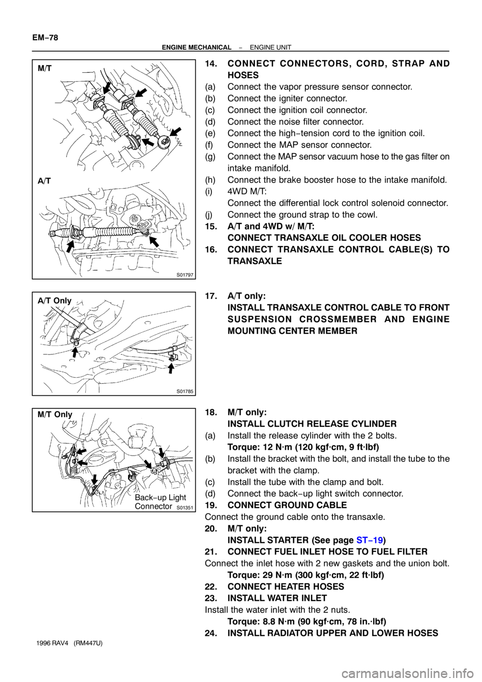
14. CONNECT CONNECTORS, CORD, STRAP AND
HOSES
(a) Connect the vapor pressure sensor connector.
(b) Connect the igniter connector.
(c) Connect the ignition coil connector.
(d) Connect the noise filter connector.
(e) Connect the high−tension cord to the ignition coil.
(f) Connect the MAP sensor connector.
(g) Connect the MAP sensor vacuum hose to the gas filter on
intake manifold.
(h) Connect the brake booster hose to the intake manifold.
(i) 4WD M/T:
Connect the differential lock control solenoid connector.
(j) Connect the ground strap to the cowl.
15. A/T and 4WD w/ M/T:
CONNECT TRANSAXLE OIL COOLER HOSES
16. CONNECT TRANSAXLE CONTROL CABLE(S) TO
TRANSAXLE
17. A/T only:
INSTALL TRANSAXLE CONTROL CABLE TO FRONT
SUSPENSION CROSSMEMBER AND ENGINE
MOUNTING CENTER MEMBER
18. M/T only:
INSTALL CLUTCH RELEASE CYLINDER
(a) Install the release cylinder with the 2 bolts.
Torque: 12 N·m (120 kgf·cm, 9 ft·lbf)
(b) Install the bracket with the bolt, and install the tube to the
bracket with the clamp.
(c) Install the tube with the clamp and bolt.
(d) Connect the back−up light switch connector.
19. CONNECT GROUND CABLE
Connect the ground cable onto the transaxle.
20. M/T only:
INSTALL STARTER (See page ST−19)
21. CONNECT FUEL INLET HOSE TO FUEL FILTER
Connect the inlet hose with 2 new gaskets and the union bolt.
Torque: 29 N·m (300 kgf·cm, 22 ft·lbf)
22. CONNECT HEATER HOSES
23. INSTALL WATER INLET
Install the water inlet with the 2 nuts.
Torque: 8.8 N·m (90 kgf·cm, 78 in.·lbf)
24. INSTALL RADIATOR UPPER AND LOWER HOSES