Page 1212 of 1354
SA0UV−01
R10753
SA−98
− SUSPENSION AND AXLEREAR SUSPENSION ARM AND COIL SPRING
1996 RAV4 (RM447U)
INSPECTION
INSPECT BALL JOINT FOR ROTATION CONDITION
(a) As shown in the illustration, flip the ball joint stud back and
forth 5 times, before installing the nut.
(b) Using a torque wrench, turn the nut continuously one turn
each 2 − 4 seconds and take the torque reading on the 5th
turn.
Turning Torque:
Upper suspension arm:
0.5 − 3.5 N·m (5 − 35 kgf·cm, 7 − 30 in.·lbf)
Lower suspension arm:
0.5 − 3.5 N·m (5 − 35 kgf·cm, 7 − 30 in.·lbf)
Page 1213 of 1354

SA0UW−01
W01228
R11091
SST
R11092
5°
5°SST
Horizontal Line
Press Line
Position Mark
− SUSPENSION AND AXLEREAR SUSPENSION ARM AND COIL SPRING
SA−99
1996 RAV4 (RM447U)
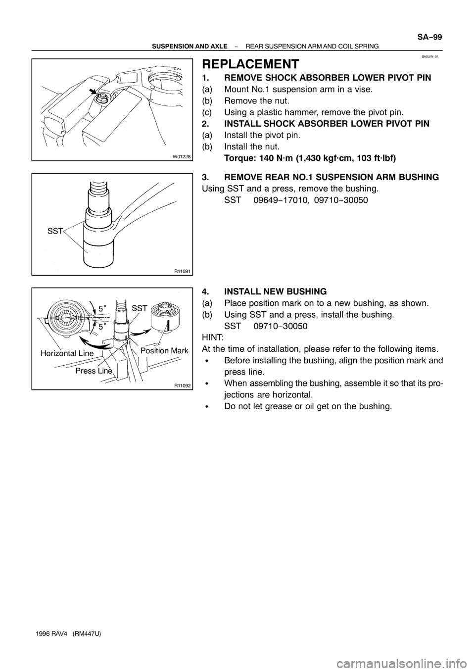
REPLACEMENT
1. REMOVE SHOCK ABSORBER LOWER PIVOT PIN
(a) Mount No.1 suspension arm in a vise.
(b) Remove the nut.
(c) Using a plastic hammer, remove the pivot pin.
2. INSTALL SHOCK ABSORBER LOWER PIVOT PIN
(a) Install the pivot pin.
(b) Install the nut.
Torque: 140 N·m (1,430 kgf·cm, 103 ft·lbf)
3. REMOVE REAR NO.1 SUSPENSION ARM BUSHING
Using SST and a press, remove the bushing.
SST 09649−17010, 09710−30050
4. INSTALL NEW BUSHING
(a) Place position mark on to a new bushing, as shown.
(b) Using SST and a press, install the bushing.
SST 09710−30050
HINT:
At the time of installation, please refer to the following items.
�Before installing the bushing, align the position mark and
press line.
�When assembling the bushing, assemble it so that its pro-
jections are horizontal.
�Do not let grease or oil get on the bushing.
Page 1214 of 1354
SA0UX−04
SA−100
− SUSPENSION AND AXLEREAR SUSPENSION ARM AND COIL SPRING
1996 RAV4 (RM447U)
INSTALLATION
Installation is in the reverse order of removal (See page SA−96).
AFTER INSTALLATION, CHECK ABS SPEED SENSOR SIGNAL (See page DI−257) AND REAR WHEEL
ALIGNMENT (See page SA−7)
Page 1268 of 1354
SF0RG−02
S01838
2WD
SST
P01630
Ohmmeter
− SFIKNOCK SENSOR
SF−57
1996 RAV4 (RM447U)
INSPECTION
1. 4WD:
REMOVE ENGINE AND TRANSAXLE ASSEMBLY (See
page EM−68)
2. REMOVE KNOCK SENSOR
(a) Disconnect the knock sensor connector.
(b) Using SST, remove the knock sensor.
SST 09816−30010
Torque: 44 N·m (450 kgf·cm, 33 ft·lbf)
3. INSPECT KNOCK SENSOR
Using an ohmmeter, check that there is no continuity between
the terminal and body.
If there is continuity, replace the sensor.
4. REINSTALL KNOCK SENSOR
Installation is in the reverse order of removal.
5. 4WD:
REINSTALL ENGINE AND TRANSAXLE ASSEMBLY
(See page EM−74)