Page 1147 of 1354
SA0TL−03
R10850
R10823
− SUSPENSION AND AXLEFRONT SHOCK ABSORBER
SA−33
1996 RAV4 (RM447U)
REMOVAL
1. REMOVE FRONT WHEEL
Torque: 103 N·m (1,050 kgf·cm, 76 ft·lbf)
2. DISCONNECT FLEXIBLE HOSE AND ABS SPEED
SENSOR WIRE HARNESS (w/ ABS) FROM SHOCK
ABSORBER
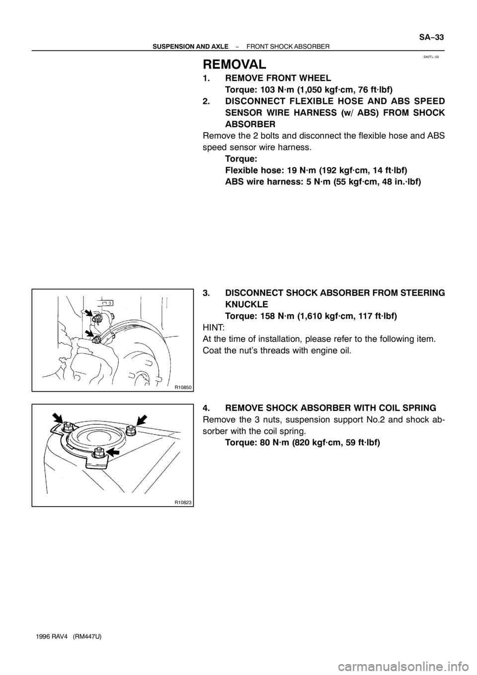
Remove the 2 bolts and disconnect the flexible hose and ABS
speed sensor wire harness.
Torque:
Flexible hose: 19 N·m (192 kgf·cm, 14 ft·lbf)
ABS wire harness: 5 N·m (55 kgf·cm, 48 in.·lbf)
3. DISCONNECT SHOCK ABSORBER FROM STEERING
KNUCKLE
Torque: 158 N·m (1,610 kgf·cm, 117 ft·lbf)
HINT:
At the time of installation, please refer to the following item.
Coat the nut’s threads with engine oil.
4. REMOVE SHOCK ABSORBER WITH COIL SPRING
Remove the 3 nuts, suspension support No.2 and shock ab-
sorber with the coil spring.
Torque: 80 N·m (820 kgf·cm, 59 ft·lbf)
Page 1154 of 1354
SA0TS−03
R10828
A
A B
R10829
W01708
SA−40
− SUSPENSION AND AXLEFRONT LOWER SUSPENSION ARM
1996 RAV4 (RM447U)
REMOVAL
1. REMOVE FRONT WHEEL
Torque: 103 N·m (1,050 kgf·cm, 76 ft·lbf)
2. A/T LH:
REMOVE LH ENGINE UNDER COVER
3. EXCEPT A/T LH:
DISCONNECT STABILIZER BAR LINK FROM LOWER
SUSPENSION ARM (See page SA−48)
4. A/T LH:
REMOVE STABILIZER BAR (See page SA−48)
5. DISCONNECT LOWER SUSPENSION ARM FROM
LOWER BALL JOINT
Remove the bolt and 2 nuts.
Torque: 127 N·m (1,300 kgf·cm, 94 ft·lbf)
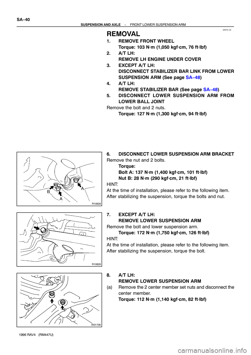
6. DISCONNECT LOWER SUSPENSION ARM BRACKET
Remove the nut and 2 bolts.
Torque:
Bolt A: 137 N·m (1,400 kgf·cm, 101 ft·lbf)
Nut B: 28 N·m (290 kgf·cm, 21 ft·lbf)
HINT:
At the time of installation, please refer to the following item.
After stabilizing the suspension, torque the bolts and nut.
7. EXCEPT A/T LH:
REMOVE LOWER SUSPENSION ARM
Remove the bolt and lower suspension arm.
Torque: 172 N·m (1,750 kgf·cm, 126 ft·lbf)
HINT:
At the time of installation, please refer to the following item.
After stabilizing the suspension, torque the bolt.
8. A/T LH:
REMOVE LOWER SUSPENSION ARM
(a) Remove the 2 center member set nuts and disconnect the
center member.
Torque: 112 N·m (1,140 kgf·cm, 82 ft·lbf)
Page 1162 of 1354
SA0TZ−02
R10835
R10836
Rear
Paint Line SA−48
− SUSPENSION AND AXLEFRONT STABILIZER BAR
1996 RAV4 (RM447U)
REMOVAL
1. REMOVE FRONT WHEELS
Torque: 103 N·m (1,050 kgf·cm 76 ft·lbf)
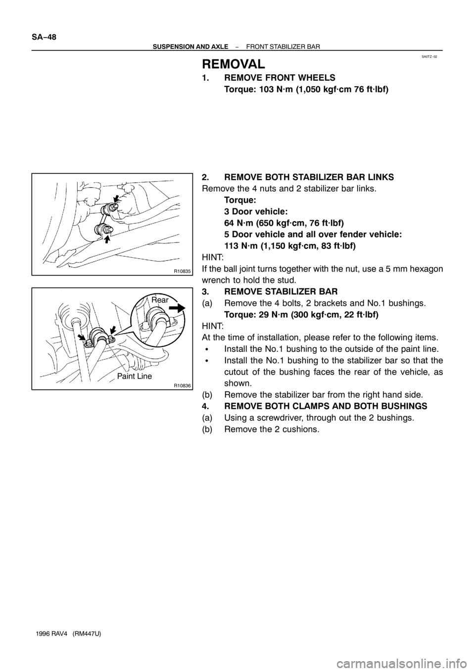
2. REMOVE BOTH STABILIZER BAR LINKS
Remove the 4 nuts and 2 stabilizer bar links.
Torque:
3 Door vehicle:
64 N·m (650 kgf·cm, 76 ft·lbf)
5 Door vehicle and all over fender vehicle:
113 N·m (1,150 kgf·cm, 83 ft·lbf)
HINT:
If the ball joint turns together with the nut, use a 5 mm hexagon
wrench to hold the stud.
3. REMOVE STABILIZER BAR
(a) Remove the 4 bolts, 2 brackets and No.1 bushings.
Torque: 29 N·m (300 kgf·cm, 22 ft·lbf)
HINT:
At the time of installation, please refer to the following items.
�Install the No.1 bushing to the outside of the paint line.
�Install the No.1 bushing to the stabilizer bar so that the
cutout of the bushing faces the rear of the vehicle, as
shown.
(b) Remove the stabilizer bar from the right hand side.
4. REMOVE BOTH CLAMPS AND BOTH BUSHINGS
(a) Using a screwdriver, through out the 2 bushings.
(b) Remove the 2 cushions.
Page 1170 of 1354
SA0U6−02
R10700
SST
R10750
SA−56
− SUSPENSION AND AXLEREAR AXLE HUB (4WD)
1996 RAV4 (RM447U)
REMOVAL
1. REMOVE REAR WHEEL
Torque: 103 N·m (1,050 kgf·cm, 76 ft·lbf)
2. REMOVE BRAKE DRUM
3. CHECK BEARING BACKLASH AND AXLE HUB DEVI-
ATION (See page SA−52)
4. REMOVE BOLT AND ABS SPEED SENSOR
Torque: 8 N·m (80 kgf·cm, 69 in.·lbf)
5. REMOVE REAR DRIVE SHAFT (See page SA−62)
6. DISASSEMBLE REAR BRAKE (See page BR−30)
7. DISCONNECT BRAKE LINE
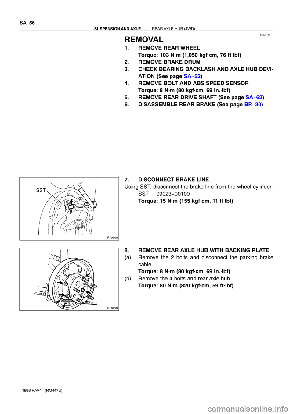
Using SST, disconnect the brake line from the wheel cylinder.
SST 09023−00100
Torque: 15 N·m (155 kgf·cm, 11 ft·lbf)
8. REMOVE REAR AXLE HUB WITH BACKING PLATE
(a) Remove the 2 bolts and disconnect the parking brake
cable.
Torque: 8 N·m (80 kgf·cm, 69 in.·lbf)
(b) Remove the 4 bolts and rear axle hub.
Torque: 80 N·m (820 kgf·cm, 59 ft·lbf)
Page 1210 of 1354
SA0UU−03
R10779
R10764
SST
R10765
SST SA−96
− SUSPENSION AND AXLEREAR SUSPENSION ARM AND COIL SPRING
1996 RAV4 (RM447U)
REMOVAL
1. REMOVE REAR WHEEL
Torque: 103 N·m (1,050 kgf·cm, 76 ft·lbf)
2. 2WD:
REMOVE AXLE SHAFT (See page SA−52)
3. 4WD:
REMOVE REAR DRIVE SHAFT (See page SA−62)
4. REMOVE BRAKE DRUM
5. REMOVE 2 BRAKE LINE CLAMP BOLTS
Torque:
Bracket: 18 N·m (185 kgf·cm, 13 ft·lbf)
Clamp: 13 N·m (130 kgf·cm, 9 ft·lbf)
6. REMOVE PARKING BRAKE CABLE CLAMP BOLT
Torque: 19 N·m (195 kgf·cm, 14 ft·lbf)
7. w/ ABS:
REMOVE ABS SPEED SENSOR AND WIRE HARNESS
Torque:
ABS speed sensor: 8 N·m (80 kgf·cm, 69 in.·lbf)
Wire harness: 13 N·m (130 kgf·cm, 9 ft·lbf)
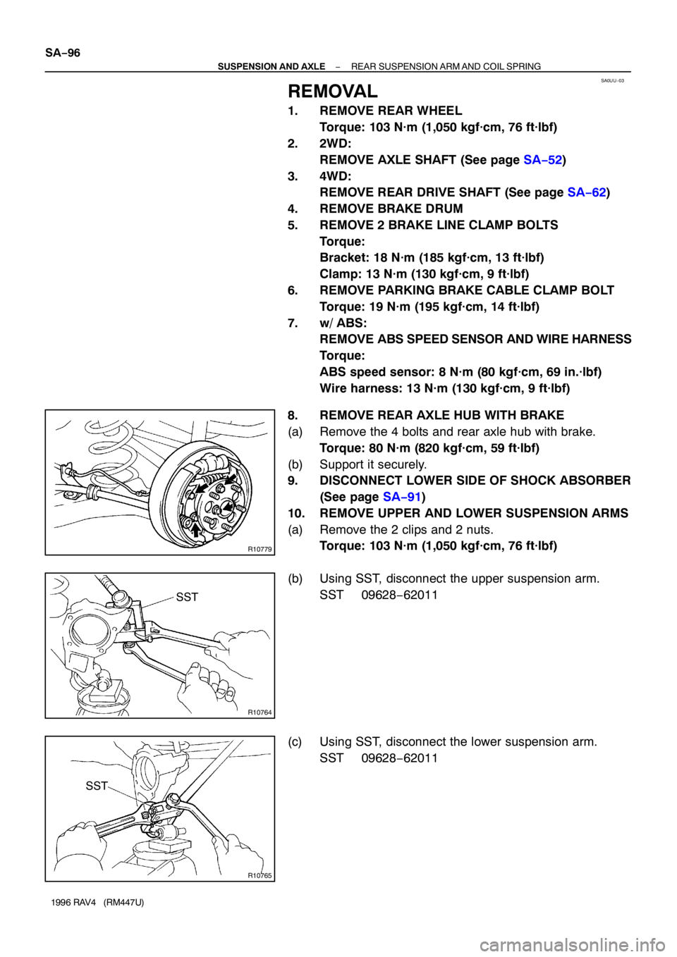
8. REMOVE REAR AXLE HUB WITH BRAKE
(a) Remove the 4 bolts and rear axle hub with brake.
Torque: 80 N·m (820 kgf·cm, 59 ft·lbf)
(b) Support it securely.
9. DISCONNECT LOWER SIDE OF SHOCK ABSORBER
(See page SA−91)
10. REMOVE UPPER AND LOWER SUSPENSION ARMS
(a) Remove the 2 clips and 2 nuts.
Torque: 103 N·m (1,050 kgf·cm, 76 ft·lbf)
(b) Using SST, disconnect the upper suspension arm.
SST 09628−62011
(c) Using SST, disconnect the lower suspension arm.
SST 09628−62011
Page 1294 of 1354
W02017
Non−tilt Steering Column :
Tilt−Steering Column :
MatchmarksBA
SR−20
− STEERINGNON−TILT STEERING COLUMN
1996 RAV4 (RM447U)
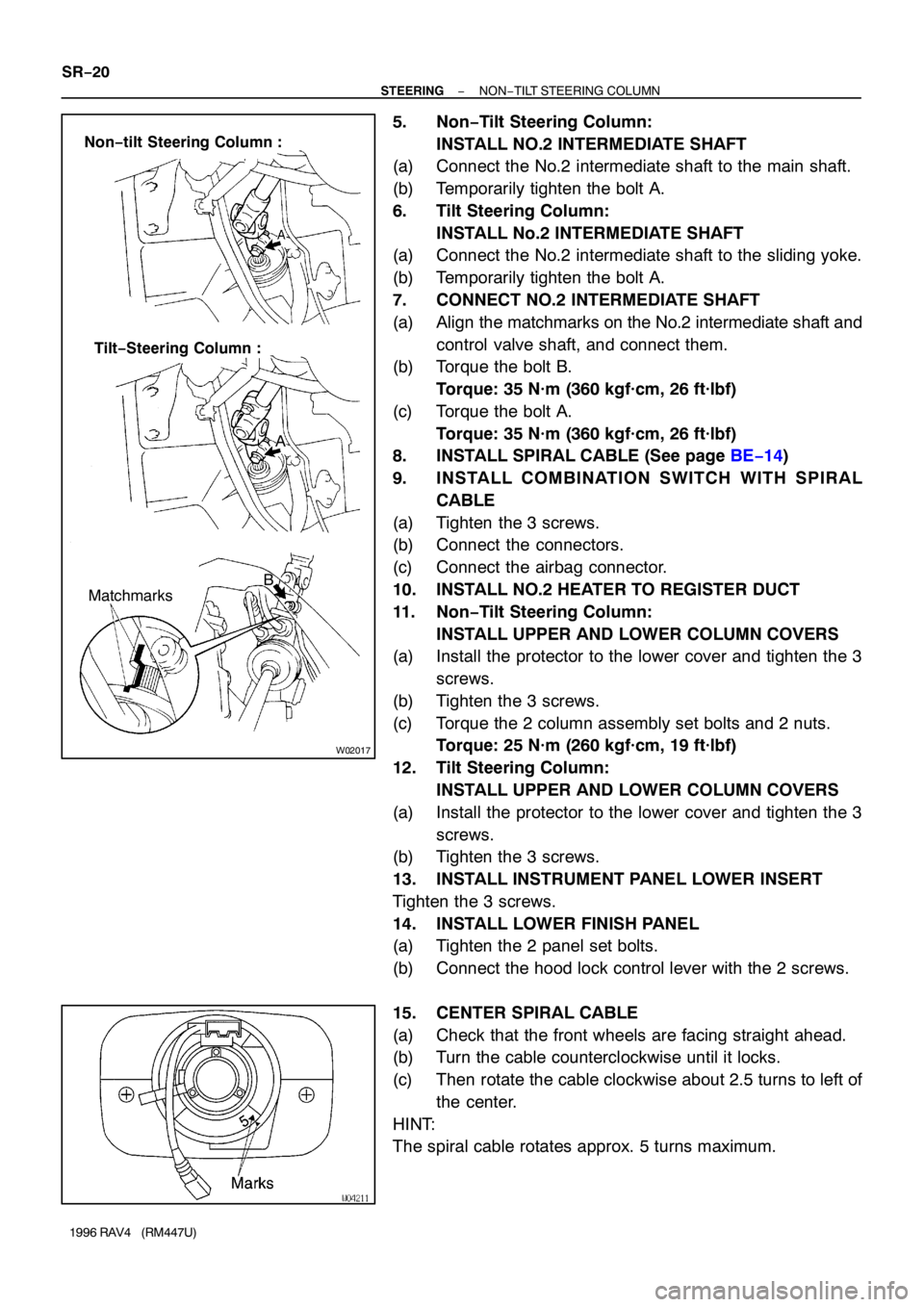
5. Non−Tilt Steering Column:
INSTALL NO.2 INTERMEDIATE SHAFT
(a) Connect the No.2 intermediate shaft to the main shaft.
(b) Temporarily tighten the bolt A.
6. Tilt Steering Column:
INSTALL No.2 INTERMEDIATE SHAFT
(a) Connect the No.2 intermediate shaft to the sliding yoke.
(b) Temporarily tighten the bolt A.
7. CONNECT NO.2 INTERMEDIATE SHAFT
(a) Align the matchmarks on the No.2 intermediate shaft and
control valve shaft, and connect them.
(b) Torque the bolt B.
Torque: 35 N·m (360 kgf·cm, 26 ft·lbf)
(c) Torque the bolt A.
Torque: 35 N·m (360 kgf·cm, 26 ft·lbf)
8. INSTALL SPIRAL CABLE (See page BE−14)
9. INSTALL COMBINATION SWITCH WITH SPIRAL
CABLE
(a) Tighten the 3 screws.
(b) Connect the connectors.
(c) Connect the airbag connector.
10. INSTALL NO.2 HEATER TO REGISTER DUCT
11. Non−Tilt Steering Column:
INSTALL UPPER AND LOWER COLUMN COVERS
(a) Install the protector to the lower cover and tighten the 3
screws.
(b) Tighten the 3 screws.
(c) Torque the 2 column assembly set bolts and 2 nuts.
Torque: 25 N·m (260 kgf·cm, 19 ft·lbf)
12. Tilt Steering Column:
INSTALL UPPER AND LOWER COLUMN COVERS
(a) Install the protector to the lower cover and tighten the 3
screws.
(b) Tighten the 3 screws.
13. INSTALL INSTRUMENT PANEL LOWER INSERT
Tighten the 3 screws.
14. INSTALL LOWER FINISH PANEL
(a) Tighten the 2 panel set bolts.
(b) Connect the hood lock control lever with the 2 screws.
15. CENTER SPIRAL CABLE
(a) Check that the front wheels are facing straight ahead.
(b) Turn the cable counterclockwise until it locks.
(c) Then rotate the cable clockwise about 2.5 turns to left of
the center.
HINT:
The spiral cable rotates approx. 5 turns maximum.
Page 1321 of 1354
SR0G2−03
R10984
SST
− STEERINGPOWER STEERING GEAR
SR−47
1996 RAV4 (RM447U)
REMOVAL
NOTICE:
Remove the steering wheel assembly before the steering
gear removal, because there is possibility of breaking of
the spiral cable.
1. PLACE FRONT WHEELS FACING STRAIGHT AHEAD
2. REMOVE STEERING WHEEL PAD (See page SR−12)
3. REMOVE STEERING WHEEL (See page SR−12)
4. REMOVE RH AND LH ENGINE UNDER COVERS
Remove the 13 bolts.
5. DISCONNECT RH AND LH TIE ROD ENDS
(See page SA−10)
6. REMOVE FRONT EXHAUST PIPE
Remove the 2 bolts, 3 nuts and 2 gaskets.
7. REMOVE STABILIZER BAR WITH LINK
(See page SA−48)
8. DISCONNECT NO.2 INTERMEDIATE SHAFT
(See page SR−12)
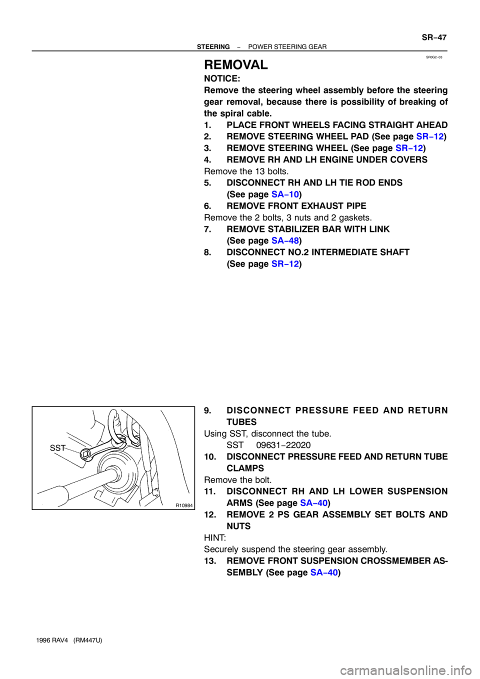
9. DISCONNECT PRESSURE FEED AND RETURN
TUBES
Using SST, disconnect the tube.
SST 09631−22020
10. DISCONNECT PRESSURE FEED AND RETURN TUBE
CLAMPS
Remove the bolt.
11. DISCONNECT RH AND LH LOWER SUSPENSION
ARMS (See page SA−40)
12. REMOVE 2 PS GEAR ASSEMBLY SET BOLTS AND
NUTS
HINT:
Securely suspend the steering gear assembly.
13. REMOVE FRONT SUSPENSION CROSSMEMBER AS-
SEMBLY (See page SA−40)
Page 1334 of 1354
SR0G6−02
W01119
SST
Fulcrum Length SR−60
− STEERINGPOWER STEERING GEAR
1996 RAV4 (RM447U)
INSTALLATION
1. CONNECT PRESSURE FEED AND RETURN TUBE
CLAMPS
Torque the bolt.
Torque: 13 N·m (130 kgf·cm, 9 ft·lbf)
2. INSTALL FRONT SUSPENSION CROSSMEMBER AS-
SEMBLY (See page SA−42)
3. TORQUE 2 PS GEAR ASSEMBLY SET BOLTS AND
NUTS
Torque: 113 N·m (1,150 kgf·cm, 83 ft·lbf)
4. CONNECT RH AND LH LOWER SUSPENSION ARMS
(See page SA−42)
5. INSTALL STABILIZER BAR WITH LINK
(See page SA−50)
6. INSTALL FRONT EXHAUST PIPE
(a) Torque the 2 bolts with a new gasket.
Torque: 48 N·m (490 kgf·cm, 35 ft·lbf)
(b) Torque 3 new nuts with a new gasket.
Torque: 62 N·m (630 kgf·cm, 46 ft·lbf)
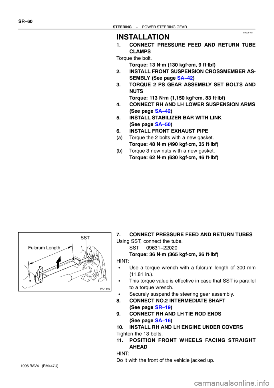
7. CONNECT PRESSURE FEED AND RETURN TUBES
Using SST, connect the tube.
SST 09631−22020
Torque: 36 N·m (365 kgf·cm, 26 ft·lbf)
HINT:
�Use a torque wrench with a fulcrum length of 300 mm
(11.81 in.).
�This torque value is effective in case that SST is parallel
to a torque wrench.
�Securely suspend the steering gear assembly.
8. CONNECT NO.2 INTERMEDIATE SHAFT
(See page SR−19)
9. CONNECT RH AND LH TIE ROD ENDS
(See page SA−16)
10. INSTALL RH AND LH ENGINE UNDER COVERS
Tighten the 13 bolts.
11. POSITION FRONT WHEELS FACING STRAIGHT
AHEAD
HINT:
Do it with the front of the vehicle jacked up.
Page:
< prev 1-8 9-16 17-24