Page 737 of 1354
S01434
S01364
S01362
S01363
S01283
B
SST
A
− ENGINE MECHANICALENGINE UNIT
EM−71
1996 RAV4 (RM447U)
29. REMOVE FRONT SUSPENSION CROSSMEMBER
(a) Remove the 2 bolts and 2 nuts holding the PS gear as-
sembly to the front suspension crossmember.
(b) Remove the 2 nuts, and disconnect the engine mounting
center member.
(c) Disconnect the TWC w/ pipe from the ring.
(d) Support the front suspension crossmember with a jack.
(e) Remove the 6 bolts and front suspension crossmember.
30. REMOVE ENGINE MOUNTING CENTER MEMBER
(a) Remove the 2 bolts holding the center member to the
front engine mounting insulator.
(b) Remove the 2 bolts holding the center member to the
body, and remove the center member.
31. DISCONNECT PS PUMP FROM ENGINE
(a) Disconnect the 2 air hoses.
(b) Remove the bolt A.
(c) Using SST and a deep socket wrench, loosen the bolt B.
SST 09249−63010
(d) Remove the drive belt.
Page 742 of 1354
S01362
S01364
S01434
Z17304BB A EM−76
− ENGINE MECHANICALENGINE UNIT
1996 RAV4 (RM447U)
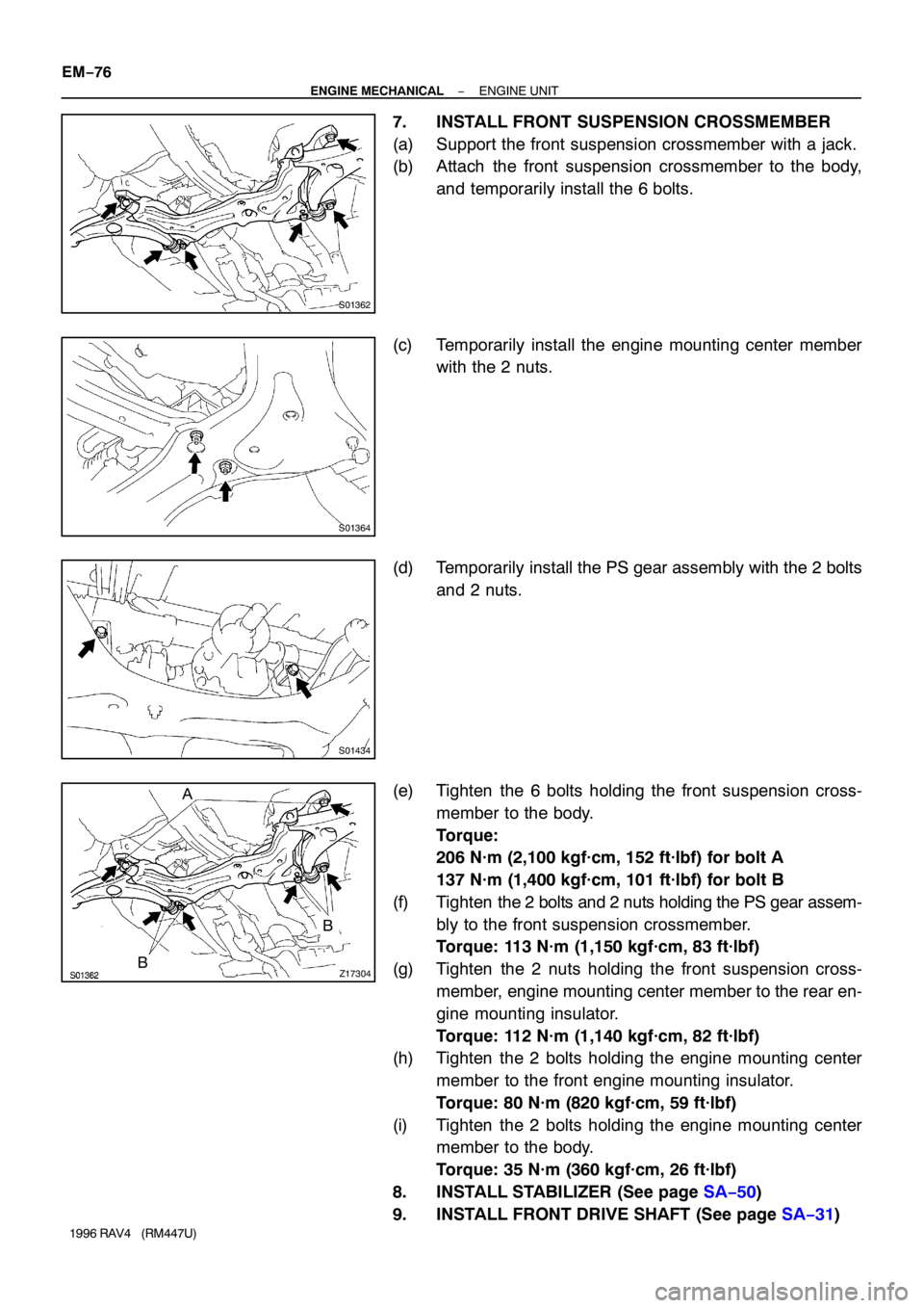
7. INSTALL FRONT SUSPENSION CROSSMEMBER
(a) Support the front suspension crossmember with a jack.
(b) Attach the front suspension crossmember to the body,
and temporarily install the 6 bolts.
(c) Temporarily install the engine mounting center member
with the 2 nuts.
(d) Temporarily install the PS gear assembly with the 2 bolts
and 2 nuts.
(e) Tighten the 6 bolts holding the front suspension cross-
member to the body.
Torque:
206 N·m (2,100 kgf·cm, 152 ft·lbf) for bolt A
137 N·m (1,400 kgf·cm, 101 ft·lbf) for bolt B
(f) Tighten the 2 bolts and 2 nuts holding the PS gear assem-
bly to the front suspension crossmember.
Torque: 113 N·m (1,150 kgf·cm, 83 ft·lbf)
(g) Tighten the 2 nuts holding the front suspension cross-
member, engine mounting center member to the rear en-
gine mounting insulator.
Torque: 112 N·m (1,140 kgf·cm, 82 ft·lbf)
(h) Tighten the 2 bolts holding the engine mounting center
member to the front engine mounting insulator.
Torque: 80 N·m (820 kgf·cm, 59 ft·lbf)
(i) Tighten the 2 bolts holding the engine mounting center
member to the body.
Torque: 35 N·m (360 kgf·cm, 26 ft·lbf)
8. INSTALL STABILIZER (See page SA−50)
9. INSTALL FRONT DRIVE SHAFT (See page SA−31)
Page 744 of 1354
S01797
M/T
A/T
S01785
A/T Only
S01351
M/T Only
Back−up Light
Connector EM−78
− ENGINE MECHANICALENGINE UNIT
1996 RAV4 (RM447U)
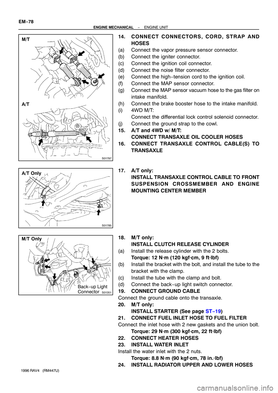
14. CONNECT CONNECTORS, CORD, STRAP AND
HOSES
(a) Connect the vapor pressure sensor connector.
(b) Connect the igniter connector.
(c) Connect the ignition coil connector.
(d) Connect the noise filter connector.
(e) Connect the high−tension cord to the ignition coil.
(f) Connect the MAP sensor connector.
(g) Connect the MAP sensor vacuum hose to the gas filter on
intake manifold.
(h) Connect the brake booster hose to the intake manifold.
(i) 4WD M/T:
Connect the differential lock control solenoid connector.
(j) Connect the ground strap to the cowl.
15. A/T and 4WD w/ M/T:
CONNECT TRANSAXLE OIL COOLER HOSES
16. CONNECT TRANSAXLE CONTROL CABLE(S) TO
TRANSAXLE
17. A/T only:
INSTALL TRANSAXLE CONTROL CABLE TO FRONT
SUSPENSION CROSSMEMBER AND ENGINE
MOUNTING CENTER MEMBER
18. M/T only:
INSTALL CLUTCH RELEASE CYLINDER
(a) Install the release cylinder with the 2 bolts.
Torque: 12 N·m (120 kgf·cm, 9 ft·lbf)
(b) Install the bracket with the bolt, and install the tube to the
bracket with the clamp.
(c) Install the tube with the clamp and bolt.
(d) Connect the back−up light switch connector.
19. CONNECT GROUND CABLE
Connect the ground cable onto the transaxle.
20. M/T only:
INSTALL STARTER (See page ST−19)
21. CONNECT FUEL INLET HOSE TO FUEL FILTER
Connect the inlet hose with 2 new gaskets and the union bolt.
Torque: 29 N·m (300 kgf·cm, 22 ft·lbf)
22. CONNECT HEATER HOSES
23. INSTALL WATER INLET
Install the water inlet with the 2 nuts.
Torque: 8.8 N·m (90 kgf·cm, 78 in.·lbf)
24. INSTALL RADIATOR UPPER AND LOWER HOSES
Page 997 of 1354
MX05N−02
Q10400
Air Intake Connector
Engine Coolant
Reservoir Tank Clutch Release Cylinder
and Line
Vehicle Speed
Sensor Connector
Back−Up Light Switch
Connector
Control Cable
Clip
Ground Cable
Transaxle Case Protector
Tie Rod End RH Drive Shaft
Stiffener PlateNo.2 Rear
End Plate
� Snap Ring
� Cotter Pin LH Drive
Shaft
PS Gear Assembly
Engine Mounting
Center Member
RH Engine
Under Cover
LH Engine Under CoverFront Suspension Crossmember
Assembly with Stabilizer BarClipAir Cleaner Case
Assembly
with Air Hose
Snap Ring
Engine
Wire
Clamp
� Cotter Pin
Lock Cap Starter
N·m (kgf·cm, ft·lbf): Specified torque
� Non−reusable part�
� �
4.9 (50, 43 in.·lbf)
12 (120, 9)
29 (300, 22)
35 (360, 26)32 (330, 24)46 (470, 34)
64 (650, 47)
35 (360, 26)
64 (650, 47)
12 (120, 9)
64 (650, 47)
25 (250, 18)
25 (250, 18)
9.0 (95, 78 in.·lbf)
37 (380, 27)
39 (400, 29)
9.0 (95, 78 in.·lbf)
29 (300, 22)
37 (380, 27)49 (500, 36)
113 (1,150, 83)
137 (1,400, 101)
206 (2,100, 152)
216 (2,200, 159)
113 (1,150, 83)
64 (650, 47)
48 (490, 35)
80 (820, 59)
115 (1,170, 85)
127 (1,300, 94)
�62 (630, 46)
Front Exhaust Pipe
� GasketClip
Washer
MX−2
− MANUAL TRANSAXLEMANUAL TRANSAXLE UNIT (2WD)
1996 RAV4 (RM447U)
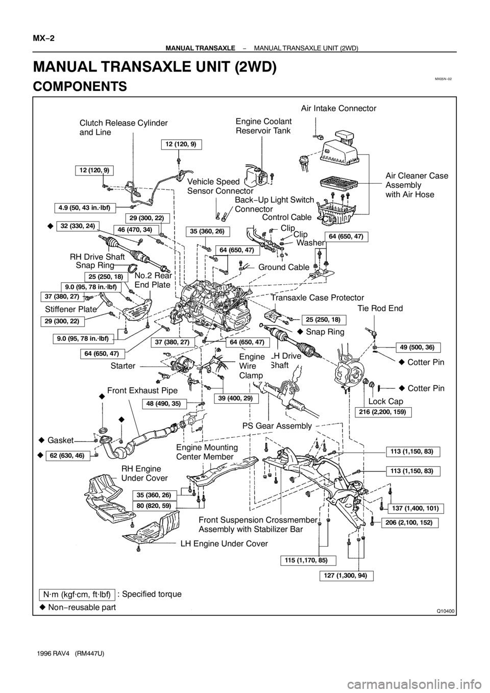
MANUAL TRANSAXLE UNIT (2WD)
COMPONENTS
Page 999 of 1354
Q08751
Q08752
Q10165
Filler Plug
Oil Level
0 − 5 mm
Drain Plug
Q08753
MX−4
− MANUAL TRANSAXLEMANUAL TRANSAXLE UNIT (2WD)
1996 RAV4 (RM447U)
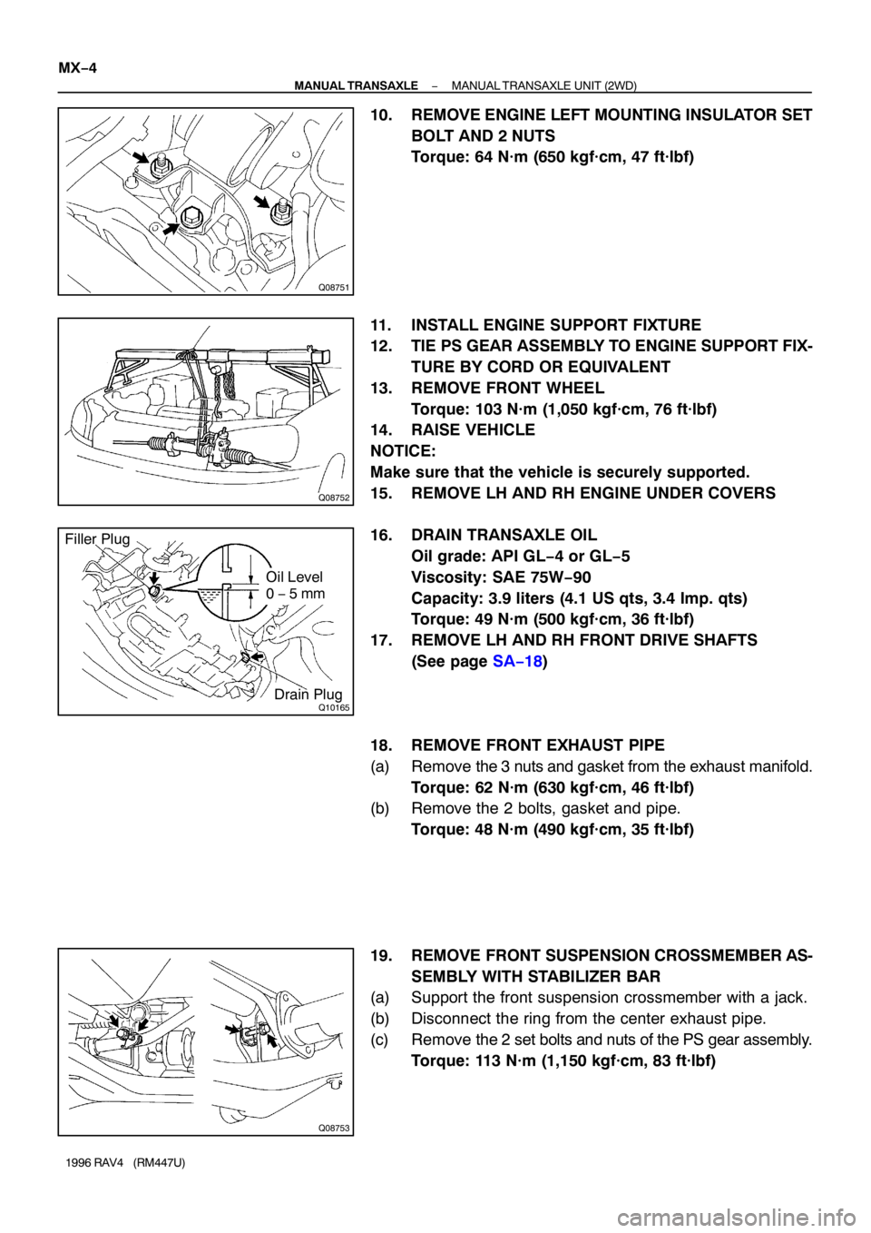
10. REMOVE ENGINE LEFT MOUNTING INSULATOR SET
BOLT AND 2 NUTS
Torque: 64 N·m (650 kgf·cm, 47 ft·lbf)
11. INSTALL ENGINE SUPPORT FIXTURE
12. TIE PS GEAR ASSEMBLY TO ENGINE SUPPORT FIX-
TURE BY CORD OR EQUIVALENT
13. REMOVE FRONT WHEEL
Torque: 103 N·m (1,050 kgf·cm, 76 ft·lbf)
14. RAISE VEHICLE
NOTICE:
Make sure that the vehicle is securely supported.
15. REMOVE LH AND RH ENGINE UNDER COVERS
16. DRAIN TRANSAXLE OIL
Oil grade: API GL−4 or GL−5
Viscosity: SAE 75W−90
Capacity: 3.9 liters (4.1 US qts, 3.4 Imp. qts)
Torque: 49 N·m (500 kgf·cm, 36 ft·lbf)
17. REMOVE LH AND RH FRONT DRIVE SHAFTS
(See page SA−18)
18. REMOVE FRONT EXHAUST PIPE
(a) Remove the 3 nuts and gasket from the exhaust manifold.
Torque: 62 N·m (630 kgf·cm, 46 ft·lbf)
(b) Remove the 2 bolts, gasket and pipe.
Torque: 48 N·m (490 kgf·cm, 35 ft·lbf)
19. REMOVE FRONT SUSPENSION CROSSMEMBER AS-
SEMBLY WITH STABILIZER BAR
(a) Support the front suspension crossmember with a jack.
(b) Disconnect the ring from the center exhaust pipe.
(c) Remove the 2 set bolts and nuts of the PS gear assembly.
Torque: 113 N·m (1,150 kgf·cm, 83 ft·lbf)
Page 1000 of 1354

Q08754
A
B A
B D
E
C
Q08755
Q08756DEC C
FG G
F
− MANUAL TRANSAXLEMANUAL TRANSAXLE UNIT (2WD)
MX−5
1996 RAV4 (RM447U)
(d) Remove the 2 nuts, 6 bolts and front suspension cross-
member assembly with the stabilizer bar.
Torque:
Bolt A: 206 N·m (2,100 kgf·cm, 152 ft·lbf)
Bolt B: 137 N·m (1,400 kgf·cm, 101 ft·lbf)
Nut C: 115 N·m (1,170 kgf·cm, 85 ft·lbf)
20. REMOVE ENGINE MOUNTING CENTER MEMBER
Remove the 4 bolts and center member.
Torque:
Bolt D: 80 N·m (820 kgf·cm, 59 ft·lbf)
Bolt E: 35 N·m (360 kgf·cm, 26 ft·lbf)
21. JACK UP TRANSAXLE SLIGHTLY
Using a trasmission jack, support the transaxle.
22. DISCONNECT ENGINE LEFT MOUNTING BRACKET
FROM ENGINE LEFT MOUNTING INSULATOR
Remove the set bolt of the engine left mounting bracket.
Torque: 64 N·m (650 kgf·cm, 47 ft·lbf)
23. REMOVE STIFFENER PLATE, NO.2 REAR END
PLATE AND TRANSAXLE LOWER SIDE MOUNTING
BOLT
(a) Remove the 2 bolts and stiffener plate.
Torque:
Bolt G: 37 N·m (380 kgf·cm, 27 ft·lbf)
(b) Remove the 7 bolts and No.2 rear end plate.
Torque:
Bolt C: 29 N·m (300 kgf·cm, 22 ft·lbf)
Bolt D: 46 N·m (470 kgf·cm, 34 ft·lbf)
Bolt E: 25 N·m (250 kgf·cm, 18 ft·lbf)
Bolt F: 9.0 N·m (95 kgf·cm, 78 in.·lbf)
24. REMOVE TRANSAXLE
Lower the engine left side and remove the transaxle from the
engine.
HINT:
At the time of installation, please refer to the following items.
�Align the input shaft with the clutch disc and install the
transaxle to the engine.
�Temporarily tighten the transaxle mounting bolts.
Page 1115 of 1354
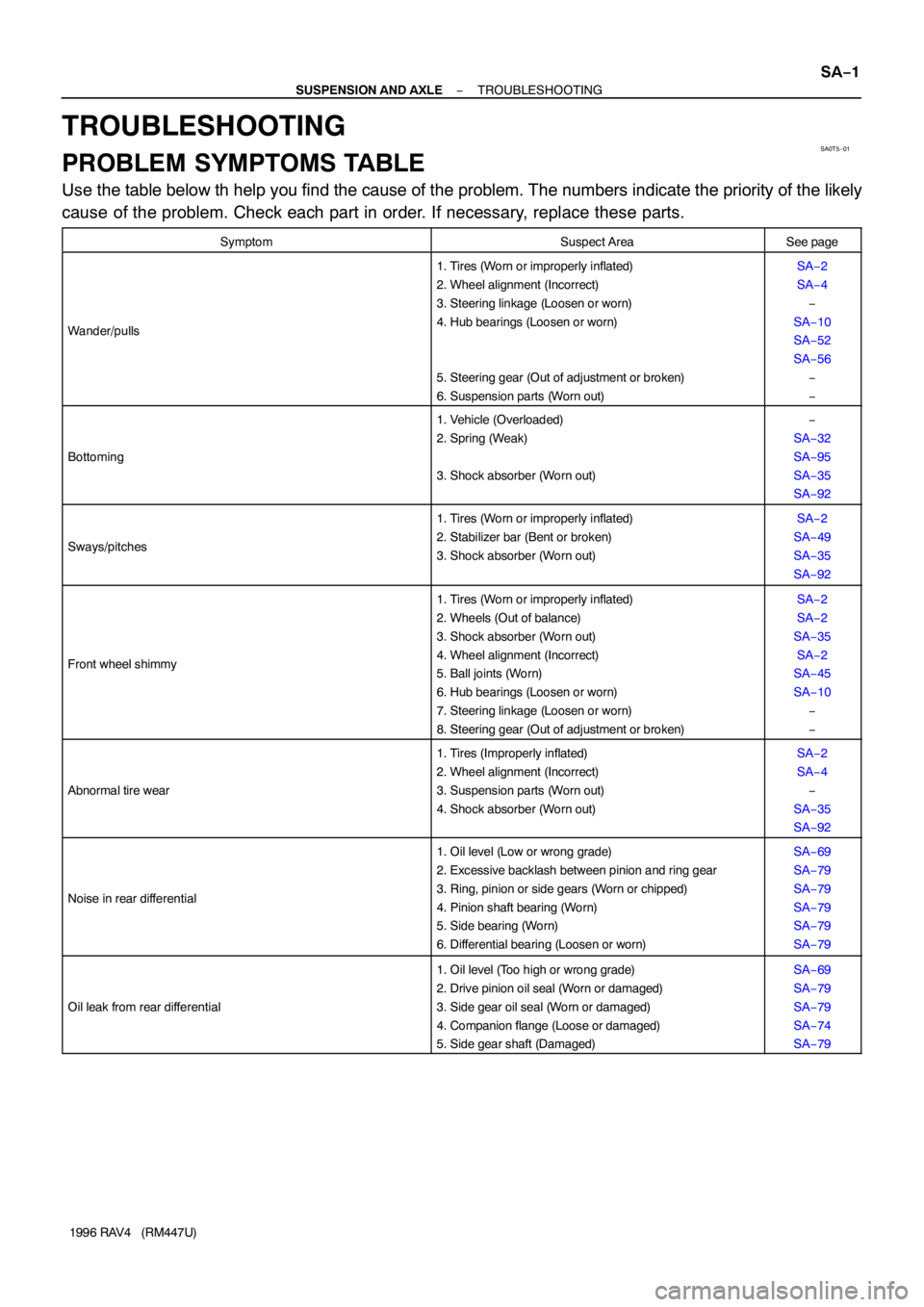
SA0T5−01
− SUSPENSION AND AXLETROUBLESHOOTING
SA−1
1996 RAV4 (RM447U)
TROUBLESHOOTING
PROBLEM SYMPTOMS TABLE
Use the table below th help you find the cause of the problem. The numbers indicate the priority of the likely
cause of the problem. Check each part in order. If necessary, replace these parts.
SymptomSuspect AreaSee page
Wander/pulls
1. Tires (Worn or improperly inflated)
2. Wheel alignment (Incorrect)
3. Steering linkage (Loosen or worn)
4. Hub bearings (Loosen or worn)
5. Steering gear (Out of adjustment or broken)
6. Suspension parts (Worn out)SA−2
SA−4
−
SA−10
SA−52
SA−56
−
−
Bottoming
1. Vehicle (Overloaded)
2. Spring (Weak)
3. Shock absorber (Worn out)−
SA−32
SA−95
SA−35
SA−92
Sways/pitches
1. Tires (Worn or improperly inflated)
2. Stabilizer bar (Bent or broken)
3. Shock absorber (Worn out)SA−2
SA−49
SA−35
SA−92
Front wheel shimmy
1. Tires (Worn or improperly inflated)
2. Wheels (Out of balance)
3. Shock absorber (Worn out)
4. Wheel alignment (Incorrect)
5. Ball joints (Worn)
6. Hub bearings (Loosen or worn)
7. Steering linkage (Loosen or worn)
8. Steering gear (Out of adjustment or broken)SA−2
SA−2
SA−35
SA−2
SA−45
SA−10
−
−
Abnormal tire wear
1. Tires (Improperly inflated)
2. Wheel alignment (Incorrect)
3. Suspension parts (Worn out)
4. Shock absorber (Worn out)SA−2
SA−4
−
SA−35
SA−92
Noise in rear differential
1. Oil level (Low or wrong grade)
2. Excessive backlash between pinion and ring gear
3. Ring, pinion or side gears (Worn or chipped)
4. Pinion shaft bearing (Worn)
5. Side bearing (Worn)
6. Differential bearing (Loosen or worn)SA−69
SA−79
SA−79
SA−79
SA−79
SA−79
Oil leak from rear differential
1. Oil level (Too high or wrong grade)
2. Drive pinion oil seal (Worn or damaged)
3. Side gear oil seal (Worn or damaged)
4. Companion flange (Loose or damaged)
5. Side gear shaft (Damaged)SA−69
SA−79
SA−79
SA−74
SA−79
Page 1116 of 1354
SA0T6−02
R03031
R14869
R07928
SA−2
− SUSPENSION AND AXLETIRE AND WHEEL
1996 RAV4 (RM447U)
TIRE AND WHEEL
INSPECTION
1. INSPECT TIRE
(a) Check the tires for wear and proper inflation pressure.
Cold tire inflation pressure
Tire sizeFront
kPa (kgf/cm2
or bar, psi)
Rear
kPa (kgf/cm2 or bar, psi)
3 Door vehicle
215/70R16 99S180 (1.8, 26)180 (1.8, 26)
5 Door vehicle
215/70R16 99S190 (1.9, 28)180 (1.8, 26)
(b) Check the tire runout.
Tire runout: 1.0 mm (0.039 in.) or less
2. ROTATING TIRES
HINT:
See the illustration for where to rotate each tire.
3. INSPECT WHEEL BALANCE
(a) Check and adjust the Off−the−car balance.
(b) If necessary, check and adjust the On−the−car−balance.
Imbalance after adjustment: 13.0 g (0.029 lb) or less