Page 311 of 1354

CO0BQ−03
S01355
S01278
w/ A/C
S01293
CO−16
− COOLINGRADIATOR
1996 RAV4 (RM447U)
REMOVAL
1. REMOVE ENGINE UNDER COVERS
2. DRAIN ENGINE COOLANT
3. w/ A/C:
REMOVE COOLER CONDENSER (See page AC−47)
4. REMOVE RADIATOR ASSEMBLY
(a) Disconnect the No.1 cooling fan connector.
(b) w/ A/C:
Disconnect the No.2 cooling fan connector.
(c) Disconnect the ECT switch connector for electric cooling
fan.
(d) Disconnect the engine wire clamp from No.1 cooling fan
shroud.
(e) Disconnect the upper radiator hose from radiator.
(f) Disconnect the lower radiator hose from radiator.
(g) Disconnect the radiator reservoir hose from radiator.
(h) Disconnect the 2 A/T oil cooler hoses from oil cooler
pipes.
(i) Remove the 2 bolts and 2 upper radiator supports.
Torque: 13 N·m (130 kgf·cm, 9 ft·lbf)
(j) Remove the radiator assembly.
HINT:
At the time of installation, plaese refer to the following items. Af-
ter installation, check that the rubber cushion (A) of the support
is not depressed.
(k) Remove the 2 lower radiator supports.
5. w/ A/C:
REMOVE NO.2 COOLING FAN FROM RADIATOR
Remove the 3 bolts and cooling fan.
Torque: 5.0 N·m (50 kgf·cm, 43 in.·lbf)
6. REMOVE NO.1 COOLING FAN FROM RADIATOR
Remove the 4 bolts and cooling fan.
Torque: 5.0 N·m (50 kgf·cm, 43 in.·lbf)
Page 314 of 1354
CO0BT−02
S01818
Radiator
No.1 Cooling Fan Lower Radiator Hose
No.2 Cooling
Fan Connector
(w/ A/C)
Upper Radiator
Support
Radiator Cap
Upper Radiator Hose
Engine Wire
Radiator Reservoir Hose
A/T Oil Cooler Hose
Drain Plug
� O−Ring
LH Engine
Under Cover ECT Switch
Connector
Radiator
Assembly
Cooler Condenser
Lower Radiator
Support
No.1 Cooling
Fan Connector
RH Engine
Under Cover
� Non−reusable PartA/T
M/TUpper Radiator
Support
LH Engine
Under Cover NO.1 COOLING FAN
− COOLINGELECTRIC COOLING FAN
CO−19
1996 RAV4 (RM447U)
COMPONENTS
Page 329 of 1354
P00495
Outside
Inside
− DIAGNOSTICSENGINE
DI−9
1996 RAV4 (RM447U)
4 Check air filter.
PREPARATION:
Remove air filter.
CHECK:
Visually check that the air cleaner element is not excessively
dirty or oily.
HINT:
If necessary, clean element with compressed air.
First blow from inside thoroughly,then blow from outside of ele-
ment.
NG Repair or replace.
OK
5 Check idle speed.
PREPARATION:
(a) Warm up engine to normal operating temperature.
(b) Switch off all accessories.
(c) Switch off air conditioning.
(d) Shift transmission into ”N” position.
(e) Connect the OBDII scan tool or TOYOTA hand−held tes-
ter to DLC3 on the vehicle.
CHECK:
Use CURRENT DATA to check the engine idle speed.
OK:
Idling speed: 650 − 750 rpm
NG Proceed to matrix chart of problem symptoms
on page DI−20.
OK
Page 373 of 1354

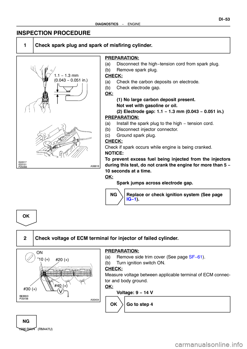
IG0317IG0151P25066A06618
1.1 − 1.3 mm
(0.043 − 0.051 in.)
A00404
”10 (+)
#30 (+)#40 (+) ON
#20 (+)
− DIAGNOSTICSENGINE
DI−53
1996 RAV4 (RM447U)
INSPECTION PROCEDURE
1 Check spark plug and spark of misfiring cylinder.
PREPARATION:
(a) Disconnect the high−tension cord from spark plug.
(b) Remove spark plug.
CHECK:
(a) Check the carbon deposits on electrode.
(b) Check electrode gap.
OK:
(1) No large carbon deposit present.
Not wet with gasoline or oil.
(2) Electrode gap: 1.1 − 1.3 mm (0.043 − 0.051 in.)
PREPARATION:
(a) Install the spark plug to the high − tension cord.
(b) Disconnect injector connector.
(c) Ground spark plug.
CHECK:
Check if spark occurs while engine is being cranked.
NOTICE:
To prevent excess fuel being injected from the injectors
during this test, do not crank the engine for more than 5 −
10 seconds at a time.
OK:
Spark jumps across electrode gap.
NG Replace or check ignition system (See page
IG−1).
OK
2 Check voltage of ECM terminal for injector of failed cylinder.
PREPARATION:
(a) Remove side trim cover (See page SF−61).
(b) Turn ignition switch ON.
CHECK:
Measure voltage between applicable terminal of ECM connec-
tor and body ground.
OK:
Voltage: 9 − 14 V
OK Go to step 4
NG
Page 379 of 1354

S02414
Distributor
Camshaft Position Sensor
(Built into Distributor)
D16
D16E4
E4
E4 1
B
R
W
G 1
2G4 5
17NE �
NE �
E1 ECM
Crankshaft Position Sensor2G �
W
− DIAGNOSTICSENGINE
DI−59
1996 RAV4 (RM447U)
DTC P0335 Crankshaft Position Sensor ”A” Circuit
Malfunction
CIRCUIT DESCRIPTION
Crankshaft position sensor (NE signal) consists of a signal plate and pickup coil.
The NE signal plate has 34 teeth and is mounted on the crankshaft. The NE signal sensor generates 34
signals for every engine revolution. The ECM detects the standard crankshaft angle based on the G signals,
and the actual crankshaft angle and the engine speed by the NE signals.
DTC No.DTC Detecting ConditionTrouble Area
P0335
No crankshaft position sensor signal to ECM during cranking
(2 trip detection logic)�Open or short in crankshaft position sensor circuit
�Crankshaft position sensor
�Starter
�ECM
No crankshaft position sensor signal to ECM with engine
speed 600 rpm or more
(2 trip detection logic)
WIRING DIAGRAM
DI3ZQ−01
Page 383 of 1354

− DIAGNOSTICSENGINE
DI−63
1996 RAV4 (RM447U)
DTC P0340 Camshaft Position Sensor Circuit
Malfunction
CIRCUIT DESCRIPTION
Camshaft position sensor (G signal) consist of a signal plate an pickup coil.
The G signal plate has one tooth on its outer circumference and is built into the distributor.
When the camshaft rotate, the protrusion on the signal plate and the air gap on the pickup coil change, caus-
ing fluctuations in the magnetic field and generating an electromotive force in the pickup coil.
The NE signal plate has 34 teeth and is mounted on the crankshaft. The NE signal sensor generates 34
signals for every engine revolution. The ECM detects the standard crankshaft angle based on the G signal
and the actual crankshaft angle and the engine speed by the NE signals.
DTC No.Detection ConditionTrouble Area
P0340No camshaft position sensor signal to ECM with engine speed
600 rpm or more
�Open or short in camshaft position sensor circuit
�Camshaft position sensor
�Starter
�ECM
WIRING DIAGRAM
Refer to page DI−59 for the WIRING DIAGRAM.
INSPECTION PROCEDURE
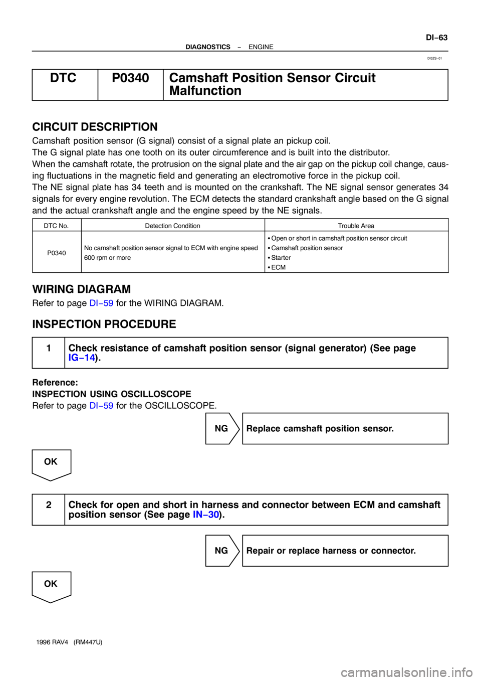
1 Check resistance of camshaft position sensor (signal generator) (See page
IG−14).
Reference:
INSPECTION USING OSCILLOSCOPE
Refer to page DI−59 for the OSCILLOSCOPE.
NG Replace camshaft position sensor.
OK
2 Check for open and short in harness and connector between ECM and camshaft
position sensor (See page IN−30).
NG Repair or replace harness or connector.
OK
DI3ZS−01
Page 420 of 1354

S07638
IG1
1H 1DI4I4
E4
E43 20
EA17
IG111
2221
20 8
1412
67
2
W B−WB−RB−R B−W
B−W
B−W
B−W
L−Y 4
53
2
1 Tr2
Igniter To Tachometer Distributor
BatteryFusible Link BlockR/B No.2
B−R IG Switch 4ECM
IGT
IGF5V
Tr1
AM2B
B−Y
Ignition Coil
J/B No.1
MAIN DI−100
− DIAGNOSTICSENGINE
1996 RAV4 (RM447U)
DTC P1300 Igniter Circuit Malfunction
CIRCUIT DESCRIPTION
This ECM determines the ignition timing, turns on Tr1 at a predetermined angle (°CA) before the desired
ignition timing and outputs an ignition signal (IGT) ”1” to the igniter.
Since the width of the IGT signal is constant, the dwell angle control circuit in the igniter determines the time
the control circuit starts primary current flow to the ignition coil based on the engine rpm and ignition timing
one revolution ago, that is, the time the Tr
2 turns on.
When it reaches the ignition timing, the ECM turns Tr
1 off and outputs the IGT signal ”O”.
This turns Tr
2 off, interrupting the primary current flow and generating a high voltage in the secondary coil
which causes the spark plug to spark. Also, by the counter electromotive force generated when the primary
current is interrupted, the igniter sends an ignition confirmation signal (IGF) to the ECM.
The ECM stops fuel injection as a fail safe function when the IGF signal is not input to the ECM.
DTC No.DTC Detecting ConditionTrouble Area
P1300No IGF signal to ECM for 8 consecutive IGT signals during
engine running.�Open or short in IGF or IGT circuit from igniter to ECM
�Igniter
�ECM
WIRING DIAGRAM
DI401−01
Page 423 of 1354

BE6653P23732A06621
START
IGT
(+)
BE6653P23909A07402
ON
3 (+) START
− DIAGNOSTICSENGINE
DI−103
1996 RAV4 (RM447U)
6 Disconnect igniter connector and check voltage between terminal IGT of ECM
connector and body ground.
PREPARATION:
(a) Disconnect the igniter connector.
(b) Remove side trim cover (See page SF−61).
CHECK:
Measure voltage between terminal IGT of ECM connector and
body ground when engine is cranked.
OK:
Voltage: More than 0.1 V and less than 4.5 V
OK Replace igniter.
NG
7 Check voltage between terminal 3 of igniter connector and body ground.
PREPARATION:
Disconnect the igniter connector.
CHECK:
Measure voltage between terminal 3 of igniter connector and
body ground, when ignition switch is turned to ”ON” and
”START” position.
OK:
Voltage: 9 − 14 V
NG Check and repair igniter power source circuit.
OK
8 Check for open and short in harness and connector between ignition switch and
ignition coil, ignition coil and igniter (See page IN−30).
NG Repair or replace harness or connector.
OK