Page 214 of 1354

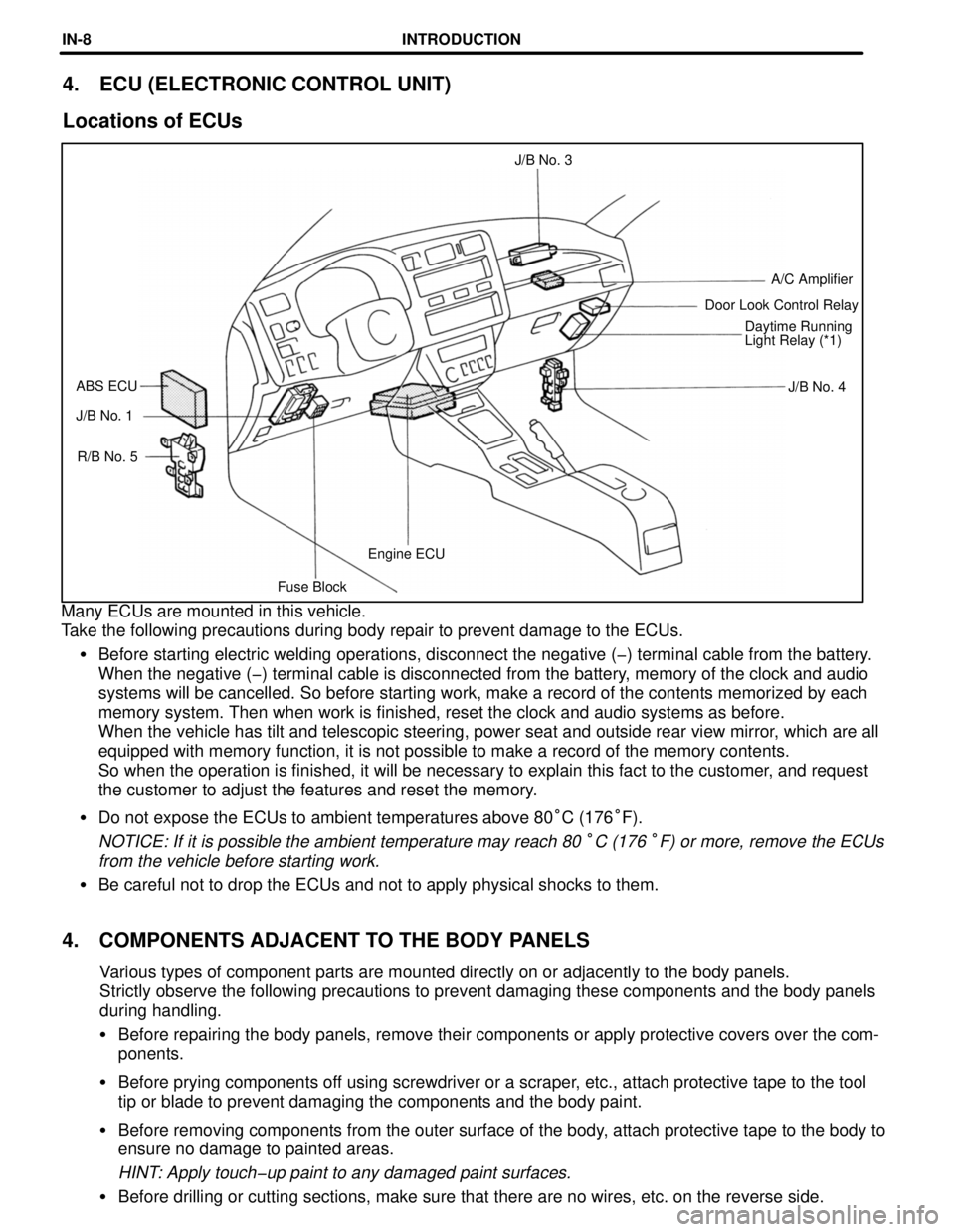
Fuse BlockEngine ECU R/B No. 5 J/B No. 1J/B No. 4 ABS ECUDaytime Running
Light Relay (*1) Door Look Control RelayA/C Amplifier J/B No. 3
4. ECU (ELECTRONIC CONTROL UNIT)
Locations of ECUs
Many ECUs are mounted in this vehicle.
Take the following precautions during body repair to prevent damage to the ECUs.
�Before starting electric welding operations, disconnect the negative (-) terminal cable from the battery.
When the negative (-) terminal cable is disconnected from the battery, memory of the clock and audio
systems will be cancelled. So before starting work, make a record of the contents memorized by each
memory system. Then when work is finished, reset the clock and audio systems as before.
When the vehicle has tilt and telescopic steering, power seat and outside rear view mirror, which are all
equipped with memory function, it is not possible to make a record of the memory contents.
So when the operation is finished, it will be necessary to explain this fact to the customer, and request
the customer to adjust the features and reset the memory.
�Do not expose the ECUs to ambient temperatures above 80°C (176°F).
NOTICE: If it is possible the ambient temperature may reach 80 °C (176 °F) or more, remove the ECUs
from the vehicle before starting work.
�Be careful not to drop the ECUs and not to apply physical shocks to them.
4. COMPONENTS ADJACENT TO THE BODY PANELS
Various types of component parts are mounted directly on or adjacently to the body panels.
Strictly observe the following precautions to prevent damaging these components and the body panels
during handling.
�Before repairing the body panels, remove their components or apply protective covers over the comœ
ponents.
�Before prying components off using screwdriver or a scraper, etc., attach protective tape to the tool
tip or blade to prevent damaging the components and the body paint.
�Before removing components from the outer surface of the body, attach protective tape to the body to
ensure no damage to painted areas.
HINT: Apply touch-up paint to any damaged paint surfaces.
�Before drilling or cutting sections, make sure that there are no wires, etc. on the reverse side.
INTRODUCTIONINœ8
Page 689 of 1354

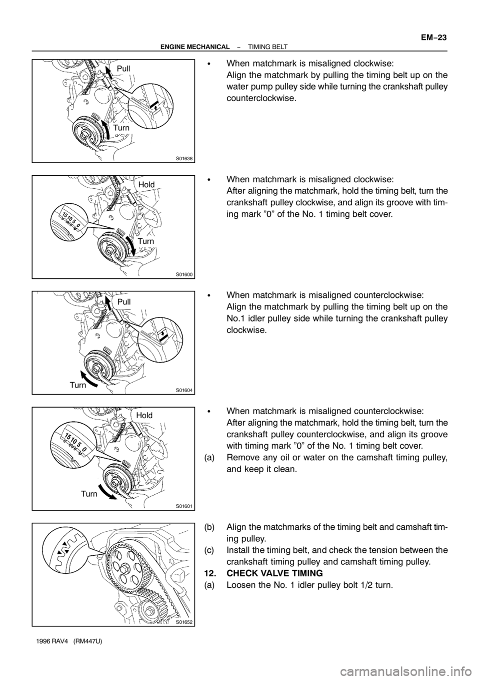
S01638
Turn
Pull
S01600
Hold
Turn
S01604
Pull
Turn
S01601
TurnHold
S01652
− ENGINE MECHANICALTIMING BELT
EM−23
1996 RAV4 (RM447U)
�When matchmark is misaligned clockwise:
Align the matchmark by pulling the timing belt up on the
water pump pulley side while turning the crankshaft pulley
counterclockwise.
�When matchmark is misaligned clockwise:
After aligning the matchmark, hold the timing belt, turn the
crankshaft pulley clockwise, and align its groove with tim-
ing mark ”0” of the No. 1 timing belt cover.
�When matchmark is misaligned counterclockwise:
Align the matchmark by pulling the timing belt up on the
No.1 idler pulley side while turning the crankshaft pulley
clockwise.
�When matchmark is misaligned counterclockwise:
After aligning the matchmark, hold the timing belt, turn the
crankshaft pulley counterclockwise, and align its groove
with timing mark ”0” of the No. 1 timing belt cover.
(a) Remove any oil or water on the camshaft timing pulley,
and keep it clean.
(b) Align the matchmarks of the timing belt and camshaft tim-
ing pulley.
(c) Install the timing belt, and check the tension between the
crankshaft timing pulley and camshaft timing pulley.
12. CHECK VALVE TIMING
(a) Loosen the No. 1 idler pulley bolt 1/2 turn.
Page 690 of 1354

S01602
Turn
S01597
S01603
Turn
S01238
P25229
Length = 735 mm (28.94 in.)
Length = 230 mm (9.06 in.) EM−24
− ENGINE MECHANICALTIMING BELT
1996 RAV4 (RM447U)
(b) Slowly turn the crankshaft pulley 2 revolutions from TDC
to TDC.
NOTICE:
Always turn the crankshaft clockwise.
(c) Check that each pulley aligns with the timing marks as
shown in the illustration.
If the timing marks do not align, remove the timing belt and rein-
stall it.
(d) Slowly turn the crankshaft pulley 1 and 7/8 revolutions,
and align its groove with the mark at 45 ° BTDC (for No.
1 cylinder) of the No.1 timing belt cover.
NOTICE:
Always turn the crankshaft clockwise.
(e) Torque the mounting bolt of the No.1 idler pulley.
Torque: 42 N·m (425 kgf·cm, 31 ft·lbf)
13. PLACE RH ENGINE MOUNTING BRACKET IN POSI-
TION
HINT:
Do not install the bolts.
14. INSTALL NO. 2 TIMING BELT COVER
(a) Check that the timing belt cover gaskets has no cracks or
peeling, etc.
If the gasket has cracks or peeling, etc., replace it using these
steps:
�Using a screwdriver and gasket scraper, remove all
the old gasket material.
�Thoroughly clean all components to remove all the
loose material.
Page 706 of 1354
P05613
P05614
TurnB
A
P05615
P05616
(1)
(2)
(3) EM−40
− ENGINE MECHANICALCYLINDER HEAD
1996 RAV4 (RM447U)
33. DISASSEMBLE EXHAUST CAMSHAFT
(a) Mount the camshaft in a vise.
NOTICE:
Be careful not to damage the camshaft.
(b) Insert service bolt A into the service hole of the camshaft
sub gear.
(c) Using a screwdriver, turn the sub gear clockwise, and re-
move service bolt B.
NOTICE:
Be careful not to damage the camshaft.
(d) Using snap ring pliers, remove the snap ring.
(e) Remove the wave washer (1), camshaft sub gear (2) and
camshaft gear spring (3).
Page 723 of 1354

P05618
Turn
ADrive Gear
Sub−Gear B
S01778
80 − 11 5°
Knock
Pin
S01790
EM3373
2 − 3 mm
(0.08 − 0.12 in.)
Seal
Packing
− ENGINE MECHANICALCYLINDER HEAD
EM−57
1996 RAV4 (RM447U)
(c) Using snap ring pliers, install the snap ring.
(d) Insert a service bolt A into the service hole of the camshaft
sub gear.
(e) Using a screwdriver, align the holes of the camshaft drive
gear and sub gear by turning camshaft sub gear clock-
wise, and install a service bolt B.
NOTICE:
Be careful not to damage the camshaft.
(f) Align the gear teeth of the drive gear and sub gear, and
tighten the service bolt B.
9. INSTALL CAMSHAFTS
NOTICE:
Since the thrust clearance of the camshaft is small, the
camshaft must be kept level while it is being installed. If the
camshaft is not kept level, the portion of the cylinder head
receiving the shaft thrust may crack or be damaged, caus-
ing the camshaft to seize or break. To avoid this, the follow-
ing steps should be carried out.
(a) Install the intake camshaft.
(1) Apply MP grease to the thrust portion of the cam-
shaft.
(2) Place the intake camshaft at 80 − 11 5° BTDC of
camshaft angle on the cylinder head.
HINT:
The above angle arrows the No. 1 and No. 3 cylinder cam lobes
of the intake camshaft to push their valve lifters evenly.
(3) Apply MP grease to a new oil seal lip.
(4) Install the oil seal as far as the deepest part of the
cylinder head.
(5) Apply seal packing to the No. 1 bearing cap as
shown.
Seal packing: Part No. 08826−00080 or equivalent
Page 724 of 1354

S01770
S01772
9
10 3
45
61
27
8
S01776
10 − 45°
Knock
Pin
S01773
Assembly
Timing Reference
Mark
Mark EM−58
− ENGINE MECHANICALCYLINDER HEAD
1996 RAV4 (RM447U)
(6) Install the bearing caps in their proper locations.
(7) Apply a light coat of engine oil on the threads and
under the heads of the bearing cap bolts.
(8) Install and uniformly tighten the 10 bearing cap
bolts, in several passes, in the sequence shown.
Torque: 19 N·m (190 kgf·cm, 14 ft·lbf)
(b) Install the exhaust camshaft.
(1) Set the knock pin of the intake camshaft at 10 − 45°
BTDC of camshaft angle.
HINT:
The above angle allows the No. 2 and No. 4 cylinder cam lobes
of the exhaust camshaft to push their valve lifters evenly.
(2) Apply MP grease to the thrust portion of the cam-
shaft.
(3) Engage the exhaust camshaft gear to the intake
camshaft gear by matching the timing marks on
each gear.
(4) Roll down the exhaust camshaft onto the bearing
journals while engaging gears with each other.
NOTICE:
There are also assembly reference marks on each gear as
shown in the illustration. Do not use these marks.
(5) Turn the intake camshaft clockwise or counterclock-
wise a little until the exhaust camshaft sits in the
bearing journals evenly without rocking the cam-
shaft on the bearing journals.
NOTICE:
It is very important to replace the camshaft in the bearing
journals evenly while tightening bearing caps in the subse-
quent steps.
Page 800 of 1354
30
G ELECTRICAL WIRING ROUTING
Position of Parts in Instrument Panel
A 12 A/C Amplifier C 6 Cigarette Lighter Illumination
A 13 A/C Control SW C 7 Clock
A 14 A/C Thermistor C 8 Clutch Start SW
A 15 ABS Deceleration Sensor C 9 Combination Meter
A 16 ABS ECU C 10 Combination Meter
A 17 ABS ECU C 11 Combination Meter
A 18 Airbag Sensor Assembly C 12 Combination SW
A 19 Airbag Squib (Front Passenger Airbag Assembly) C 13 Combination SW
A 20 Airbag Squib (Steering Wheel Pad) C 14 Combination SW
C 15 Cruise Control Clutch SW
B 3 Blower Motor C 16 Cruise Control ECU
B 4 Blower Resisitor
B 5 Blower SW D 2 Data Link Connector 3
B 6 Buckle SW LH D 3 Defroster Mode SW
D 4 Diode (Engine Idle-Up)
C 4 Center Diff. Lock Control SW D 5 Door Lock Control Relay
C 5 Cigarette Lighter
Page 854 of 1354
85
B 6
BH ID
W-B
W-B W-B
W-B
W-BSW
ROL SW
LLED TRANSM ISSIO NG
G
G
G
(
M/T)
G
(
A/T)
GG
G
G
G
(
M/T)
(
A/T)
W-B
W-B
W-B
W-B GG
G
W-B
5 1
2 3
6 2
323
1 4
TAILLIGHT LH
[REA R C O M B. L IG H T L H] R 8
W-B
W-BG
CLOCK C 7
REAR WINDOW DEFOGGER R 5
HAZARD SW H 4
CENTER DIFF. LOCK CONT C 4
ELECTRONICALLY CONTRO
PATTERN SELECT SW E 3 JUNCTION
CONNECTER J10
B
W-B
2
1 2
REAR SIDE MARKER LIGHT LH R10
G
1H 71I 9
B