Page 53 of 1354
N18087
”O” Reading Temporary
Pawl
Temporary PawlView A View A
Z17544
Beam Angle Gauge
(Horizontal Direction)
FrontAcceptable Range”O” Reading
Adjusting
Screw B Holder Assembly BE−18
− BODY ELECTRICALHEADLIGHT AND TAILLIGHT SYSTEM
1996 RAV4 (RM447U)
(c) Insert the holder assembly, unlock in step (b), to the screw
and housing again.
HINT:
When the assembly is inserted till the pawl for temporary set is
hooded to the cross slit of the housing as shown in view A, set-
ting is completed.
(d) Turn the adjusting screw B to the left and adjust the LH
and RH headlight aims.
(e) Pull the holder assembly backwards and lock it.
Page 54 of 1354
BE0J9−05
− BODY ELECTRICALTURN SIGNAL AND HAZARD WARNING SYSTEM
BE−19
1996 RAV4 (RM447U)
TURN SIGNAL AND HAZARD WARNING SYSTEM
LOCATION
Page 55 of 1354

BE0JA−01
Z17622
Right
Left
1 2 3
Z07679
2 4
5 1 3
7 96
8 10
BE1843
3
2
1 BE−20
− BODY ELECTRICALTURN SIGNAL AND HAZARD WARNING SYSTEM
1996 RAV4 (RM447U)
INSPECTION
1. INSPECT TURN SIGNAL SWITCH CONTINUITY
Switch positionTester connectionSpecified condition
Left turn1 − 2Continuity
Neutral−No continuity
Right turn2 − 3Continuity
If continuity is not as specified, replace the switch.
2. INSPECT HAZARD WARNING SWITCH CONTINUITY
Switch positionTester connectionSpecified condition
Switch OFF7 − 10Continuity
Switch ON4 − 5 − 6 − 9
7 − 8Continuity
Illumination circuit2 − 3Continuity
If continuity is not as specified, replace the switch.
3. INSPECT TURN SIGNAL FLASHER OPERATION
(a) Connect the positive (+) lead from the battery to terminal
2 and the negative (−) lead to terminal 3.
(b) Connect the 2 turn signal light bulbs parallel to each other
to terminals 1 and 3, check that the bulbs flash.
HINT:
The turn signal lights should flash 60 or 120 times per minute.
If one of the front or rear turn signal lights has an open circuit,
the number of flashing will be more than 140 per minute.
If operation is not as specified, replace the flasher.
Page 56 of 1354
BE0JD−05
BE−24
− BODY ELECTRICALBACK−UP LIGHT SYSTEM
1996 RAV4 (RM447U)
BACK−UP LIGHT SYSTEM
LOCATION
Page 57 of 1354
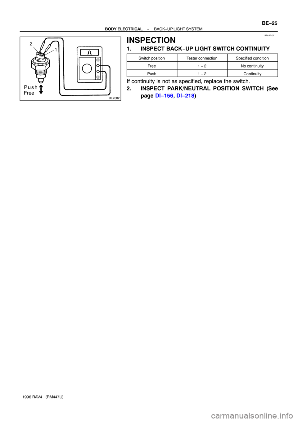
BE2682
Push
Free2
1
BE0JE−02
− BODY ELECTRICALBACK−UP LIGHT SYSTEM
BE−25
1996 RAV4 (RM447U)
INSPECTION
1. INSPECT BACK−UP LIGHT SWITCH CONTINUITY
Switch positionTester connectionSpecified condition
Free1 − 2No continuity
Push1 − 2Continuity
If continuity is not as specified, replace the switch.
2. INSPECT PARK/NEUTRAL POSITION SWITCH (See
page DI−156, DI−218)
Page 58 of 1354
BE0JF−06
BE−26
− BODY ELECTRICALSTOP LIGHT SYSTEM
1996 RAV4 (RM447U)
STOP LIGHT SYSTEM
LOCATION
Page 59 of 1354
BE0JG−01
Z05647
1
2
43
1
4 2
3
− BODY ELECTRICALSTOP LIGHT SYSTEM
BE−27
1996 RAV4 (RM447U)
INSPECTION
INSPECT STOP LIGHT SWITCH CONTINUITY
Switch positionTester connectionSpecified condition
Switch pin free
(Pedal depressed)1 − 2Continuity
Switch pin pushed in
(Pedal released)3 − 4No continuity
If continuity is not as specified, replace the switch.
Page 60 of 1354
BE0JH−06
BE−28
− BODY ELECTRICALWIPER AND WASHER SYSTEM
1996 RAV4 (RM447U)
WIPER AND WASHER SYSTEM
LOCATION