Page 376 of 1354
P19750
Knock Sensor 1
E1 KNKECM
10
E5 B
1 DI−56
− DIAGNOSTICSENGINE
1996 RAV4 (RM447U)
DTC P0325 Knock Sensor 1 Circuit Malfunction
CIRCUIT DESCRIPTION
A knock sensor is fitted to the cylinder block to detect engine knocking. This sensor contains a piezoelectric
element which generates a voltage when it becomes deformed, which occurs when the cylinder block vi-
brates due to knocking. If engine knocking occurs, ignition timing is retarded to suppress it.
DTC No.DTC Detecting ConditionTrouble Area
P0325No knock sensor 1 signal to ECM with engine speed 1,200 rpm
or more (2 trip detection logic)�Open or short in knock sensor 1 circuit
�Knock sensor 1 (looseness)
�ECM
If the ECM detects the above diagnosis conditions, it operates the fail safe function in which the corrective
retard angle value is set to the maximum value.
WIRING DIAGRAM
DI3ZP−01
Page 377 of 1354
BE6053S02469A07399
LOCK
E5 ConnectorKNK
(+)
− DIAGNOSTICSENGINE
DI−57
1996 RAV4 (RM447U)
INSPECTION PROCEDURE
1 Check continuity between terminal KNK of ECM connector and body ground.
PREPARATION:
(a) Remove side trim cover (See page SF−61).
(b) Disconnect the E5 connector of ECM.
CHECK:
Measure resistance between terminal KNK of ECM connector
and body ground.
OK:
Resistance: 1M Ω or higher
OK Go to step 3.
NG
2 Check knock sensor (See page SF−57).
NG Repair knock sensor.
OK
3 Check for open and short in harness and connector between ECM and knock
sensor (See page IN−30).
NG Repair or replace harness or connector.
OK
4 Does malfunction disappear when a good knock sensor is installed?
YES Replace knock sensor.
NO
Page 378 of 1354
A00406
0.5 V/
Division
0.5 V/
Division5 m sec./Division Knock signal waveform
0 V
0 V
100 μ sec./Division DI−58
− DIAGNOSTICSENGINE
1996 RAV4 (RM447U)
Check and replace ECM (See page IN−30).
Reference INSPECTION USING OSCILLOSCOPE
�With the engine racing (4,000 rpm) measure between ter-
minal KNK of ECM and body ground.
HINT:
The correct waveform is as shown.
�Spread the time on the horizontal axis, and confirm that
period of the wave is 132
sec.
(Normal mode vibration frequency of knock sensor: 7.6
KHz).
HINT:
If normal mode vibration frequency is not 7.6 KHz, the sensor
is malfunctioning.
Page 379 of 1354

S02414
Distributor
Camshaft Position Sensor
(Built into Distributor)
D16
D16E4
E4
E4 1
B
R
W
G 1
2G4 5
17NE �
NE �
E1 ECM
Crankshaft Position Sensor2G �
W
− DIAGNOSTICSENGINE
DI−59
1996 RAV4 (RM447U)
DTC P0335 Crankshaft Position Sensor ”A” Circuit
Malfunction
CIRCUIT DESCRIPTION
Crankshaft position sensor (NE signal) consists of a signal plate and pickup coil.
The NE signal plate has 34 teeth and is mounted on the crankshaft. The NE signal sensor generates 34
signals for every engine revolution. The ECM detects the standard crankshaft angle based on the G signals,
and the actual crankshaft angle and the engine speed by the NE signals.
DTC No.DTC Detecting ConditionTrouble Area
P0335
No crankshaft position sensor signal to ECM during cranking
(2 trip detection logic)�Open or short in crankshaft position sensor circuit
�Crankshaft position sensor
�Starter
�ECM
No crankshaft position sensor signal to ECM with engine
speed 600 rpm or more
(2 trip detection logic)
WIRING DIAGRAM
DI3ZQ−01
Page 380 of 1354
FI7059FI7060A06620
NENEG
G20 m sec./Division (Idling)
10 m sec./Division (Idling)
5 V/Division
5 V/Division
DI−60
− DIAGNOSTICSENGINE
1996 RAV4 (RM447U)
INSPECTION PROCEDURE
1 Check resistance of crankshaft position sensor (See page IG−14).
Reference:
INSPECTION USING OSCILLOSCOPE
During cranking or idling, check between terminals G � and NE
�, NE � and NE � of ECM.
HINT:
The correct waveforms are as shown.
NG Replace crankshaft position sensor.
OK
2 Check for open and short in harness and connector between ECM and crank-
shaft position sensor (See page IN−30).
NG Repair or replace harness or connector.
OK
Page 381 of 1354
− DIAGNOSTICSENGINE
DI−61
1996 RAV4 (RM447U)
3 Inspect sensor installation and teeth of signal plate.
NG Tighten the sensor.
Replace signal plate.
OK
Check and replace ECM (See page IN−30).
Page 382 of 1354
DI−62
− DIAGNOSTICSENGINE
1996 RAV4 (RM447U)
DTC P0336 Crankshaft Position Sensor Circuit Range /
Performance
CIRCUIT DESCRIPTION
Refer to Crankshaft Position Sensor ”A” Circuit Malfunction on page DI−59.
DTC No.DTC Detecting ConditionTrouble Area
P0336Engine control computer malfunction (for backup)�Distributor
�ECM
WIRING DIAGRAM
Refer to page DI−59.
INSPECTION PROCEDURE
1 Are there any other codes (besides DTC P0336) being output?
YES Go to relevant DTC chart.
NO
Check and replace ECM
(See page IN−30).
DI3ZR−01
Page 383 of 1354

− DIAGNOSTICSENGINE
DI−63
1996 RAV4 (RM447U)
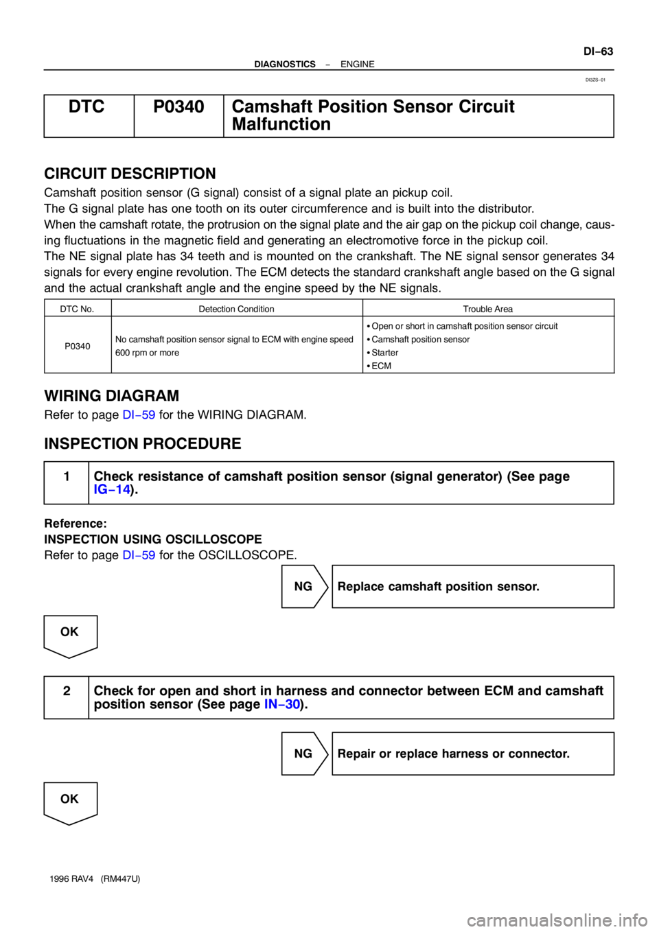
DTC P0340 Camshaft Position Sensor Circuit
Malfunction
CIRCUIT DESCRIPTION
Camshaft position sensor (G signal) consist of a signal plate an pickup coil.
The G signal plate has one tooth on its outer circumference and is built into the distributor.
When the camshaft rotate, the protrusion on the signal plate and the air gap on the pickup coil change, caus-
ing fluctuations in the magnetic field and generating an electromotive force in the pickup coil.
The NE signal plate has 34 teeth and is mounted on the crankshaft. The NE signal sensor generates 34
signals for every engine revolution. The ECM detects the standard crankshaft angle based on the G signal
and the actual crankshaft angle and the engine speed by the NE signals.
DTC No.Detection ConditionTrouble Area
P0340No camshaft position sensor signal to ECM with engine speed
600 rpm or more
�Open or short in camshaft position sensor circuit
�Camshaft position sensor
�Starter
�ECM
WIRING DIAGRAM
Refer to page DI−59 for the WIRING DIAGRAM.
INSPECTION PROCEDURE
1 Check resistance of camshaft position sensor (signal generator) (See page
IG−14).
Reference:
INSPECTION USING OSCILLOSCOPE
Refer to page DI−59 for the OSCILLOSCOPE.
NG Replace camshaft position sensor.
OK
2 Check for open and short in harness and connector between ECM and camshaft
position sensor (See page IN−30).
NG Repair or replace harness or connector.
OK
DI3ZS−01