Page 112 of 1399

INSPECTION
1. INSPECT ILLUMINATION OPERATION
Connect the positive (+)")
AC2SM−01
AC2717
Connector ”A”
−
AIR CONDITIONING AIR CONDITIONING CONTROL ASSEMBLY
AC−69
1996 LAND CRUISER (RM451U)
INSPECTION
1. INSPECT ILLUMINATION OPERATION
Connect the positive (+) lead from the battery to terminal A −13
and the negative ( −) lead to terminal A−3, then check that the
illuminations light up.
If illuminations do not light up, test the bulb.
2. Air Inlet Control Switch:
INSPECT INDICATOR LIGHT OPERATION
(a) Connect the positive (+) lead from the battery to terminal
A−9 and the negative ( −) lead to terminal A−8.
(b) With the air inlet control button pushed in, check that the FRESH or RECIRC indicator light lights up.
(c) Next, push in the button again, and check that the indica-
tor light goes off and the other indicator light lights up.
AICSwitch
.-20-2-CN06571 .-18-2-B
ModeControlSwitch
2=i=~~~:=i~;=j::;5-H--+__Blower Speed
ControlSwitch
TemperatureControl
Switch Connector
"A"
~~.~r-r""""~~~9&ru7 6ill'O'~5 •U3 2
1
20 19iJl
II1716115a1311121110...... L.....-~
Connector"B"
,...,.....-~~'is"'-"'r"""".~~r"'-&765~'o"~•3ru2I
1&17iJl1615ullJ12IliJllO9L...,..L-,_\-L..,-
Z04530
r
!rfl176~54 3 21~
m2019lI:8171611514131211~
Connector"A"
~e@j
AC2718
Brought to you by BirfMark
Brought to you by BirfMark
Version 1.11 - 03/16/2010
Page 113 of 1399

AC2722
Connector ”A”Connector ”B”
AC2723
Connector ”A”
Connector ”B”
AC2722
Connector ”A”
Connector ”B”
AC2723
Connector ”A”
Connector ”B”
AC−70
−
AIR CONDITIONING AIR CONDITIONING CONTROL ASSEMBLY
1996 LAND CRUISER (RM451U)
(d) Then connect the positive (+) lead from the battery to ter-
minal A−13 and check that the indicator dims.
If operation is not as specified, replace the A/C control assem-
bly.
3. Mode Control Switch: INSPECT INDICATOR LIGHT OPERATION
(a) Connect the positive (+) lead from the battery to terminal A−9 and the negative ( −) lead to terminal B−16.
(b) Push each of the mode buttons in and check that their in- dicator light lights up.
(c) Then connect the positive (+) lead from the battery to ter-
minal A−13 and check that the indicator dims.
If operation is not as specified, replace the A/C control assem-
bly.
4. Blower Speed Control Switch: INSPECT INDICATOR LIGHT OPERATION
(a) Connect the positive (+) lead from the battery to terminal A−9 and the negative ( −) lead to terminal B−16.
(b) Push each of the blower speed control buttons in and check that their indicator light lights up.
(c) Then connect the positive (+) lead from the battery to ter-
minal A−13 and check that the indicator dims.
If operation is not as specified, replace the A/C control assem-
bly.
c
r
1rf1~716[lJ';W5413 211
1\E~g1~171611514[.3]12111~
-r...'onnector"A"(
IeCBI
AC2719
Brought to you by BirfMark
Brought to you by BirfMark
Version 1.11 - 03/16/2010
Page 277 of 1399
BO48O−01
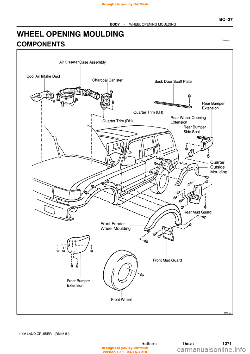
Front Fender
Wheel Moulding
Quarter
Outside
Moulding
−
BODY WHEEL OPENING MOULDING
BO−37
1271
Author�: Date�:
1996 LAND CRUISER (RM451U)
WHEEL OPENING MOULDING
COMPONENTS
Brought to you by BirfMark
Brought to you by BirfMark
Version 1.11 - 03/16/2010
Page 671 of 1399
DI5Q0−02
Vehicle Brought to Workshop
Customer Problem Analysis
Warning Light Check
DTC Check and Recording
DTC ChartDI−243
Circuit Inspection
Remains on
Symptom SimulationDTC Check and Recording
Identification of Problem
Malfunction Code Clearance
Confirmation Test
Malfunction Code
END
Normal Code
Normal Code
1
2
3 7
8
Repair
10 6
5
Step
:Diagnostic steps permitting the use
of the TOYOTA hand−held tester.
3, 4, 5, 10, 11, 12
DI−239
DI−240
DI−271
DI−240
DI−240
DI−240
Malfunction Code Clearance4
DI−240
9
DTC Check11
DI−240
12 Does Not Light Up
Normal Code
Normal
Code
Malfunction Code
Malfunction Code
Malfunction Code
IN−18
DI−238
−
DIAGNOSTICS SUPPLEMENTAL RESTRAINT SYSTEM
405
Author�: Date�:
1996 LAND CRUISER (RM451U)
SUPPLEMENTAL RESTRAINT SYSTEM
HOW TO PROCEED WITH TROUBLESHOOTING
Perform troubleshoot in accordance with the procedure on the following page.
Brought to you by BirfMark
Brought to you by BirfMark
Version 1.11 - 03/16/2010
Page 676 of 1399

DIAGNOSTIC TROUBLE CODE CHART
If a malfunction code is displayed during the DTC check, the circuit listed")
DI5Q3−02
−
DIAGNOSTICS SUPPLEMENTAL RESTRAINT SYSTEM
DI−243
1996 LAND CRUISER (RM451U)
DIAGNOSTIC TROUBLE CODE CHART
If a malfunction code is displayed during the DTC check, the circuit listed for that code in t\
he table below
(Proceed to the page given for that circuit.).
DTC No.
(See Page)Detection ItemTrouble AreaSRS
Warning Light
Normal
( DI−271 )�System normal−OFF
�Source voltage drop�Battery
� Airbag sensor assemblyON
11
( DI−247 )
�Short in squib circuit (to ground)�Steering wheel pad (D squib)
� Front passenger airbag assembly (P squib )
� Spiral cable
� Airbag sensor assembly
� Wire harness
ON
12
( DI−254 )
�Short in squib circuit (to B+)�Steering wheel pad (D squib)
� Front passenger airbag assembly (P squib)
� Spiral cable
� Airbag sensor assembly
� Wire harness
ON
14
( DI−260 )
�Open in D squib circuit�Steering wheel pad (D squib)
� Spiral cable
� Airbag sensor assembly
� Wire harness
ON
31
( DI−265 )�Airbag sensor assembly malfunction�Airbag sensor assemblyON
54
( DI−267 )�Open in P squib circuit�Front passenger airbag assembly (P squib)
� Airbag sensor assembly
� Wire harness
ON
HINT:
�When the SRS warning light remains lit up and the DTC is the normal code\
, this means a source drop
voltage.
This malfunction is not stored in memory by the airbag sensor assembly a\
nd if the power source volt-
age returns to normal, the SRS warning light will automatically go out.
�When 2 or more codes are indicated, the codes will be displayed in numer\
al order starting from the
lowest numbered code.
�If a code not listed on the chart is displayed, the airbag sensor assemb\
ly is faulty.
Brought to you by BirfMark
Brought to you by BirfMark
Version 1.11 - 03/16/2010
Page 681 of 1399
R05901
R14290H00004
Airbag Sensor
Assembly
P Squib
D Squib Spiral
Cable
D+
D−
DI−248
−
DIAGNOSTICS SUPPLEMENTAL RESTRAINT SYSTEM
1996 LAND CRUISER (RM451U)
INSPECTION PROCEDURE
1 Preparation. (See step 1 on page DI−271)
2 Check D squib circuit.
CHECK:
For the connector (on the spiral cable side) between the spiral
cable and steering wheel pad, measure the resistance between
D
+, D− and body ground.
OK:
Resistance: 1 MΩ or Higher
NG Go to step 7.
OK
Brought to you by BirfMark
Brought to you by BirfMark
Version 1.11 - 03/16/2010
Page 687 of 1399

(−)
DI−254
−
DIAGNOSTICS SUPPLEMENTAL RESTRAINT SYSTEM
1996 LAND CRUISER (RM451U)
DTC 12 Short i")
AB0119
W01931
R14300
H00010
Airbag Sensor
Assembly
Spiral
Cable
ON
P Squib
D Squib D+
D−
(+)
(−)
DI−254
−
DIAGNOSTICS SUPPLEMENTAL RESTRAINT SYSTEM
1996 LAND CRUISER (RM451U)
DTC 12 Short in Squib Circuit (to B+)
CIRCUIT DESCRIPTION
The squib circuit consists of the airbag sensor assembly, spiral cable, steering wheel pad and front passen-
ger airbag assembly. It causes the SRS to deploy when the SRS deployment conditions are sat\
isfied.
For details of the function of each component, see page FUNCTION OF COMP\
ONENTS on page RS−2.
DTC 12 is recorded when a B+ short is detected in the squib circuit.
DTC No.DTC Detection ConditionTrouble Area
12
� Short circuit in squib wire harness (to B+)
� Squib malfunction
� Spiral cable malfunction
� Airbag sensor assembly malfunction�Steering wheel pad (D squib)
� Front passenger airbag assembly (P squib)
� Spiral cable
� Airbag sensor assembly
� Wire harness
WIRING DIAGRAM
Refer to page DI−247 for the WIRING DIAGRAM.
INSPECTION PROCEDURE
1 Preparation. (See step 1 on page DI−271)
2 Check D squib circuit.
CHECK:
For the connector (on the spiral cable side) between the spiral
cable and steering wheel pad, measure the voltage between
D
+, D− and body ground.
OK:
Voltage: 0 V
NG Go to step 7.
OK
DI5Q8−03
Brought to you by BirfMark
Brought to you by BirfMark
Version 1.11 - 03/16/2010
Page 693 of 1399

DTC 14 Open in D Squib Circuit
CIRCUIT DESC")
R15194
Airbag Sensor
Assembly
Spiral
Cable
D Squib
1
2 3 4
W
B D
+
D−
DI−260
−
DIAGNOSTICS SUPPLEMENTAL RESTRAINT SYSTEM
1996 LAND CRUISER (RM451U)
DTC 14 Open in D Squib Circuit
CIRCUIT DESCRIPTION
The D squib circuit consists of the airbag sensor assembly, spiral cable and the steering wheel pad.
It causes the airbag to deploy when the airbag deployment conditions are\
satisfied.
For details of the function of each component, see FUNCTION OF COMPONENT\
S on page RS−2.
DTC 14 is recorded when an open is detected in the squib circuit.
DTC No.DTC Detection ConditionTrouble Area
14
� Open circuit in D+ wire harness or D− wire harness of
squib
� D squib malfunction
� Spiral cable malfunction
� Center airbag sensor assembly malfunction�Steering wheel pad (D squib)
� Spiral cable
� Airbag sensor assembly
� Wire harness
WIRING DIAGRAM
INSPECTION PROCEDURE
1 Preparation. (See step 1 on page DI−271)
DI5Q9−03
Brought to you by BirfMark
Brought to you by BirfMark
Version 1.11 - 03/16/2010


INSPECTION PROCEDURE
1 Preparation.")