Page 787 of 1399

EM−2
−
ENGINE MECHANICAL CO/HC
505
Author�: Date�:
1996 LAND CRUISER (RM451U)
6. TROUBLESHOOTING
If the CO/HC concentration does not comply with regulations,
troubleshoot in the order given below.
See the table below for possible causes, and then inspect and
correct the applicable causes if necessary.
COHCProblemsCauses
NormalHighRough idle
3. Faulty ignitions:
�Incorrect timing
� Fouled, shorted or improperly gapped plugs
� Open or crossed high −tension cords
� Cracked distributor cap
4. Incorrect valve clearance
5. Leaky EGR valve
6. Leaky intake and exhaust valves
7. Leaky cylinders
LowHighRough idle
(Fluctuating HC reading)
1. Vacuum leaks:
� PCV hose
� EGR valve
� Intake manifold
� Air intake chamber
� Throttle body
� IAC valve
� Brake booster line
2. Lean mixture causing misfire
HighHighRough idle
(Black smoke from exhaust)
1. Restricted air filter
2. Faulty SFI systems:
� Faulty pressure regulator
� Clogged fuel return line
� Defective ECT sensor
� Faulty ECM
� Faulty injector
� Faulty throttle position sensor
� Faulty MAF meter
Brought to you by BirfMark
Brought to you by BirfMark
Version 1.11 - 03/16/2010
Page 788 of 1399

EM0KR−04
−
ENGINE MECHANICAL COMPRESSION
EM−3
506
Author�: Date�:
1996 LAND CRUISER (RM451U)
COMPRESSION
INSPECTION
HINT:
If there is lack of power, excessive oil consumption or poor fuel
economy, measure the compression pressure.
1. WARM UP AND STOP ENGINE
Allow the engine to warm up to normal operating temperature.
2. DISCONNECT DISTRIBUTOR CONNECTOR
3. REMOVE SPARK PLUGS (See page IG−1 )
4. CHECK CYLINDER COMPRESSION PRESSURE
(a) Insert a compression gauge into the spark plug hole.
(b) Fully open the throttle.
(c) While cranking the engine, measure the compression pressure.
HINT:
Always use a fully charged battery to obtain engine speed of
250 rpm or more.
(d) Repeat steps (a) through (c) for each cylinder.
NOTICE:
This measurement must be done in as short a time as pos-
sible. Compression pressure:
1,176 kPa (12.0 kgf/cm
2, 171 psi) or more
Minimum pressure: 883 kPa (9.0 kgf/cm
2, 128 psi)
Difference between each cylinder:
98 kPa (1.0 kgf/cm
2, 14 psi) or less
If the cylinder compression in one or more cylinders is low, pour
a small amount of engine oil into the cylinder through the spark
plug hole and repeat steps (a) through (c) for cylinders with low
compression.
�If adding oil helps the compression, it is likely that
the piston rings and/or cylinder bore are worn or
damaged.
�If pressure stays low, a valve may be sticking or
seating is improper, or there may be leakage past
the gasket.
5. REINSTALL SPARK PLUGS (See page IG−1 )
6. RECONNECT DISTRIBUTOR CONNECTOR
Brought to you by BirfMark
Brought to you by BirfMark
Version 1.11 - 03/16/2010
Page 813 of 1399

EM1E3−01
EM−28
−
ENGINE MECHANICAL CYLINDER HEAD
1996 LAND CRUISER (RM451U)
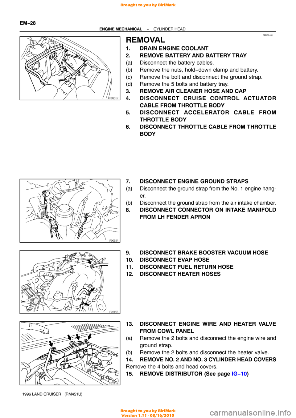
REMOVAL
1. DRAIN ENGINE COOLANT
2. REMOVE BATTERY AND BATTERY TRAY
(a) Disconnect the battery cables.
(b) Remove the nuts, hold −down clamp and battery.
(c) Remove the bolt and disconnect the ground strap.
(d) Remove the 5 bolts and battery tray.
3. REMOVE AIR CLEANER HOSE AND CAP
4. DISCONNECT CRUISE CONTROL ACTUATOR CABLE FROM THROTTLE BODY
5. DISCONNECT ACCELERATOR CABLE FROM
THROTTLE BODY
6. DISCONNECT THROTTLE CABLE FROM THROTTLE BODY
7. DISCONNECT ENGINE GROUND STRAPS
(a) Disconnect the ground strap from the No. 1 engine hang-
er.
(b) Disconnect the ground strap from the air intake chamber.
8. DISCONNECT CONNECTOR ON INTAKE MANIFOLD FROM LH FENDER APRON
9. DISCONNECT BRAKE BOOSTER VACUUM HOSE
10. DISCONNECT EVAP HOSE
11. DISCONNECT FUEL RETURN HOSE
12. DISCONNECT HEATER HOSES
13. DISCONNECT ENGINE WIRE AND HEATER VALVE FROM COWL PANEL
(a) Remove the 2 bolts and disconnect the engine wire and
ground strap.
(b) Remove the 2 bolts and disconnect the heater valve.
14. REMOVE NO. 2 AND NO. 3 CYLINDER HEAD COVERS
Remove the 4 bolts and head covers.
15. REMOVE DISTRIBUTOR (See page IG−10 )
Brought to you by BirfMark
Brought to you by BirfMark
Version 1.11 - 03/16/2010
Page 814 of 1399

−
ENGINE MECHANICAL CYLINDER HEAD
EM−29
1996 LAND CRUISER (RM451U)
16. DISCONNECT PS RESERVOIR TANK
Remove the 3 bolts and disconnect the reservoir tank.
17. DISCONNECT RADIATOR INLET HOSE
18. DISCONNECT NO. 3 WATER BYPASS HOSE
19. REMOVE GENERATOR (See page CH−8 )
20. REMOVE THROTTLE BODY (See page SF−45)
21. REMOVE OIL DIPSTICKS AND GUIDES FOR ENGINE AND TRANSMISSION
(a) Remove the 2 mounting bolts.
(b) Pull out the dipstick together with dipstick guide.
(c) Remove the O−ring from the dipstick guide.
22. REMOVE INTAKE MANIFOLD STAY
Remove the 2 bolts and intake manifold stay.
23. DISCONNECT FUEL INLET HOSE
Remove the union bolt and 2 gaskets, and disconnect the fuel
inlet hose from the fuel filter.
24. DISCONNECT ENGINE WIRE
(a) Disconnect the connectors. (1) Disconnect the ECT sender gauge connector.
(2) Disconnect the ECT cut switch connector.
(3) Disconnect the ECT sensor connector.
(4) Disconnect the knock sensor connector.
(5) Disconnect the crankshaft position sensor connec-tor.
(6) Remove the bolt and disconnect the engine wire from the cylinder block.
Brought to you by BirfMark
Brought to you by BirfMark
Version 1.11 - 03/16/2010
Page 822 of 1399
EM1E4−01
−
ENGINE MECHANICAL CYLINDER HEAD
EM−37
1996 LAND CRUISER (RM451U)
DISASSEMBLY
1. REMOVE GENERATOR BRACKET
Remove the 2 bolts and generator bracket.
2. REMOVE WATER OUTLET
Remove the 2 nuts, water outlet and gasket.
3. REMOVE EGR PIPE
(a) Loosen the union nut.
(b) Remove the 2 bolts, EGR pipe and gasket.
4. REMOVE HEATER INLET PIPE AND HOSE
Remove the 2 bolts, and disconnect the pipe and hose.
5. REMOVE AIR INTAKE CHAMBER AND INTAKE MAN-
IFOLD ASSEMBLY
(a) Disconnect the 2 vacuum hoses from the TVV.
(b) Remove the 10 bolts, 2 nuts, intake manifold and gasket.
6. DISASSEMBLE AIR INTAKE CHAMBER AND INTAKE MANIFOLD ASSEMBLY
(a) Disconnect the vacuum sensing hose from the fuel pres-
sure regulator.
(b) Remove the 6 bolts, 2 nuts, air intake chamber and 2 gas-
kets from the intake manifold.
7. REMOVE NO. 1 WATER BYPASS HOSE
Brought to you by BirfMark
Brought to you by BirfMark
Version 1.11 - 03/16/2010
Page 838 of 1399

−
ENGINE MECHANICAL CYLINDER HEAD
EM−53
1996 LAND CRUISER (RM451U)
(d) Using a plastic−faced hammer, lightly tap the valve stem
tip to ensure a proper fit.
7. INSTALL VALVE LIFTERS AND SHIMS
(a) Install the valve lifter and shim.
(b) Check that the valve lifter rotates smoothly by hand.
8. INSTALL ACCELERATOR CABLE BRACKET AND THROTTLE CABLE BRACKET
9. INSTALL 2 ENGINE WIRE CLAMP BRACKETS
10. INSTALL NO. 1 AND NO. 2 ENGINE HANGERS Torque: 41 N·m (420 kgf·cm, 30 ft·lbf)
11. INSTALL NO. 1 WATER BYPASS HOSE
12. ASSEMBLE AIR INTAKE CHAMBER AND INTAKE MANIFOLD ASSEMBLY
(a) Install 2 new gaskets and the air intake chamber with the
6 bolts and 2 nuts.
Torque: 21 N·m (210 kgf·cm, 15 ft·lbf)
(b) Connect the vacuum sensing hose to the fuel pressure regulator.
13. INSTALL AIR INTAKE CHAMBER AND INTAKE MAN- IFOLD ASSEMBLY
(a) Place a new gasket so that the rear mark is toward the rear side.
(b) Install the intake manifold with the 10 bolts and 2 nuts.
Torque: 21 N·m (210 kgf·cm, 15 ft·lbf)
(c) Connect the 2 vacuum hoses to the TVV.
14. INSTALL HEATER INLET PIPE AND HOSE
Install the heater hose to the cylinder head, and connect the
pipe to the intake manifold with the 2 bolts. Torque: 21 N·m (210 kgf·cm, 15 ft·lbf)
15. INSTALL EGR PIPE
(a) Temporarily install the union nut to the EGR valve.
(b) Install a new gasket and the EGR pipe to the cylinder head with the 2 bolts.
Torque: 21 N·m (210 kgf·cm, 15 ft·lbf)
(c) Tighten the union nut. Torque: 78 N·m (800 kgf·cm, 58 ft·lbf)
16. INSTALL WATER OUTLET
Install a new gasket and the water outlet with the 2 nuts. Torque: 21 N·m (210 kgf·cm, 15 ft·lbf)
17. INSTALL GENERATOR BRACKET
Install the generator bracket with the 2 bolts. Torque: 43 N·m (440 kgf·cm, 32 ft·lbf)
Brought to you by BirfMark
Brought to you by BirfMark
Version 1.11 - 03/16/2010
Page 847 of 1399

EM−62
−
ENGINE MECHANICAL CYLINDER HEAD
1996 LAND CRUISER (RM451U)
(h) Connect the engine wire to the intake manifold and cylin-
der block with the 2 bolts.
(i) Connect the PNP switch connector.
(j) Connect the 2 heated oxygen sensor connectors.
(k) Connect the connectors.
(1) Connect the Knock sensor connector.
(2) Connect the oil level sensor connector.
(3) Connect the 2 connectors to tthe ransmission.
(4) Connect the starter connector.
(l) Connect the engine wire to the cylinder block with the bolt.
(m) Connect the connectors.
(1) Connect the ECT sender gauge connector.
(2) Connect the ECT cut switch connector.
(3) Connect the ECT sensor connector.
(4) Connect the knock sensor connector.
(5) Connect the crankshaft position sensor connector.
19. CONNECT FUEL INLET HOSE
Connect the fuel inlet hose to the fuel filter with 2 new gaskets
and the union bolt. Torque: 29 N·m (300 kgf·cm, 22 ft·lbf)
20. INSTALL INTAKE MANIFOLD STAY
Install the intake manifold stay with the 2 bolts. Torque: 36 N·m (360 kgf·cm, 26 ft·lbf)
21. INSTALL OIL DIPSTICKS AND GUIDES FOR ENGINE AND TRANSMISSION
(a) Install a new O−ring to the dipstick guide.
(b) Apply a light coat of engine oil on the O −ring.
(c) Push in the dipstick guide into the guide hole of the oil pan.
(d) Install the dipstick guide with the 2 bolts. Torque: 20 N·m (200 kgf·cm, 14 ft·lbf)
22. INSTALL THROTTLE BODY (See page SF−48)
23. INSTALL GENERATOR AND DRIVE BELTS (See page CH−19 )
Brought to you by BirfMark
Brought to you by BirfMark
Version 1.11 - 03/16/2010
Page 848 of 1399

−
ENGINE MECHANICAL CYLINDER HEAD
EM−63
1996 LAND CRUISER (RM451U)
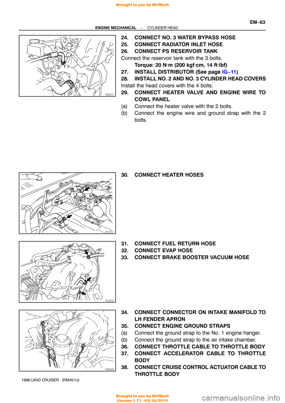
24. CONNECT NO. 3 WATER BYPASS HOSE
25. CONNECT RADIATOR INLET HOSE
26. CONNECT PS RESERVOIR TANK
Connect the reservoir tank with the 3 bolts.
Torque: 20 N·m (200 kgf·cm, 14 ft·lbf)
27. INSTALL DISTRIBUTOR (See page IG−11)
28. INSTALL NO. 2 AND NO. 3 CYLINDER HEAD COVERS
Install the head covers with the 4 bolts.
29. CONNECT HEATER VALVE AND ENGINE WIRE TO COWL PANEL
(a) Connect the heater valve with the 2 bolts.
(b) Connect the engine wire and ground strap with the 2 bolts.
30. CONNECT HEATER HOSES
31. CONNECT FUEL RETURN HOSE
32. CONNECT EVAP HOSE
33. CONNECT BRAKE BOOSTER VACUUM HOSE
34. CONNECT CONNECTOR ON INTAKE MANIFOLD TO LH FENDER APRON
35. CONNECT ENGINE GROUND STRAPS
(a) Connect the ground strap to the No. 1 engine hanger.
(b) Connect the ground strap to the air intake chamber.
36. CONNECT THROTTLE CABLE TO THROTTLE BODY
37. CONNECT ACCELERATOR CABLE TO THROTTLE
BODY
38. CONNECT CRUISE CONTROL ACTUATOR CABLE TO
THROTTLE BODY
Brought to you by BirfMark
Brought to you by BirfMark
Version 1.11 - 03/16/2010