Page 980 of 1399
PP2XY−02
−
PREPARATION TRANSFER
PP−39
1996 LAND CRUISER (RM451U)
SSM (Special Service Materials)
08826−00090Seal Packing 1281,
THREE BOND 1281 or equivalent
(FIPG)Front case x Rear case
Rear case x Case cover
Case x Extension housing
08833−00070Adhesive 1324,
THREE BOND 1324 or equivalentDynamic damper set bolt
08833−00080Adhesive 1344
THREE BOND 1344
LOCTITE 242 or equivalentStraight screw plug
Case cover set bolt
Brought to you by BirfMark
Brought to you by BirfMark
Version 1.11 - 03/16/2010
Page 983 of 1399
PP3KP−01
PP−42
−
PREPARATION SUSPENSION AND AXLE
91
Author�: Date�:
1996 LAND CRUISER (RM451U)
SUSPENSION AND AXLE
SST (Special Service Tools)
09214−76011Crankshaft Pulley ReplacerFront differential
Rear differential
09223−15020Oil Seal & Bearing ReplacerFront differential
Rear axle
09226−10010Crankshaft Front & Rear Bearing
ReplacerRear suspension
09308−00010Oil Seal PullerFront axle
Front differential
Rear axle
Rear differential
09308−10010Oil Seal PullerFront differential
Rear differential
09315−00022Clutch Release Bearing Remover
& ReplacerRear differential
09316−20011Transfer Bearing ReplacerRear suspension
09316−60011Transmission & Transfer Bearing
ReplacerFront differential
Rear differential
(09316−00011)Replacer Pipe
(09316−00021)Replacer ”A”
(09316−00051)Replacer ”D”
09330−00021Companion Flange Holding ToolFront differential
Rear differential
Brought to you by BirfMark
Brought to you by BirfMark
Version 1.11 - 03/16/2010
Page 1018 of 1399
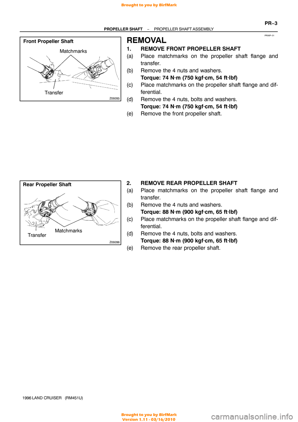
PR06P−01
Z09285
Matchmarks
Transfer
Front Propeller Shaft
Z09286
Matchmarks
Transfer
Rear Propeller Shaft
−
PROPELLER SHAFT PROPELLER SHAFT ASSEMBLY
PR−3
1996 LAND CRUISER (RM451U)
REMOVAL
1. REMOVE FRONT PROPELLER SHAFT
(a) Place matchmarks on the propeller shaft flange and
transfer.
(b) Remove the 4 nuts and washers. Torque: 74 N·m (750 kgf·cm, 54 ft·lbf)
(c) Place matchmarks on the propeller shaft flange and dif-
ferential.
(d) Remove the 4 nuts, bolts and washers. Torque: 74 N·m (750 kgf·cm, 54 ft·lbf)
(e) Remove the front propeller shaft.
2. REMOVE REAR PROPELLER SHAFT
(a) Place matchmarks on the propeller shaft flange and
transfer.
(b) Remove the 4 nuts and washers. Torque: 88 N·m (900 kgf·cm, 65 ft·lbf)
(c) Place matchmarks on the propeller shaft flange and dif- ferential.
(d) Remove the 4 nuts, bolts and washers. Torque: 88 N·m (900 kgf·cm, 65 ft·lbf)
(e) Remove the rear propeller shaft.
Brought to you by BirfMark
Brought to you by BirfMark
Version 1.11 - 03/16/2010
Page 1057 of 1399
RS0PE−01
−
SUPPLEMENTAL RESTRAINT SYSTEM AIRBAG SENSOR ASSEMBLY
RS−33
1996 LAND CRUISER (RM451U)
REMOVAL
NOTICE:
Do not open the cover or the case of the ECU and various
computers unless absolutely necessary.
(If the IC terminals are touched, the IC may be destroyed by
static electricity.)
1. REMOVE THESE PARTS:
(a) Transfer shirt knob
(b) Front console box
2. REMOVE AIRBAG SENSOR ASSEMBLY
(a) Disconnect the connector.
NOTICE:
Remove the connector with the sensor assembly installed.
(b) Using a torx wrench remove the 4 screws and the airbag sensor assembly.
Torx wrench: T40 (Part No. 09042 −00020 or locally
manufactured tool)
Brought to you by BirfMark
Brought to you by BirfMark
Version 1.11 - 03/16/2010
Page 1164 of 1399
SA1VL−03
−
SUSPENSION AND AXLE DIFFERENTIAL LOCKING SYSTEM
SA−101
958
Author�: Date�:
1996 LAND CRUISER (RM451U)
DIFFERENTIAL LOCKING SYSTEM
ON−VEHICLE INSPECTION
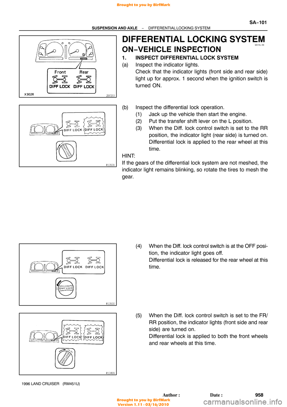
1. INSPECT DIFFERENTIAL LOCK SYSTEM
(a) Inspect the indicator lights.
Check that the indicator lights (front side and rear side)
light up for approx. 1 second when the ignition switch is
turned ON.
(b) Inspect the differential lock operation. (1) Jack up the vehicle then start the engine.
(2) Put the transfer shift lever on the L position.
(3) When the Diff. lock control switch is set to the RR
position, the indicator light (rear side) is turned on.
Differential lock is applied to the rear wheel at this
time.
HINT:
If the gears of the differential lock system are not meshed, the
indicator light remains blinking, so rotate the tires to mesh the
gear.
(4) When the Diff. lock control switch is at the OFF posi-
tion, the indicator light goes off.
Differential lock is released for the rear wheel at this
time.
(5) When the Diff. lock control switch is set to the FR/ RR position, the indicator lights (front side and rear
side) are turned on.
Differential lock is applied to both the front wheels
and rear wheels at this time.
Brought to you by BirfMark
Brought to you by BirfMark
Version 1.11 - 03/16/2010
Page 1309 of 1399
SS−8
−
SERVICE SPECIFICATIONS ENGINE MECHANICAL
1996 LAND CRUISER (RM451U)
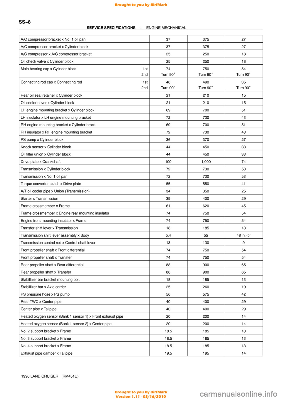
A/C compressor bracket x No. 1 oil pan
3737527
A/C compressor bracket x Cylinder block3737527
A/C compressor x A/C compressor bracket2525018
Oil check valve x Cylinder block2525018
Main bearing cap x Cylinder block
1st
2nd74
Turn 90°750
Turn 90°54
Turn 90°
Connecting rod cap x Connecting rod 1st
2nd48
Turn 90°490
Turn 90°35
Turn 90°
Rear oil seal retainer x Cylinder block2121015
Oil cooler cover x Cylinder block2121015
LH engine mounting bracket x Cylinder block6970051
LH insulator x LH engine mounting bracket7273043
RH engine mounting bracket x Cylinder brock6970051
RH insulator x RH engine mounting bracket7273043
PS pump x Cylinder block3637027
Knock sensor x Cylinder block4445033
Oil filter union x Cylinder block4445033
Drive plate x Crankshaft1001,00074
Transmission x Cylinder block7273053
Transmission x No. 1 oil pan7273053
Torque converter clutch x Drive plate5555041
A/T oil cooler pipe x Union (Transmission)3435025
Starter x Transmission3940029
Frame crossmember x Frame6162045
Frame crossmember x Engine rear mounting insulator7475054
Engine front mounting insulator x Frame7475054
Transfer shift lever x Transmission1818513
Transmission shift lever assembly x Body5.45548 in.·lbf
Transmission control rod x Control shaft lever131309
Front propeller shaft x Front dif ferential7475054
Front propeller shaft x Transfer7475054
Rear propeller shaft x Rear differential8890065
Rear propeller shaft x Transfer8890065
Stabillizer bar bracket mounting bolt1818513
Stabillizer bar x Axle carrier2526019
PS pressure hose x PS pump5657542
Rear TWC x Center pipe4040029
Center pipe x Tailpipe4040029
Heated oxygen sensor (Bank 1 sensor 1) x Front exhaust pipe2020014
Heated oxygen sensor (Bank 1 sensor 2) x Center pipe2020014
No. 2 support bracket x Frame18.518513
No. 3 support bracket x Frame18.518513
No. 4 support bracket x Frame18.518513
Exhaust pipe damper x Tailpipe19.519514
Brought to you by BirfMark
Brought to you by BirfMark
Version 1.11 - 03/16/2010
Page 1325 of 1399
SS1E7−01
SS−24
−
SERVICE SPECIFICATIONS AUTOMATIC TRANSMISSION
1996 LAND CRUISER (RM451U)
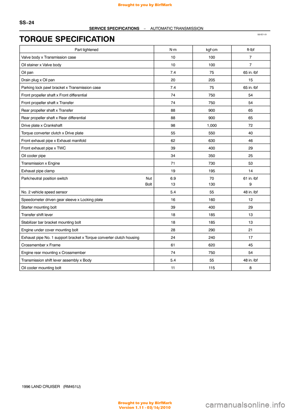
TORQUE SPECIFICATION
Part tightenedN·mkgf·cmft·lbf
Valve body x Transmission case101007
Oil stainer x Valve body101007
Oil pan7.47565 in.·lbf
Drain plug x Oil pan2020515
Parking lock pawl bracket x Transmission case7.47565 in.·lbf
Front propeller shaft x Front dif ferential7475054
Front propeller shaft x Transfer7475054
Rear propeller shaft x Transfer8890065
Rear propeller shaft x Rear dif ferential8890065
Drive plate x Crankshaft981,00072
Torque converter clutch x Drive plate5555040
Front exhaust pipe x Exhaust manifold6263046
Front exhaust pipe x TWC3940029
Oil cooler pipe3435025
Transmission x Engine7173053
Exhaust pipe clamp1919514
Park/neutral position switch Nut
Bolt6.9 1370
13061 in.·lbf 9
No. 2 vehicle speed sensor5.45548 in.·lbf
Speedometer driven gear sleeve x Locking plate1616012
Starter mounting bolt3940029
Transfer shift lever1818513
Stabilizer bar bracket mounting bolt1818513
Engine under cover mounting bolt2829021
Exhaust pipe No. 1 support bracket x Torque converter clutch housing2424017
Crossmember x Frame6162045
Engine rear mounting x Crossmember7475054
Transmission shift lever assembly x Body5.45548 in.·lbf
Oil cooler mounting bolt1111 58
Brought to you by BirfMark
Brought to you by BirfMark
Version 1.11 - 03/16/2010
Page 1326 of 1399
SS1E8−02
−
SERVICE SPECIFICATIONS TRANSFER
SS−25
148
Author�: Date�:
1996 LAND CRUISER (RM451U)
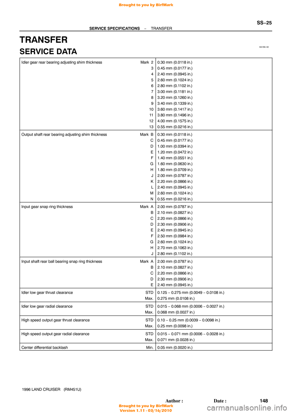
TRANSFER
SERVICE DATA
Idler gear rear bearing adjusting shim thickness Mark 2
3
4
5
6
7
8
9
10 11
12
130.30 mm (0.0118 in.)
0.45 mm (0.0177 in.)
2.40 mm (0.0945 in.)
2.60 mm (0.1024 in.)
2.80 mm (0.1102 in.)
3.00 mm (0.1181 in.)
3.20 mm (0.1260 in.)
3.40 mm (0.1339 in.)
3.60 mm (0.1417 in.)
3.80 mm (0.1496 in.)
4.00 mm (0.1575 in.)
0.55 mm (0.0216 in.)
Output shaft rear bearing adjusting shim thickness Mark B
C
DEF
G H J
K L
M N0.30 mm (0.0118 in.)
0.45 mm (0.0177 in.)
1.00 mm (0.0394 in.)
1.20 mm (0.0472 in.)
1.40 mm (0.0551 in.)
1.60 mm (0.0630 in.)
1.80 mm (0.0709 in.)
2.00 mm (0.0787 in.)
2.20 mm (0.0866 in.)
2.40 mm (0.0945 in.)
2.60 mm (0.1024 in.)
0.55 mm (0.0216 in.)
Input gear snap ring thickness Mark A
B
C
D E
F
G H J2.00 mm (0.0787 in.)
2.10 mm (0.0827 in.)
2.20 mm (0.0866 in.)
2.30 mm (0.0906 in.)
2.40 mm (0.0945 in.)
2.50 mm (0.0984 in.)
2.60 mm (0.1024 in.)
2.70 mm (0.1063 in.)
2.80 mm (0.1102 in.)
Input shaft rear ball bearing snap ring thickness Mark A
B
C
D E2.00 mm (0.0787 in.)
2.10 mm (0.0827 in.)
2.20 mm (0.0866 in.)
2.30 mm (0.0906 in.)
2.40 mm (0.0945 in.)
Idler low gear thrust clearance STD
Max.0.125 − 0.275 mm (0.0049 − 0.0108 in.)
0.275 mm (0.0108 in.)
Idler low gear radial clearance STD
Max.0.015 − 0.068 mm (0.0006 − 0.0027 in.)
0.068 mm (0.0027 in.)
High speed output gear thrust clearance STD
Max.0.10 − 0.25 mm (0.0039 − 0.0098 in.)
0.25 mm (0.0098 in.)
High speed output gear radial clearance STD
Max.0.015 − 0.071 mm (0.0006 − 0.0028 in.)
0.071 mm (0.0028 in.)
Center differential backlash Min.0.05 mm (0.0020 in.)
Brought to you by BirfMark
Brought to you by BirfMark
Version 1.11 - 03/16/2010