Page 1327 of 1399

Center differential side gear thrust washer thickness
1.70 mm (0.0669 in.)
1.85 mm (0.0728 in.)
2.00 mm (0.")
SS−26
−
SERVICE SPECIFICATIONS TRANSFER
149
Author�: Date�:
1996 LAND CRUISER (RM451U)
Center differential side gear thrust washer thickness
1.70 mm (0.0669 in.)
1.85 mm (0.0728 in.)
2.00 mm (0.0787 in.)
2.15 mm (0.0846 in.)
2.30 mm (0.0906 in.)
2.45 mm (0.0965 in.)
2.60 mm (0.1024 in.)
2.75 mm (0.1083 in.)
2.90 mm (0.1142 in.)
3.05 mm (0.1201 in.)
Front drive gear piece snap ring thickness
Mark A
B
C
D E
F
G H J
K
L2.00 mm (0.0787 in.)
2.10 mm (0.0827 in.)
2.20 mm (0.0866 in.)
2.30 mm (0.0906 in.)
2.40 mm (0.0945 in.)
2.50 mm (0.0984 in.)
2.60 mm (0.1024 in.)
2.70 mm (0.1063 in.)
2.80 mm (0.1102 in.)
1.80 mm (0.0709 in.)
1.90 mm (0.0748 in.)
Front extension housing ball bearing snap ring thickness Mark A
B1.7 mm (0.0669 in.)
1.8 mm (0.0709 in.)
Front output shaft hub snap ring thickness Mark A
B
C
D E1.8 mm (0.0709 in.)
1.9 mm (0.0748 in.)
2.0 mm (0.0787 in.)
2.1 mm (0.0827 in.)
2.2 mm (0.0866 in.)
Oil pump driven rotor body clearance STD
Max.0.08 − 0.17 mm (0.0031 − 0.0067 in.)
0.17 mm (0.0067 in.)
Oil pump driven rotor body tip clearance STD
Max.0.05 − 0.15 mm (0.0020 − 0.0059 in.)
0.15 mm (0.0059 in.)
Oil pump side clearance STD
Max.0.03 − 0.10 mm (0.0012 − 0.0039 in.)
0.10 mm (0.0039 in.)
Rear extension housing ball bearing snap ring thickness Mark A
B1.7 mm (0.0669 in.)
1.8 mm (0.0709 in.)
Rear output shaft ball bearing snap ring thickness Mark 1
2
3
41.95 mm (0.0768 in.)
2.05 mm (0.0807 in.)
2.15 mm (0.0847 in.)
2.25 mm (0.0886 in.)
Motor actuator
Terminal 2 − Terminal 3 STD resistance
Terminal 2 or 3 − Body ground STD resistance
0.3 − 100 Ω
More than 0.5 MΩ
Brought to you by BirfMark
Brought to you by BirfMark
Version 1.11 - 03/16/2010
Page 1328 of 1399
SS1E9−02
−
SERVICE SPECIFICATIONS TRANSFER
SS−27
1996 LAND CRUISER (RM451U)
TORQUE SPECIFICATION
Part tightenedN·mkgf·cmft·lbf
Oil pump plate and separator x Rear extension housing4.95043 in.·lbf
Oil pump cover x Rear extension housing4.95043 in.·lbf
Lever lock pin121209
Oil strainer x Rear case4.95043 in.·lbf
Oil receiver x Front case121209
Case cover x Rear case3738027
Rear extension housing x Rear case3738027
Front extension housing x Front case3738027
Center differential lock Indicator switch3738014
L4 position switch3738027
Neutral position switch3738027
Screw plug x Front case1919014
Screw plug x Rear extension housing2930022
Motor actuator x Front case1818513
Differential front case x Differential rear case
Temporarily tighten98
881,00090072
65
Front case x Rear case3738027
Rear case x Retainer3940028
Dynamic damper x Rear extension housing3738027
Brought to you by BirfMark
Brought to you by BirfMark
Version 1.11 - 03/16/2010
Page 1330 of 1399
SS1EB−01
−
SERVICE SPECIFICATIONS PROPELLER SHAFT
SS−29
1996 LAND CRUISER (RM451U)
TORQUE SPECIFICATION
Part tightenedN·mkgf·cmft·lbf
Front propeller shaft x Front dif ferential7475054
Front propeller shaft x Transfer7475054
Rear propeller shaft x Rear differential8890065
Rear propeller shaft x Transfer8890065
Brought to you by BirfMark
Brought to you by BirfMark
Version 1.11 - 03/16/2010
Page 1363 of 1399
TR0AX−01
−
TRANSFER TRANSFER SYSTEM
TR−1
811
Author�: Date�:
1996 LAND CRUISER (RM451U)
TRANSFER SYSTEM
PRECAUTION
�When working with FIPG material, you must observe the following.
�Using a razor blade and gasket scraper, remove all the old FIPG material from the gasket sur-
faces.
�Thoroughly clean all components to remove all the loose material.
�Clean both sealing surfaces with a non −residue solvent.
�Apply FIPG in an approx. 1 mm (0.04 in.) wide bead along the sealing s\
urface.
�Parts must be assembled within 10 minutes of application. Otherwise, the FIPG\
material must
be removed and reapplied.
Brought to you by BirfMark
Brought to you by BirfMark
Version 1.11 - 03/16/2010
Page 1364 of 1399
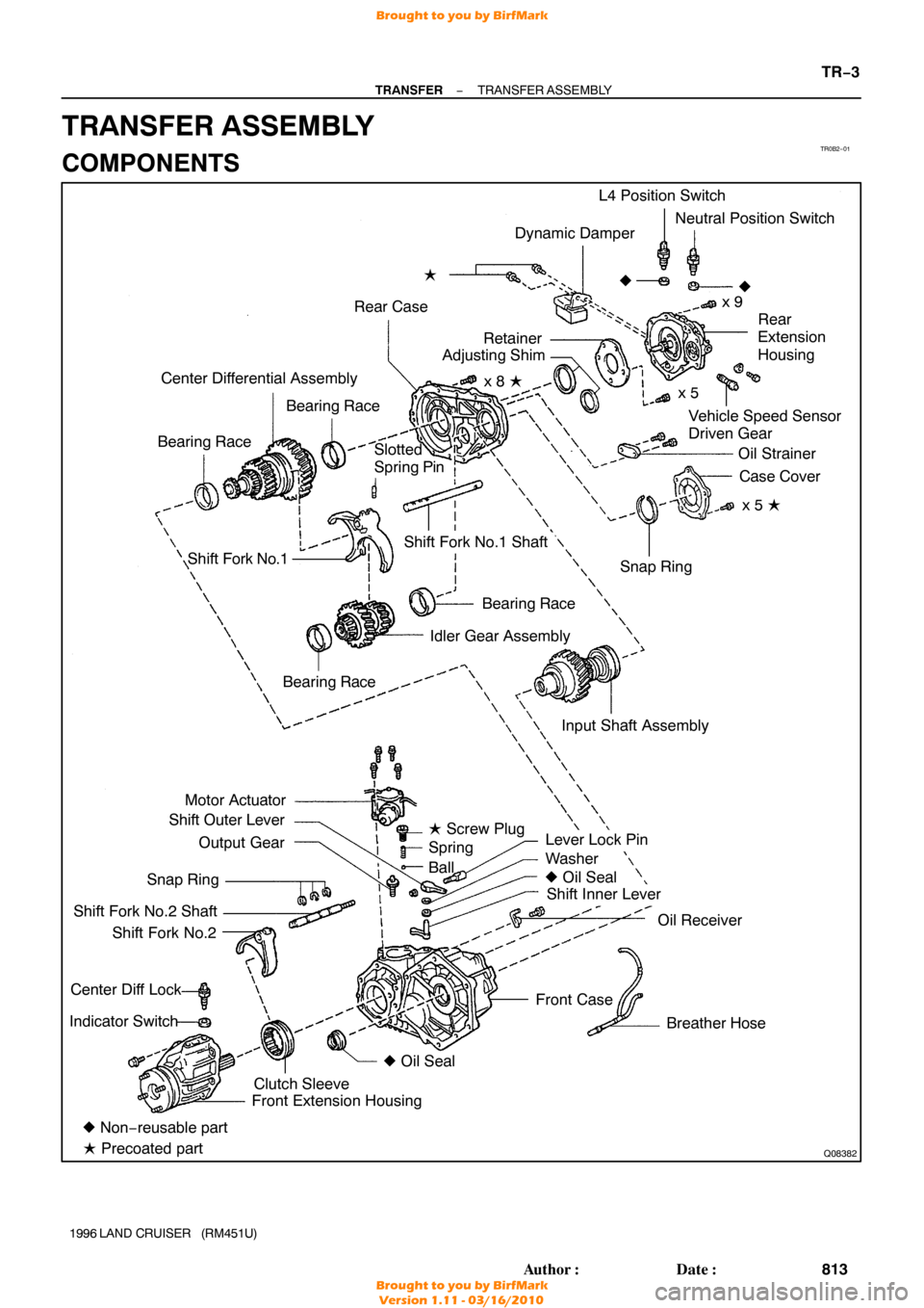
TR0B2−01
Q08382
Dynamic Damper
Rear Case �
Vehicle Speed Sensor
Driven Gear
Center Differential Assembly
Bearing Race
Bearing Race L4 Position Switch
Neutral Position Switch
x 9
�
Rear
Extension
Housing
Oil Strainer Case Cover
x 5 �
Shift Fork No.1
Bearing Race
Idler Gear Assembly
Motor Actuator
Shift Outer Lever
Output Gear
Snap Ring
Shift Fork No.2 Shaft Shift Fork No.2
Center Diff Lock
Indicator Switch
Lever Lock Pin
Washer
� Oil Seal
Shift Inner Lever
Oil Receiver
Breather Hose
Front Case Snap Ring
Shift Fork No.1 Shaft
� Non− reusable part
� Precoated part Front Extension Housing
Clutch Sleeve �
Oil Seal
Bearing Race
�
Slotted
Spring Pin
Input Shaft Assemblyx 5
x 8 �
Retainer
Adjusting Shim
� Screw Plug
Spring
Ball
−
TRANSFER TRANSFER ASSEMBLY
TR−3
813
Author�: Date�:
1996 LAND CRUISER (RM451U)
TRANSFER ASSEMBLY
COMPONENTS
Brought to you by BirfMark
Brought to you by BirfMark
Version 1.11 - 03/16/2010
Page 1365 of 1399

DISASSEMBLY
1. REMOVE BREATHER HOSE
2. REMOVE DYNAMIC DAMPER
Remove the 2 bolts and dynamic damper.
HIN")
TR0CM−01
Q07105
Q07124
FIPG
TR−4
−
TRANSFER TRANSFER ASSEMBLY
1996 LAND CRUISER (RM451U)
DISASSEMBLY
1. REMOVE BREATHER HOSE
2. REMOVE DYNAMIC DAMPER
Remove the 2 bolts and dynamic damper.
HINT:
At the time of reassembly, apply adhesive to the bolt threads. Adhesive: Part No.08833 −00070, THREE BOND 1324
or equivalent
Torque: 37 N·m (380 kgf·cm, 27 ft·lbf)
3. REMOVE MOTOR ACTUATOR
Remove the 4 bolts and motor actuator.
HINT:
At the time of reassembly, please refer to the following items.
�Set the motor actuator in differential lock condition.
�Apply FIPG to the front case.
FIPG: Part No. 08826−00090, THREE BOND 1281 or
equivalent
Torque: 18 N·m (185 kgf·cm, 13 ft·lbf)
4. REMOVE OUTPUT GEAR FROM FRONT CASE
HINT:
At the timie of reassembly apply gear oil to the output gear.
NOTICE:
At the time of reassembly, do not turn the output gear.
5. REMOVE SCREW PLUG, SPRING AND BALL
(a) Using a torx socket wrench (T40), remove the screw plug.
HINT:
At the time of reassembly, apply liquid sealer to the screw plug. Sealant: Part No.08833−00080, THREE BOND 1344,
LOCTITE 242 or equivalent
Torque:19 N·m (190 kgf·cm, 14 ft·lbf)
(b) Using a magnetic finger, remove the spring and ball.
Brought to you by BirfMark
Brought to you by BirfMark
Version 1.11 - 03/16/2010
Page 1366 of 1399

6. REMOVE TRANSFER INDICATOR SWITCH
Remove the Center Diff Lock indicator switch, L4 position")
Q04610
Q00541
Front
Q02950
Q07125
FIPG
−
TRANSFER TRANSFER ASSEMBLY
TR−5
1996 LAND CRUISER (RM451U)
6. REMOVE TRANSFER INDICATOR SWITCH
Remove the Center Diff Lock indicator switch, L4 position
switch, Neutral position switch and 3 gaskets.
Torque: 37 N·m (380 kgf·cm, 27 ft·lbf)
7. REMOVE FRONT EXTENSION HOUSING
Remove the 6 bolts and front extension housing.
HINT:
If necessary, tap the front extension housing with a plastic ham-
mer.
HINT:
At the time of reassembly, please refer to the following items.
�Set the clutch sleeve in differential lock condition.
�Apply FIPG to the front case.
FIPG: Part No. 08826−00090, THREE BOND 1281 or
equivalent
Torque: 37 N·m (380 kgf·cm, 27 ft·lbf)
8. REMOVE CLUTCH SLEEVE, SHIFT FORK NO.2 SHAFT AND SHIFT FORK NO.2
HINT:
At the time of reassebly, make sure to install the clutch sleeve
in the correct direction.
9. SEPARATE SHIFT FORK NO.2 SHAFT AND SHIFT FORK NO.2
(a) Using 2 screwdrivers and a hammer, tap out the 3 snap rings from the shift fork No.2 shaft.
(b) Separate the shift fork No.2 shaft and shift fork No.2.
10. REMOVE REAR EXTENSION HOUSING
Remove the 9 bolts and rear extension housing.
HINT:
If necessary, tap the rear extension housing with a plastic ham-
mer.
HINT:
At the time of reassembly, apply FIPG to the rear case. FIPG: Part No. 08826−00090, THREE BOND 1281 or
equivalent
Torque: 37 N·m (380 kgf·cm, 27 ft·lbf)
Brought to you by BirfMark
Brought to you by BirfMark
Version 1.11 - 03/16/2010
Page 1367 of 1399

11. REMOVE RETAINER FROM REAR CASE
Remove the 5 bolts and retainer.
Torque: 39 N·m (400 kgf·cm, 28 ft·lbf)
12.")
Z18976
B
Z18977
C
TR−6
−
TRANSFER TRANSFER ASSEMBLY
1996 LAND CRUISER (RM451U)
11. REMOVE RETAINER FROM REAR CASE
Remove the 5 bolts and retainer.
Torque: 39 N·m (400 kgf·cm, 28 ft·lbf)
12. REMOVE ADJUSTING SHIM
HINT:
At the time of assembly, select adjusting shims for the idler gear
rear taper roller bearing.
(a) Using vernier calipers, measure dimension A.
(b) Lightly hold down the bearing outer race in the thrust direction to eliminate any looseness before making the
measurement.
(c) Using a steel straight edge and feeler gauge, measure the clearance of dimension B.
(d) Calculate the required thickness of the adjusting shim. Thickness:
Dimension A + Dimension B + (0.022 − 0.049 mm,
0.0009 − 0.0019 in.)
(e) From the following table, select a shim so that its thick- ness is within the range of the calculation.
MarkThickness mm (in.)MarkThickness mm (in.)
20.30 (0.0118)83.20 (0.1260)
30.45 (0.0177)93.40 (0.1339)
42.40 (0.0945)103.60 (0.1417)
52.60 (0.1024)113.80 (0.1496)
62.80 (0.1 102)124.00 (0.1575)
73.00 (0.1181)130.55 (0.0216)
HINT:
At the time of reassembly, select adjusting shims for the output
shaft taper roller bearing.
(f) Using a steel straight edge and feeler gauge, measure
the clearance of dimension C.
(g) Lightly hold down the bearing outer race in the thrust direction to eliminate any looseness before making the
measurement.
(h) Calculate the required thickness of the adjusting shim.
Brought to you by BirfMark
Brought to you by BirfMark
Version 1.11 - 03/16/2010

TORQUE SPECIFICATION
Part tightenedN·mkgf·cmft·lbf
Oil pump plate and separator x Rear extension housing4.95043 i")

TORQUE SPECIFICATION
Part tightenedN·mkgf·cmft·lbf
Front propeller shaft x Front dif ferential7475054
Fron")