Page 421 of 1399
CH06N−03
−
CHARGING GENERATOR
CH−19
1996 LAND CRUISER (RM451U)
INSTALLATION
1. INSTALL GENERATOR
(a) Mount generator on the generator bracket with the pivot
bolt. Do not tighten the bolt yet.
(b) Install the drive belt adjusting bar with the bolt and nut. Torque: 21 N·m (210 kgf·cm, 15 ft·lbf)
(c) Temporarily install the lock bolt.
(d) Connect the generator connector.
(e) Connect the generator wire with the nut and rubber cap.
(f) Connect the generator wire clamp to the generator.
2. INSTALL DRIVE BELTS
(a) Install the drive belts.
(b) Adjust the drive belt with the adjusting bolt (See page
CH−2 ).
(c) Tighten the pivot and adjusting lock bolts. Torque:
Pivot bolt: 59 N·m (600 kgf·cm, 43 ft·lbf)
Lock bolt: 21 N·m (210 kgf·cm, 15 ft·lbf)
3. CONNECT POWER STEERING (PS) RESERVOIR TANK
4. INSTALL BATTERY TRAY AND BATTERY
5. PERFORM ON−VEHICLE INSPECTION (See page CH−2 )
Brought to you by BirfMark
Brought to you by BirfMark
Version 1.11 - 03/16/2010
Page 425 of 1399
CO112−01
CO−4
−
COOLING WATER PUMP
1996 LAND CRUISER (RM451U)
REMOVAL
1. DRAIN ENGINE COOLANT
2. DISCONNECT NO.3 WATER BYPASS HOSE
3. DISCONNECT RADIATOR INLET HOSE
4. REMOVE DRIVE BELTS, FAN WITH FLUID COU- PLING, WATER PUMP PULLEY AND FAN SHROUD
(a) Stretch the belts and loosen the water pump pulley mounting nuts.
(b) Loosen the lock, pivot and adjusting bolts of the genera- tor, and remove the drive belts.
(c) Disconnect the oil cooler hose from the clamp on the fan shroud.
(d) Remove the 2 bolts holding the fan shroud to the radiator.
(e) Remove the 4 water pump pulley mounting nuts.
(f) Pull out the fan with fluid coupling, water pump pulley and
fan shroud.
(g) Remove the fan from the fluid coupling.
5. REMOVE WATER PUMP
Remove the 4 bolts, 2 nuts, water pump and gasket.
Brought to you by BirfMark
Brought to you by BirfMark
Version 1.11 - 03/16/2010
Page 427 of 1399

CO114−02
CO−6
−
COOLING WATER PUMP
1996 LAND CRUISER (RM451U)
INSTALLATION
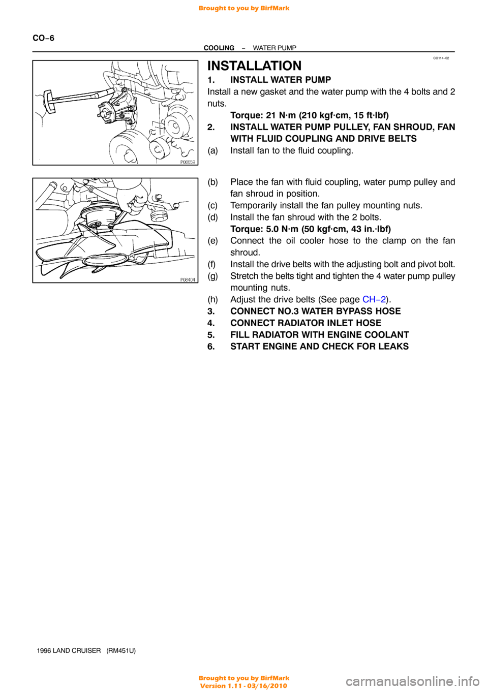
1. INSTALL WATER PUMP
Install a new gasket and the water pump with the 4 bolts and 2
nuts. Torque: 21 N·m (210 kgf·cm, 15 ft·lbf)
2. INSTALL WATER PUMP PULLEY, FAN SHROUD, FAN WITH FLUID COUPLING AND DRIVE BELTS
(a) Install fan to the fluid coupling.
(b) Place the fan with fluid coupling, water pump pulley and fan shroud in position.
(c) Temporarily install the fan pulley mounting nuts.
(d) Install the fan shroud with the 2 bolts. Torque: 5.0 N·m (50 kgf·cm, 43 in.·lbf)
(e) Connect the oil cooler hose to the clamp on the fan
shroud.
(f) Install the drive belts with the adjusting bolt and pivot bolt.
(g) Stretch the belts tight and tighten the 4 water pump pulley mounting nuts.
(h) Adjust the drive belts (See page CH−2 ).
3. CONNECT NO.3 WATER BYPASS HOSE
4. CONNECT RADIATOR INLET HOSE
5. FILL RADIATOR WITH ENGINE COOLANT
6. START ENGINE AND CHECK FOR LEAKS
Brought to you by BirfMark
Brought to you by BirfMark
Version 1.11 - 03/16/2010
Page 435 of 1399

CO117−02
CO−14
−
COOLING RADIATOR
1996 LAND CRUISER (RM451U)
REMOVAL
1. DRAIN ENGINE COOLANT
2. REMOVE BATTERY AND BATTERY TRAY
(a) Disconnect the battery cables.
(b) Remove the nuts, hold −down clamp and battery.
(c) Remove the bolt and disconnect the ground strap.
(d) Remove the 5 bolts and battery tray.
3. REMOVE RADIATOR GRILLE
Remove the 5 screws, clip and radiator grille.
4. DISCONNECT NO.3 WATER BYPASS HOSE
5. DISCONNECT RADIATOR INLET HOSE
6. DISCONNECT RADIATOR RESERVOIR HOSE
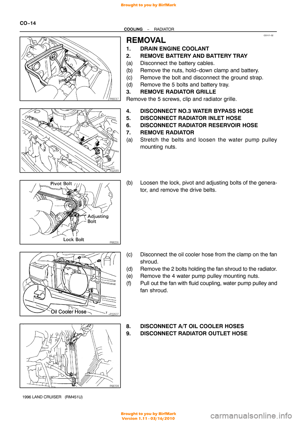
7. REMOVE RADIATOR
(a) Stretch the belts and loosen the water pump pulley mounting nuts.
(b) Loosen the lock, pivot and adjusting bolts of the genera- tor, and remove the drive belts.
(c) Disconnect the oil cooler hose from the clamp on the fan shroud.
(d) Remove the 2 bolts holding the fan shroud to the radiator.
(e) Remove the 4 water pump pulley mounting nuts.
(f) Pull out the fan with fluid coupling, water pump pulley and
fan shroud.
8. DISCONNECT A/T OIL COOLER HOSES
9. DISCONNECT RADIATOR OUTLET HOSE
Brought to you by BirfMark
Brought to you by BirfMark
Version 1.11 - 03/16/2010
Page 437 of 1399

CO118−01
CO−16
−
COOLING RADIATOR
1996 LAND CRUISER (RM451U)
INSTALLATION
1. INSTALL RADIATOR
(a) Install the 2 radiator brackets with the 4 nuts. Torque: 12 N·m (120 kgf·cm, 9 ft·lbf)
(b) Install the radiator with the 2 bolts and 2 nuts. Torque:
Bolt: 18 N·m (185 kgf·cm, 13 ft·lbf)
Nut: 12 N·m (120 kgf·cm, 9 ft·lbf)
2. CONNECT A/T OIL COOLER HOSES
3. CONNECT RADIATOR OUTLET HOSE
4. INSTALL WATER PUMP PULLEY, FAN SHROUD, FAN WITH FLUID COUPLING AND DRIVE BELTS
(a) Place the fan with fluid coupling, water pump pulley and fan shroud in position.
(b) Temporarily install the fan pulley mounting nuts.
(c) Install the fan shroud with the 2 bolts. Torque: 5.0 N·m (50 kgf·cm, 43 in.·lbf)
(d) Connect the oil cooler hose to the clamp on the fan
shroud.
(e) Install the drive belts with the adjusting bolt and pivot bolt.
(f) Stretch the belts tight and tighten the 4 water pump pulley mounting nuts.
(g) Adjust the drive belts (See page CH−2 ).
5. CONNECT RADIATOR RESERVOIR HOSE
6. CONNECT RADIATOR INLET HOSE
7. CONNECT NO.3 WATER BYPASS HOSE
8. INSTALL RADIATOR GRILLE
Install the radiator grille with the 5 screws and clip.
9. INSTALL BATTERY AND BATTERY TRAY
(a) Install the battery tray with the 5 bolts.
(b) Connect the ground strap with the bolt.
(c) Install the battery with the hold−down clamp and nuts.
(d) Connect the battery cables.
10. FILL RADIATOR WITH ENGINE COOLANT
11. START ENGINE AND CHECK FOR LEAKS
12. CHECK AUTOMATIC TRANSMISSION FLUID LEVEL
Brought to you by BirfMark
Brought to you by BirfMark
Version 1.11 - 03/16/2010
Page 798 of 1399
EM1E9−01
−
ENGINE MECHANICAL TIMING CHAIN
EM−13
1996 LAND CRUISER (RM451U)
REMOVAL
1. DRAIN ENGINE OIL
2. DRAIN ENGINE COOLANT
3. REMOVE ENGINE UNDER COVER
4. REMOVE RADIATOR (See page CO−14 )
5. DISCONNECT A/C COMPRESSOR AND BRACKET
(a) Loosen the idler pulley nut and adjusting bolt, and remove
the drive belt.
(b) Remove the 4 mounting bolts, and disconnect the com- pressor from the bracket.
HINT:
Put aside the compressor, and suspend it.
(c) Remove the 5 bolts and A/C compressor bracket.
6. REMOVE RADIATOR PIPE
(a) Disconnect the No. 2 radiator hose from the water inlet.
(b) Remove the 2 nuts and radiator pipe.
7. REMOVE WATER PUMP
Remove the 4 bolts, 2 nuts, water pump and gasket.
8. REMOVE CYLINDER HEAD (See page EM−28 )
Brought to you by BirfMark
Brought to you by BirfMark
Version 1.11 - 03/16/2010
Page 800 of 1399

−
ENGINE MECHANICAL TIMING CHAIN
EM−15
1996 LAND CRUISER (RM451U)
15. CHECK THRUST CLEARANCE OF OIL PUMP DRIVE
SHAFT GEAR
Using a dial indicator with lever type attachment, measure the
thrust clearance.
Standard thrust clearance:
0.040 − 0.160 mm (0.0016 − 0.0063 in.)
Maximum thrust clearance: 0.30 mm (0.0118 in.)
If the thrust clearance is greater than maximum, replace the oil
pump drive shaft gear and/or timing chain cover.
16. REMOVE DRIVE BELT IDLER PULLEY
Remove the bolt and idler pulley.
17. REMOVE TIMING CHAIN COVER
(a) Remove the 9 mounting bolts, 2 mounting nuts and drive belt adjusting bar.
(b) Remove the oil pump by prying the portions between the cylinder block and oil pump with a screwdriver.
NOTICE:
Be careful not to damage the contact surfaces of the cylin-
der block and oil pump.
(c) Remove the O−rings from the oil pump.
(d) Remove the gasket from the oil pump.
18. REMOVE TIMING CHAIN AND CAMSHAFT TIMING GEAR
Brought to you by BirfMark
Brought to you by BirfMark
Version 1.11 - 03/16/2010
Page 807 of 1399

EM−22
−
ENGINE MECHANICAL TIMING CHAIN
1996 LAND CRUISER (RM451U)
(d) Engage the gear of the oil pump drive rotor with the gear
of the oil pump drive gear, and install the oil pump.
(e) Install the oil pump and drive belt adjusting bar with the 9 bolts and 2 nuts.
Torque: 21 N·m (210 kgf·cm, 15 ft·lbf)
HINT:
Each bolt length is indicated in the illustration.
Bolt A: 30 mm (1.18 in.)
Bolt B: 50 mm (1.97 in.)
Bolt C: 60 mm (2.38 in.)
(f) Remove the cord from the chain.
10. INSTALL DRIVE BELT IDLER PULLEY
Install the pulley with the bolt. Torque: 43 N·m (440 kgf·cm, 32 ft·lbf)
11. INSTALL CRANKSHAFT PULLEY
(a) Align the pulley set key with the key groove of the pulley, and slide on the pulley.
(b) Using SST, install and torque the pulley bolt.
SST 09213−58012, 09330 −00021
Torque: 412 N·m (4,200 kgf·cm, 304 ft·lbf)
12. INSTALL NO. 1 OIL PAN (See page LU−12)
13. INSTALL NO. 2 OIL PAN (See page LU−12)
14. INSTALL BOLTS HOLDING NO. 1 OIL PAN TO TRANS-
MISSION HOUSING
Install the 6 bolts. Torque: 72 N·m (730 kgf·cm, 53 ft·lbf)
Brought to you by BirfMark
Brought to you by BirfMark
Version 1.11 - 03/16/2010