Page 1270 of 1399
SR16E−03
−
STEERING TILT STEERING COLUMN
SR−19
1996 LAND CRUISER (RM451U)
INSTALLATION
1. INSTALL STEERING COLUMN ASSEMBLY
(a) Torque the 2 column assembly set nuts and 2 set bolts.
Torque:25 N·m (250 kgf·cm, 18 ft·lbf)
(b) Connect the 3 connectors.
2. INSTALL SLIDING YOKE SUB −ASSEMBLY
Temporarily tighten the bolt A.
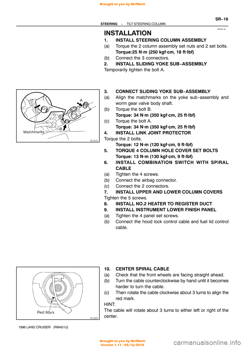
3. CONNECT SLIDING YOKE SUB−ASSEMBLY
(a) Align the matchmarks on the yoke sub−assembly and
worm gear valve body shaft.
(b) Torque the bolt B. Torque: 34 N·m (350 kgf·cm, 25 ft·lbf)
(c) Torque the bolt A.
Torque: 34 N·m (350 kgf·cm, 25 ft·lbf)
4. INSTALL LINK JOINT PROTECTOR
Torque the 2 bolts. Torque: 12 N·m (120 kgf·cm, 9 ft·lbf)
5. TORQUE 4 COLUMN HOLE COVER SET BOLTS Torque: 13 N·m (130 kgf·cm, 9 ft·lbf)
6. INSTALL COMBINATION SWITCH WITH SPIRAL CABLE
(a) Tighten the 4 screws.
(b) Connect the airbag connector.
(c) Connect the 2 connectors.
7. INSTALL UPPER AND LOWER COLUMN COVERS
Tighten the 5 screws.
8. INSTALL NO.2 HEATER TO REGISTER DUCT
9. INSTALL INSTRUMENT LOWER FINISH PANEL
(a) Tighten the 4 panel set screws.
(b) Connect the hood lock control cable and fuel lid control cable.
10. CENTER SPIRAL CABLE
(a) Check that the front wheels are facing straight ahead.
(b) Turn the cable counterclockwise by hand until it becomes harder to turn the cable.
(c) Then rotate the cable clockwise about 3 turns to align the
red mark.
HINT:
The cable will rotate about 3 turns to either left or right of the
center.
Brought to you by BirfMark
Brought to you by BirfMark
Version 1.11 - 03/16/2010
Page 1296 of 1399
SR16Q−01
SR2922
Alignment Marks
−
STEERING POWER STEERING GEAR
SR−43
1996 LAND CRUISER (RM451U)
INSTALLATION
1. INSTALL PS GEAR ASSEMBLY
Torque the 4 installation bolts and nuts.
Torque: 142 N·m (1,450 kgf·cm, 105 ft·lbf)
2. CONNECT SLIDING YOKE SUB−ASSEMBLY (See page SR−19 )
3. CONNECT PRESSURE FEED AND RETURN TUBES
Using SST, connect the pressure feed and return tubes. SST 09631−22020
Torque: 36 N·m (365 kgf·cm, 26 ft·lbf)
HINT:
�Use a torque wrench with a fulcrum length of 300 mm
(11.81 in.).
�This torque value is effective in case that SST is parallel
to a torque wrench.
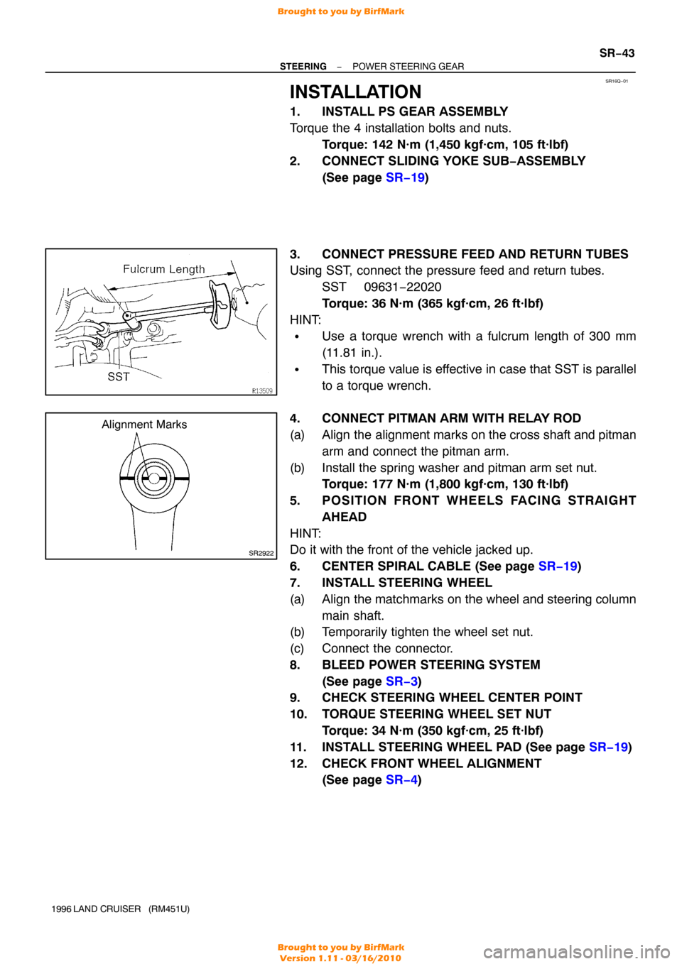
4. CONNECT PITMAN ARM WITH RELAY ROD
(a) Align the alignment marks on the cross shaft and pitman arm and connect the pitman arm.
(b) Install the spring washer and pitman arm set nut. Torque: 177 N·m (1,800 kgf·cm, 130 ft·lbf)
5. POSITION FRONT WHEELS FACING STRAIGHT AHEAD
HINT:
Do it with the front of the vehicle jacked up.
6. CENTER SPIRAL CABLE (See page SR−19 )
7. INSTALL STEERING WHEEL
(a) Align the matchmarks on the wheel and steering column main shaft.
(b) Temporarily tighten the wheel set nut.
(c) Connect the connector.
8. BLEED POWER STEERING SYSTEM
(See page SR−3 )
9. CHECK STEERING WHEEL CENTER POINT
10. TORQUE STEERING WHEEL SET NUT
Torque: 34 N·m (350 kgf·cm, 25 ft·lbf)
11. INSTALL STEERING WHEEL PAD (See page SR−19)
12. CHECK FRONT WHEEL ALIGNMENT (See page SR−4 )
Brought to you by BirfMark
Brought to you by BirfMark
Version 1.11 - 03/16/2010
Page 1301 of 1399
SR2922
Alignment Marks
SR−48
−
STEERING STEERING LINKAGE
1996 LAND CRUISER (RM451U)
6. INSTALL PITMAN ARM
(a) Align the alignment marks on the pitman arm and the
cross shaft, and install the spring washer and set nut.
Torque: 177 N·m (1,800 kgf·cm, 130 ft·lbf)
(b) Connect the pitman arm to the relay rod assembly.
(c) Torque the nut. Torque: 91 N·m (925 kgf·cm, 67 ft·lbf)
(d) Install a new cotter pin.
7. INSTALL ENGINE UNDER COVER
Tighten the 4 bolts.
8. CHECK FRONT WHEEL ALIGNMENT (See page SA−4 )
Brought to you by BirfMark
Brought to you by BirfMark
Version 1.11 - 03/16/2010
Page 1334 of 1399
SS1ED−02
−
SERVICE SPECIFICATIONS SUSPENSION AND AXLE
SS−33
1996 LAND CRUISER (RM451U)
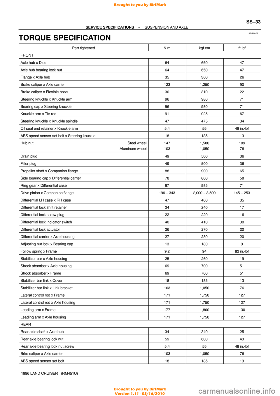
TORQUE SPECIFICATION
Part tightenedN·mkgf·cmft·lbf
FRONT
Axle hub x Disc6465047
Axle hub bearing lock nut6465047
Flange x Axle hub3536026
Brake caliper x Axle carrier1231,25090
Brake caliper x Flexible hose3031022
Steering knuckle x Knuckle arm9698071
Bearing cap x Steering knuckle9698071
Knuckle arm x Tie rod9192567
Steering knuckle x Knuckle spindle4747534
Oil seal end retainer x Knuckle arm5.45548 in.·lbf
ABS speed sensor set bolt x Steering knuckle1818513
Hub nut Steel wheel
Aluminum wheel147
1031,500
1,050109 76
Drain plug4950036
Filler plug4950036
Propeller shaft x Companion flange8890065
Side bearing cap x Differential carrier7880058
Ring gear x Differential case9798571
Drive pinion x Companion flange196 − 3432,000 − 3,500145 − 253
Differential LH case x RH case4748035
Differential lock shift retainer2424017
Differential lock screw plug2222016
Differential lock indicator switch4041030
Differential lock actuator2627020
Differential carrier x Axle housing2728020
Adjusting nut lock x Bearing cap131309
Follow spring x Frame9.29482 in.·lbf
Stabilizer bar x Axle housing2526019
Shock absorber x Axle housing6970051
Shock absorber x Frame6970051
Stabilizer bar link x Cover1818513
Stabilizer bar link x Link bracket1031,05076
Lateral control rod x Frame1711,750127
Lateral control rod x Axle housing1711,750127
Leading arm x Frame1771,800130
Leading arm x Axle housing1711,750127
REAR
Rear axle shaft x Axle hub3434025
Rear axle bearing lock nut5960043
Rear axle bearing lock nut screw5.45548 in.·lbf
Brke caliper x Axle carrier1031,05076
ABS speed sensor set bolt1818513
Brought to you by BirfMark
Brought to you by BirfMark
Version 1.11 - 03/16/2010
Page 1335 of 1399
SS−34
−
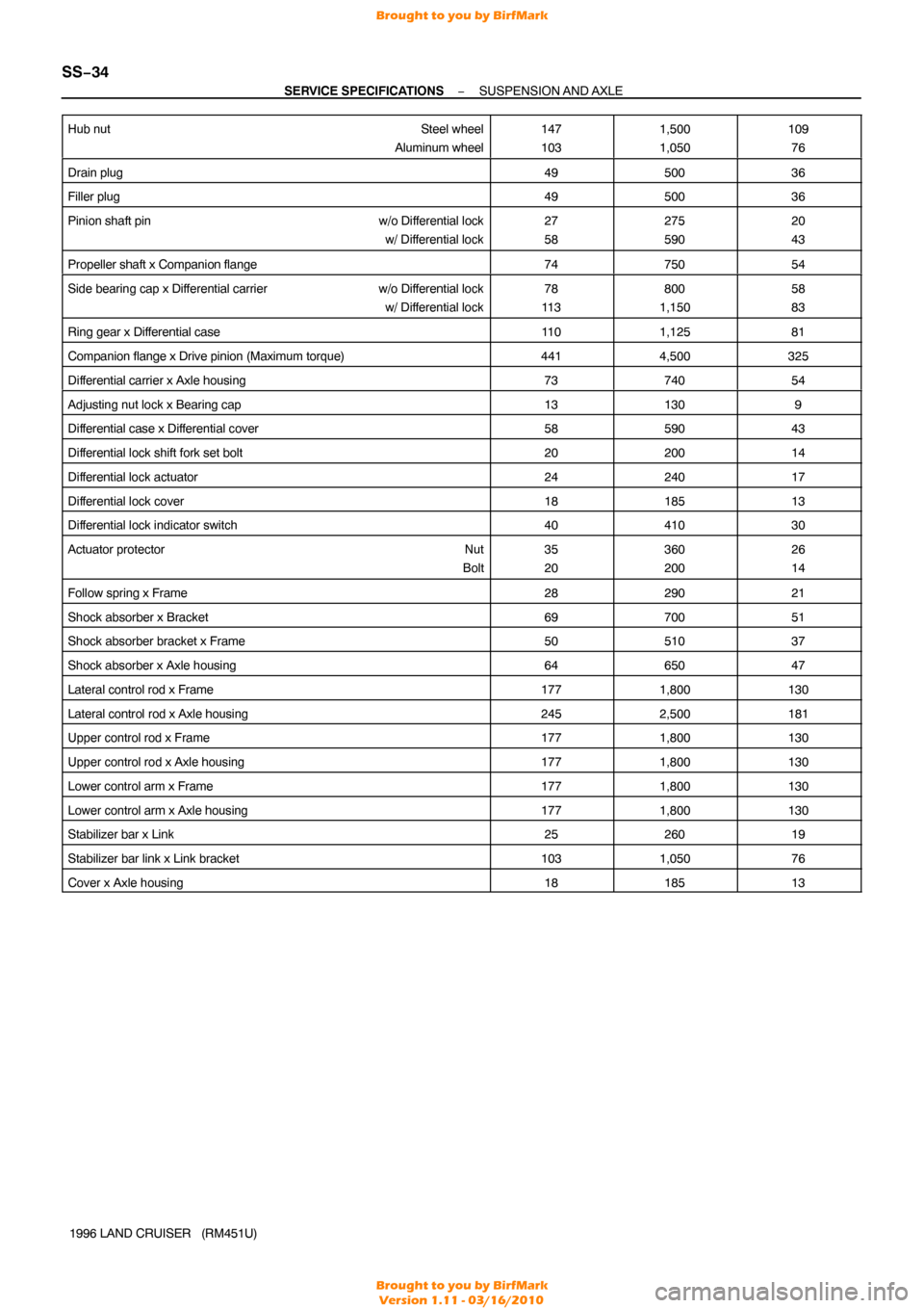
SERVICE SPECIFICATIONS SUSPENSION AND AXLE
1996 LAND CRUISER (RM451U)
Hub nut
Steel wheel
Aluminum wheel
147
1031,500
1,050109 76
Drain plug4950036
Filler plug4950036
Pinion shaft pin w/o Differential lock
w/ Differential lock27
58275
59020
43
Propeller shaft x Companion flange7475054
Side bearing cap x Differential carrier w/o Differential lock
w/ Differential lock78
11 3800
1,15058
83
Ring gear x Differential case11 01,12581
Companion flange x Drive pinion (Maximum torque)4414,500325
Differential carrier x Axle housing7374054
Adjusting nut lock x Bearing cap131309
Differential case x Differential cover5859043
Differential lock shift fork set bolt2020014
Differential lock actuator2424017
Differential lock cover1818513
Differential lock indicator switch4041030
Actuator protector Nut
Bolt35
20360
20026
14
Follow spring x Frame2829021
Shock absorber x Bracket6970051
Shock absorber bracket x Frame5051037
Shock absorber x Axle housing6465047
Lateral control rod x Frame1771,800130
Lateral control rod x Axle housing2452,500181
Upper control rod x Frame1771,800130
Upper control rod x Axle housing1771,800130
Lower control arm x Frame1771,800130
Lower control arm x Axle housing1771,800130
Stabilizer bar x Link2526019
Stabilizer bar link x Link bracket1031,05076
Cover x Axle housing1818513
Brought to you by BirfMark
Brought to you by BirfMark
Version 1.11 - 03/16/2010
Page 1339 of 1399
SS1EH−02
SS−38
−
SERVICE SPECIFICATIONS STEERING
1996 LAND CRUISER (RM451U)
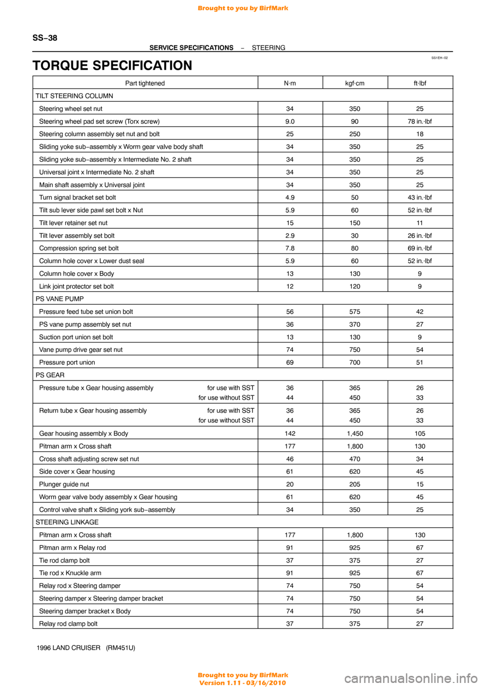
TORQUE SPECIFICATION
Part tightenedN·mkgf·cmft·lbf
TILT STEERING COLUMN
Steering wheel set nut3435025
Steering wheel pad set screw (T orx screw)9.09078 in.·lbf
Steering column assembly set nut and bolt2525018
Sliding yoke sub−assembly x Worm gear valve body shaft3435025
Sliding yoke sub −assembly x Intermediate No. 2 shaft3435025
Universal joint x Intermediate No. 2 shaft3435025
Main shaft assembly x Universal joint3435025
Turn signal bracket set bolt4.95043 in.·lbf
Tilt sub lever side pawl set bolt x Nut5.96052 in.·lbf
Tilt lever retainer set nut1515011
Tilt lever assembly set bolt2.93026 in.·lbf
Compression spring set bolt7.88069 in.·lbf
Column hole cover x Lower dust seal5.96052 in.·lbf
Column hole cover x Body131309
Link joint protector set bolt121209
PS VANE PUMP
Pressure feed tube set union bolt5657542
PS vane pump assembly set nut3637027
Suction port union set bolt131309
Vane pump drive gear set nut7475054
Pressure port union6970051
PS GEAR
Pressure tube x Gear housing assembly for use with SST
for use without SST36
44365
45026
33
Return tube x Gear housing assembly for use with SST
for use without SST36
44365
45026
33
Gear housing assembly x Body1421,450105
Pitman arm x Cross shaft1771,800130
Cross shaft adjusting screw set nut4647034
Side cover x Gear housing6162045
Plunger guide nut2020515
Worm gear valve body assembly x Gear housing6162045
Control valve shaft x Sliding york sub −assembly3435025
STEERING LINKAGE
Pitman arm x Cross shaft1771,800130
Pitman arm x Relay rod9192567
Tie rod clamp bolt3737527
Tie rod x Knuckle arm9192567
Relay rod x Steering damper7475054
Steering damper x Steering damper bracket7475054
Steering damper bracket x Body7475054
Relay rod clamp bolt3737527
Brought to you by BirfMark
Brought to you by BirfMark
Version 1.11 - 03/16/2010
Page:
< prev 1-8 9-16 17-24