Page 1082 of 1399
−
SUSPENSION AND AXLE STEERING KNUCKLE AND AXLE SHAFT
SA−19
1996 LAND CRUISER (RM451U)
(c) Torque the 8 bolts.
Torque: 47 N·m (475 kgf·cm, 34 ft·lbf)
13. CONNECT ABS SPEED SENSOR
Connect the speed sensor and 2 bolts to the steering knuckle.
Torque: 18 N·m (185 kgf·cm, 13 ft·lbf)
14. INSTALL AXLE HUB (See page SA−9)
15. CHECK FRONT WHEEL ALIGNMENT (See page SA−4 )
16. CHECK ABS SPEED SENSOR SIGNAL (See page DI−190 )
Brought to you by BirfMark
Brought to you by BirfMark
Version 1.11 - 03/16/2010
Page 1117 of 1399
SA1UW−01
SA2675
SA2676
SA−54
−
SUSPENSION AND AXLE FRONT LATERAL CONTROL ROD
911
Author�: Date�:
1996 LAND CRUISER (RM451U)
FRONT LATERAL CONTROL ROD
REMOVAL
1. REMOVE FRONT WHEEL
Torque:
Steel wheel: 147 N·m (1,500 kgf·cm, 109 ft·lbf)
Aluminum wheel: 103 N·m (1,050 kgf·cm, 76 ft·lbf)
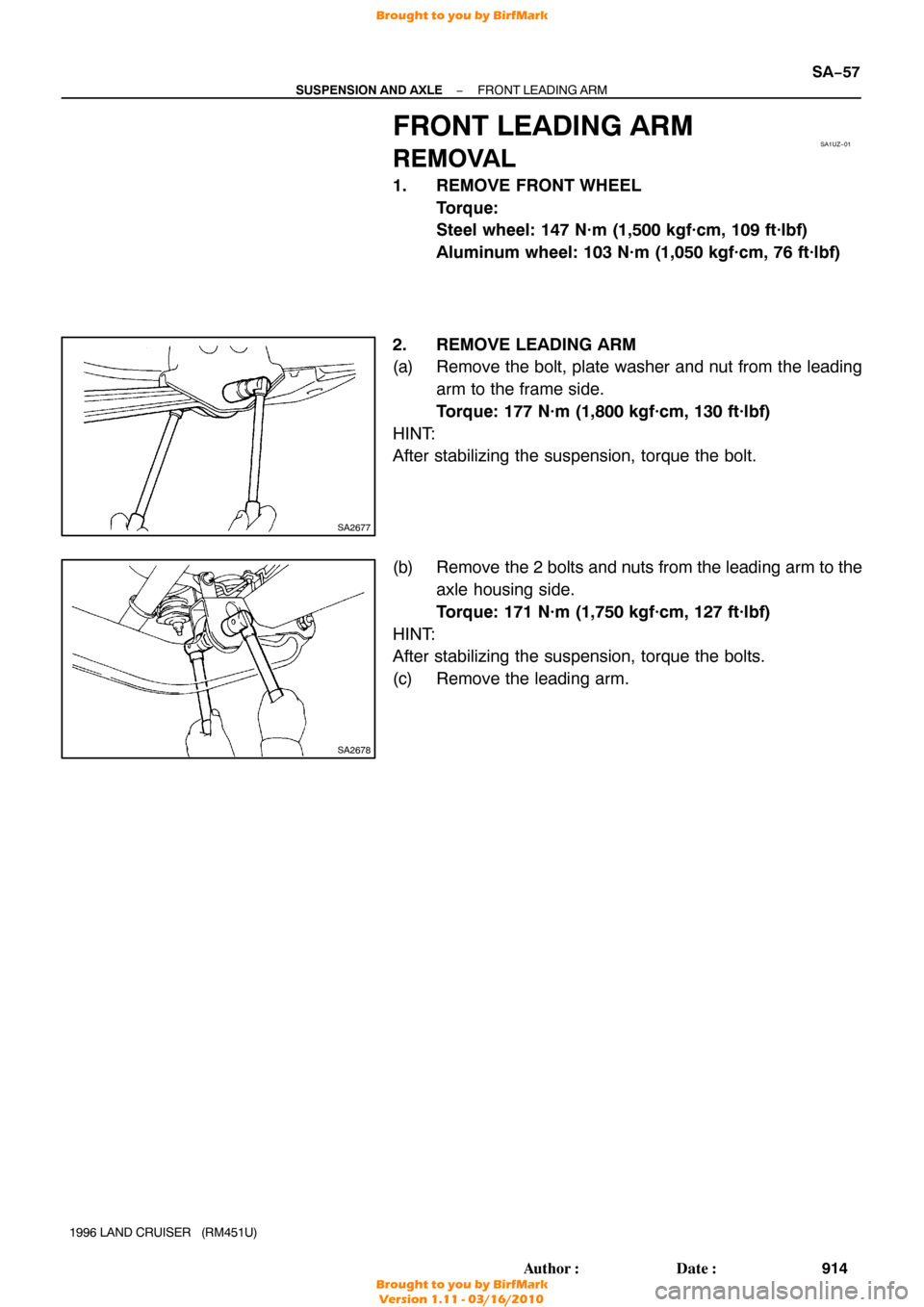
2. DISCONNECT LA TERAL CONTROL ROD FROM AXLE
HOUSING
Remove the bolt and disconnect the lateral control rod from the
axle housing.
Torque: 171 N·m (1,750 kgf·cm, 127 ft·lbf)
HINT:
After stabilizing the suspension, torque the bolt.
3. REMOVE LATERAL CONTROL ROD FROM FRAME
Remove the nut, bolt and lateral control rod. Torque: 171 N·m (1,750 kgf·cm, 127 ft·lbf)
HINT:
After stabilizing the suspension, torque the bolt.
Brought to you by BirfMark
Brought to you by BirfMark
Version 1.11 - 03/16/2010
Page 1120 of 1399
SA1UZ−01
SA2677
SA2678
−
SUSPENSION AND AXLE FRONT LEADING ARM
SA−57
914
Author�: Date�:
1996 LAND CRUISER (RM451U)
FRONT LEADING ARM
REMOVAL
1. REMOVE FRONT WHEEL
Torque:
Steel wheel: 147 N·m (1,500 kgf·cm, 109 ft·lbf)
Aluminum wheel: 103 N·m (1,050 kgf·cm, 76 ft·lbf)
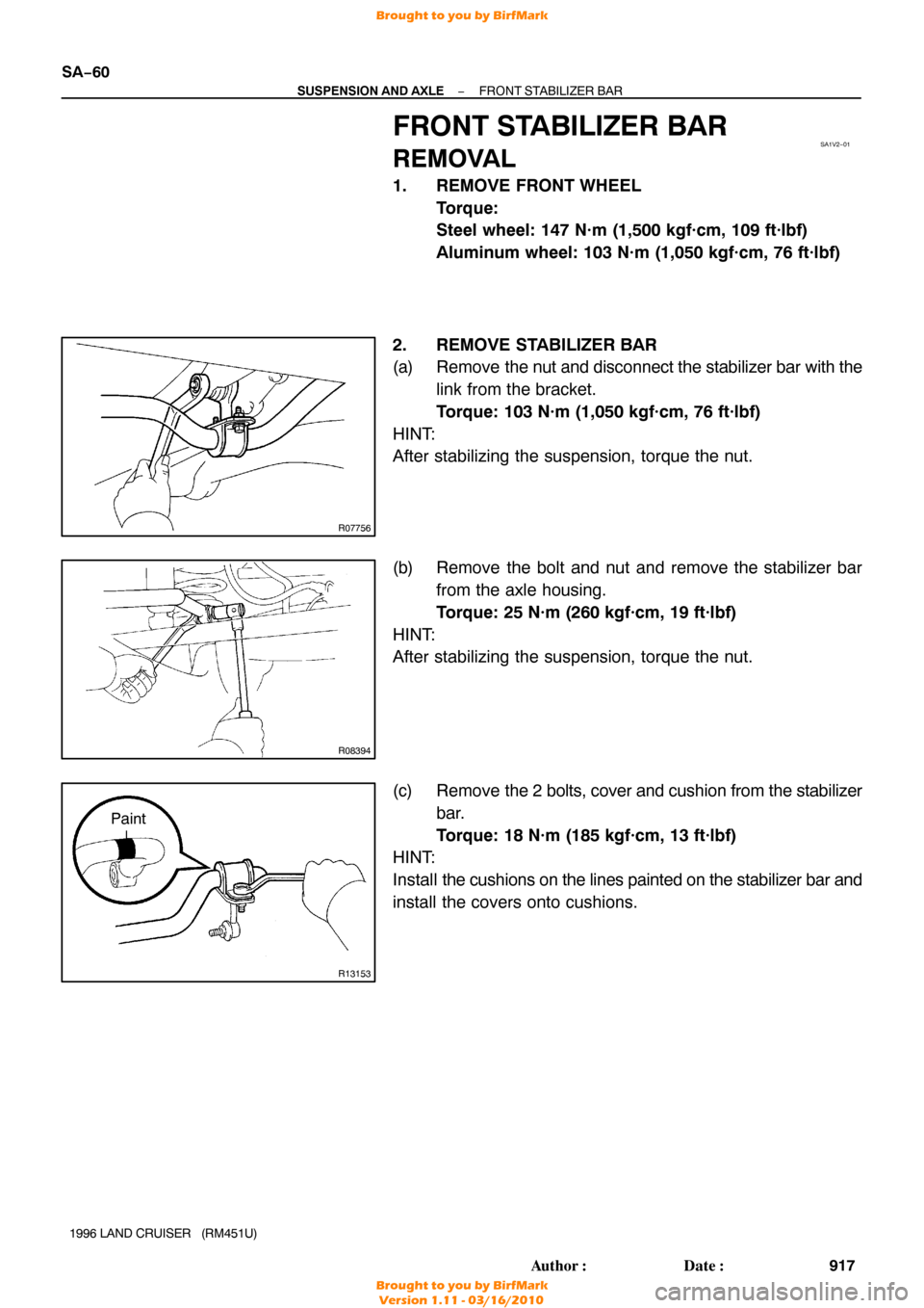
2. REMOVE LEADING ARM
(a) Remove the bolt, plate washer and nut from the leading arm to the frame side.
Torque: 177 N·m (1,800 kgf·cm, 130 ft·lbf)
HINT:
After stabilizing the suspension, torque the bolt.
(b) Remove the 2 bolts and nuts from the leading arm to the axle housing side.
Torque: 171 N·m (1,750 kgf·cm, 127 ft·lbf)
HINT:
After stabilizing the suspension, torque the bolts.
(c) Remove the leading arm.
Brought to you by BirfMark
Brought to you by BirfMark
Version 1.11 - 03/16/2010
Page 1123 of 1399
SA1V2−01
R07756
R08394
R13153
Paint
SA−60
−
SUSPENSION AND AXLE FRONT STABILIZER BAR
917
Author�: Date�:
1996 LAND CRUISER (RM451U)
FRONT STABILIZER BAR
REMOVAL
1. REMOVE FRONT WHEEL
Torque:
Steel wheel: 147 N·m (1,500 kgf·cm, 109 ft·lbf)
Aluminum wheel: 103 N·m (1,050 kgf·cm, 76 ft·lbf)
2. REMOVE STABILIZER BAR
(a) Remove the nut and disconnect the stabilizer bar with the
link from the bracket.
Torque: 103 N·m (1,050 kgf·cm, 76 ft·lbf)
HINT:
After stabilizing the suspension, torque the nut.
(b) Remove the bolt and nut and remove the stabilizer bar from the axle housing.
Torque: 25 N·m (260 kgf·cm, 19 ft·lbf)
HINT:
After stabilizing the suspension, torque the nut.
(c) Remove the 2 bolts, cover and cushion from the stabilizer
bar.
Torque: 18 N·m (185 kgf·cm, 13 ft·lbf)
HINT:
Install the cushions on the lines painted on the stabilizer bar and
install the covers onto cushions.
Brought to you by BirfMark
Brought to you by BirfMark
Version 1.11 - 03/16/2010
Page 1133 of 1399
W00498
OK
−0.2 − 0.9 mm
SA−70
−
SUSPENSION AND AXLE REAR AXLE HUB
1996 LAND CRUISER (RM451U)
(g) Check the distance between top surface of axle housing
and the lock nut.
Standard distance:
−0.2 − 0.9 mm (−0.0079 − 0.0354 in.)
If the distance is greater than the specification, reassemble the
lock nut plate.
(h) Check that the hub with disc rotates smoothly and hub has no axial play.
5. INSTALL BEARING LOCK NUT SCREW
Tighten the 2 lock nut screws. Torque: 5.4 N·m (55 kgf·cm, 48 in.·lbf)
6. CONNECT ABS SPEED SENSOR
Connect the ABS speed sensor install the bolt.
Torque: 18 N·m (185 kgf·cm, 13 ft·lbf)
7. INSTALL BRAKE CALIPER (See page BR−38 )
8. INSTALL REAR AXLE SHAFT (See page SA−65 )
9. INSTALL REAR WHEEL Torque:
Steel wheel: 147 N·m (1,500 kgf·cm, 109 ft·lbf)
Aluminum wheel: 103 N·m (1,050 kgf·cm, 76 ft·lbf)
10. CHECK ABS SPEED SENSOR SIGNAL (See page DI−190 )
Brought to you by BirfMark
Brought to you by BirfMark
Version 1.11 - 03/16/2010
Page 1176 of 1399

REMOVAL
1. REMOVE REAR WHEEL
Torque:
Steel wheel: 147 N·m (1,500 kgf·cm, 109 ft·")
SA1VP−01
R08418
−
SUSPENSION AND AXLE COIL SPRING AND REAR SHOCK ABSORBER
SA−11 3
1996 LAND CRUISER (RM451U)
REMOVAL
1. REMOVE REAR WHEEL
Torque:
Steel wheel: 147 N·m (1,500 kgf·cm, 109 ft·lbf)
Aluminum wheel: 103 N·m (1,050 kgf·cm, 76 ft·lbf)
2. REMOVE REAR SHOCK ABSORBER
(a) Remove the lower bolt holding the shock absorber from the rear axle housing.
Torque: 64 N·m (650 kgf·cm, 47 ft·lbf)
(b) Remove the retainer and 2 cushions, disconnect the shock absorber.
(c) Remove the 2 upper bolts and shock absorber. Torque: 50 N·m (510 kgf·cm, 37 ft·lbf)
(d) Remove these parts from the shock absorber:
�Nut
�3 Retainers
�2 Cushions
�Bracket
Torque: 69 N·m (700 kgf·cm, 51 ft·lbf)
3. DISCONNECT STABILIZER BAR BRACKETS FROM
REAR AXLE HOUSING (See page SA−124 )
4. DISCONNECT LATERAL CONTROL ROD FROM REAR AXLE HOUSING (See page SA−11 8 )
5. REMOVE COIL SPRING
(a) Begin to lower the axle housing.
HINT:
Be careful not to snap the brake line and parking brake cable.
(b) With lowering the rear axle housing, remove the coil spring and insulator.
HINT:
Check that the coil spring end is installed correctly.
If the coil spring end is not in the correct position, reinstall the
coil spring.
Brought to you by BirfMark
Brought to you by BirfMark
Version 1.11 - 03/16/2010
Page 1181 of 1399
SA1VU−01
SA−11 8
−
SUSPENSION AND AXLE REAR LATERAL CONTROL ROD
975
Author�: Date�:
1996 LAND CRUISER (RM451U)
REAR LATERAL CONTROL ROD
REMOVAL
1. REMOVE REAR WHEEL
Torque:
Steel wheel: 147 N·m (1,500 kgf·cm, 109 ft·lbf)
Aluminum wheel: 103 N·m (1,050 kgf·cm, 76 ft·lbf)
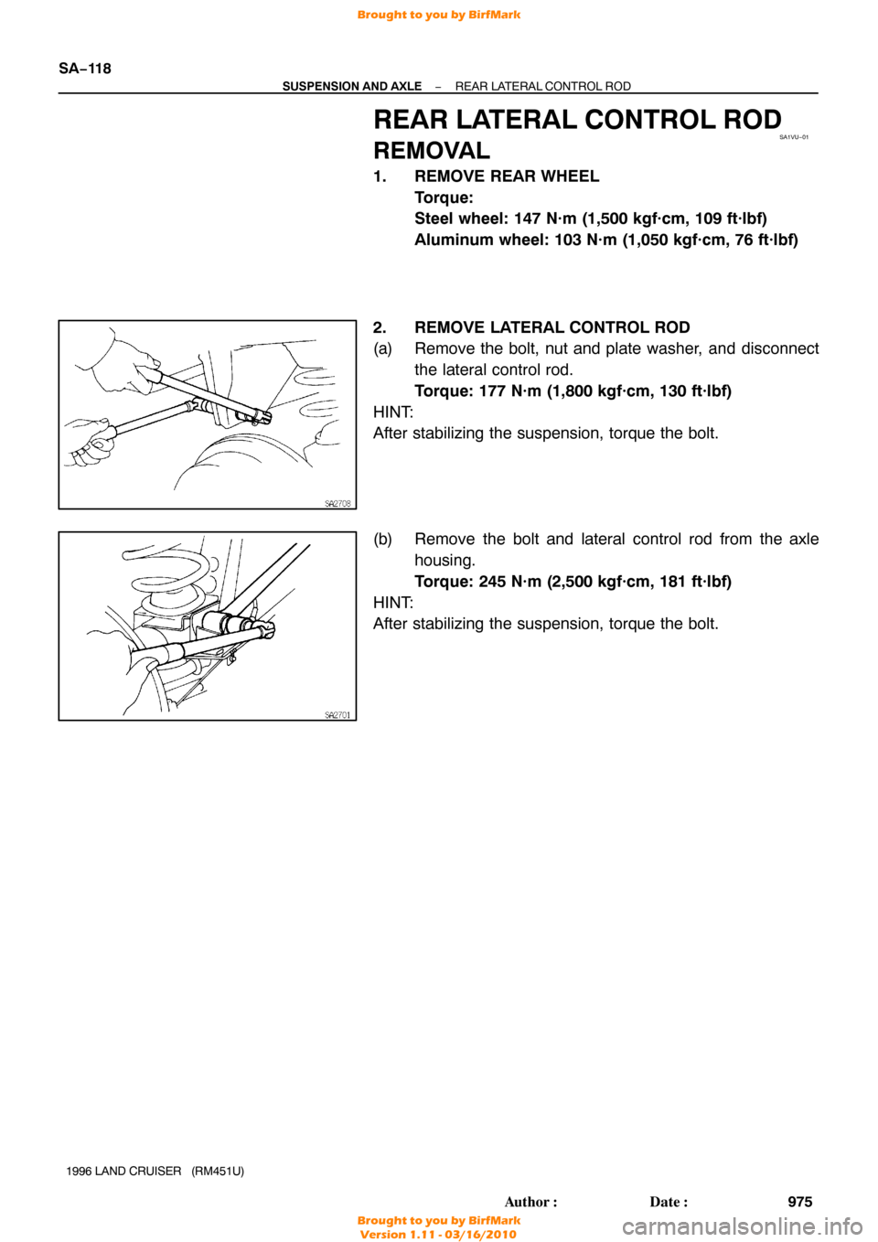
2. REMOVE LATERAL CONTROL ROD
(a) Remove the bolt, nut and plate washer, and disconnect the lateral control rod.
Torque: 177 N·m (1,800 kgf·cm, 130 ft·lbf)
HINT:
After stabilizing the suspension, torque the bolt.
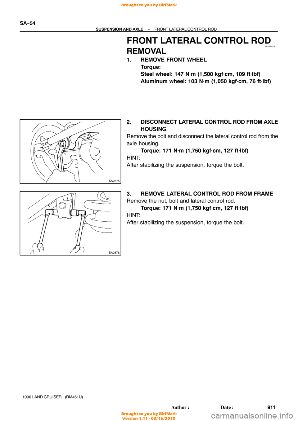
(b) Remove the bolt and lateral control rod from the axle housing.
Torque: 245 N·m (2,500 kgf·cm, 181 ft·lbf)
HINT:
After stabilizing the suspension, torque the bolt.
Brought to you by BirfMark
Brought to you by BirfMark
Version 1.11 - 03/16/2010
Page 1184 of 1399
SA1VX−01
−
SUSPENSION AND AXLE REAR UPPER AND LOWER CONTROL ARM
SA−121
978
Author�: Date�:
1996 LAND CRUISER (RM451U)
REAR UPPER AND LOWER
CONTROL ARM
REMOVAL
1. REMOVE REAR WHEEL
Torque:
Steel wheel: 147 N·m (1,500 kgf·cm, 109 ft·lbf)
Aluminum wheel: 103 N·m (1,050 kgf·cm, 76 ft·lbf)
2. REMOVE UPPER CONTROL ARM
Remove the 2 bolts, plate washers, nuts and upper control arm
from the frame. Torque: 177 N·m (1,800 kgf·cm, 130 ft·lbf)
HINT:
After stabilizing the suspension, torque the bolt.
3. REMOVE LOWER CONTROL ARM
Remove the 2 bolts, plate washers, nuts and lower control arm
from the frame. Torque: 177 N·m (1,800 kgf·cm, 130 ft·lbf)
HINT:
After stabilizing the suspension, torque the bolt.
Brought to you by BirfMark
Brought to you by BirfMark
Version 1.11 - 03/16/2010

(c) Torque the 8 bolts.
Torque: 47 N·m (475 kgf·cm, 34 ft·lbf)
13. CONNECT ABS SPEED SENSOR
Connect the")

(g) Check the distance between top surface of axle housing
and the lock nut.
Standard distance")