Page 1192 of 1399

(d) Observe the following precautio")
P09286
New O−ring
Grommet Injector
Delivery Pipe WRONG
CORRECT
P09401
Fuel Return Hose
SF−4
−
SFI SFI SYSTEM
632
Author�: Date�:
1996 LAND CRUISER (RM451U)
(d) Observe the following precautions when removing and
installing the injectors.
(1) Never reuse the O −ring.
(2) When placing a new O −ring on the injector, take
care not to damage it in any way.
(3) Coat a new O −ring with spindle oil or gasoline be-
fore installing −never use engine, gear or brake oil.
(e) Install the injector to the delivery pipe and intake manifold
as shown in the illustration.
(f) Check that there are no fuel leaks after doing mainte- nance anywhere on the fuel system.
(1) Remove the fuse cover on the instrument panel.
(2) Connect the TOYOTA hand− held tester to the
DLC3.
(3) Turn the ignition switch ON and TOYOTA hand −
held tester main switch ON.
NOTICE:
Do not start the engine. (4) Select the active test mode on the TOYOTA hand−held tester.
(5) Please refer to the TOYOTA hand −held tester oper-
ator ’s manual for further details.
If you have no T OYOTA hand−held tester, connect the positive
(+) and negative ( −) leads from the battery to the fuel pump con-
nector (See page SF−14 ).
(6) Pinch the fuel return hose. The pressure in the high
pressure line will rise to approx. 392 kPa (4 kgf/cm
2,
57 psi). In this state, check to see that there are no
leaks from any part of the fuel system.
NOTICE:
Always pinch the hose. Avoid bending as it may cause the
hose to crack.
(7) Turn the ignition switch to LOCK.
(8) Disconnect the TOYOTA hand −held tester from the
DLC3.
Brought to you by BirfMark
Brought to you by BirfMark
Version 1.11 - 03/16/2010
Page 1207 of 1399
SF0Y1−06
SF−22
−
SFI FUEL PRESSURE REGULATOR
1996 LAND CRUISER (RM451U)
INSTALLATION
1. INSTALL FUEL PRESSURE REGULATOR
(a) Fully loosen the lock nut on the pressure regulator.
(b) Apply a light coat of gasoline to a new O −ring, and install
it to the pressure regulator.
(c) Insert the pressure regulator into the delivery pipe by hand completely.
(d) Turn the pressure regulator counterclockwise until the fuel outlet port faces in the direction indicated in the il-
lustration.
(e) Tighten the lock nut. Torque: 25 N·m (250 kgf·cm, 18 ft·lbf)
2. CONNECT FUEL RETURN HOSE TO FUEL PRES-
SURE REGULATOR
3. CONNECT V ACUUM SENSING HOSE TO FUEL PRES-
SURE REGULATOR
4. START ENGINE AND CHECK FOR FUEL LEAKAGE
Brought to you by BirfMark
Brought to you by BirfMark
Version 1.11 - 03/16/2010
Page 1208 of 1399
SF0Y1−06
SF−22
−
SFI FUEL PRESSURE REGULATOR
1996 LAND CRUISER (RM451U)
INSTALLATION
1. INSTALL FUEL PRESSURE REGULATOR
(a) Fully loosen the lock nut on the pressure regulator.
(b) Apply a light coat of gasoline to a new O −ring, and install
it to the pressure regulator.
(c) Insert the pressure regulator into the delivery pipe by hand completely.
(d) Turn the pressure regulator counterclockwise until the fuel outlet port faces in the direction indicated in the il-
lustration.
(e) Tighten the lock nut. Torque: 25 N·m (250 kgf·cm, 18 ft·lbf)
2. CONNECT FUEL RETURN HOSE TO FUEL PRES-
SURE REGULATOR
3. CONNECT V ACUUM SENSING HOSE TO FUEL PRES-
SURE REGULATOR
4. START ENGINE AND CHECK FOR FUEL LEAKAGE
Brought to you by BirfMark
Brought to you by BirfMark
Version 1.11 - 03/16/2010
Page 1216 of 1399

(f) Install the grommet and O−ring to the injector.
(g) Connect SST (union and hose) to the injector, and hold
the injector and u")
FI4848
FI4849
SF−30
−
SFI INJECTOR
1996 LAND CRUISER (RM451U)
(f) Install the grommet and O−ring to the injector.
(g) Connect SST (union and hose) to the injector, and hold
the injector and union with SST (clamp).
SST 09268−41046
(h) Put the injector into the graduated cylinder.
HINT:
Install a suitable vinyl hose onto the injector to prevent gasoline
from splashing out.
(i) Remove the fuse cover on the instrument panel.
(j) Connect the TOYOTA hand−held tester to the DLC3.
(k) Turn the ignition switch ON and TOYOTA hand−held tes-
ter main switch ON.
NOTICE:
Do not start the engine.
(l) Select the active test mode on the TOYOTA hand −held
tester.
(m) Please refer to the TOYOTA hand −held tester operator’s
manual for further details.
(n) If you have no TOYOTA hand−held tester, connect the positive (+) and negative (−) leads from the battery to the
fuel pump connector (See page SF−14)
(o) Connect SST (wire) to the injector and battery for 15 se- conds, and measure the injection volume with a gra-
duated cylinder. Test each injector 2 or 3 times.
SST 09842−30070
Volume:
69 − 88 cm
3 (4.2 − 5.4 cu in.) per 15 seconds
Difference between each injector:
5 cm
3 (0.3 cu in.) or less
If the injection volume is not as specified, replace the injector.
2. INSPECT LEAKAGE
(a) In the condition above, disconnect the test probes of SST (wire) from the battery and check the fuel leakage from
the injector.
SST 09842−30070
Fuel drop: One drop or less per minute
(b) Turn the ignition switch to LOCK.
(c) Disconnect the negative ( −) terminal cable from the bat-
tery.
Brought to you by BirfMark
Brought to you by BirfMark
Version 1.11 - 03/16/2010
Page 1222 of 1399
SF0OZ−12
SF−36
−
SFI FUEL TANK AND LINE
664
Author�: Date�:
1996 LAND CRUISER (RM451U)
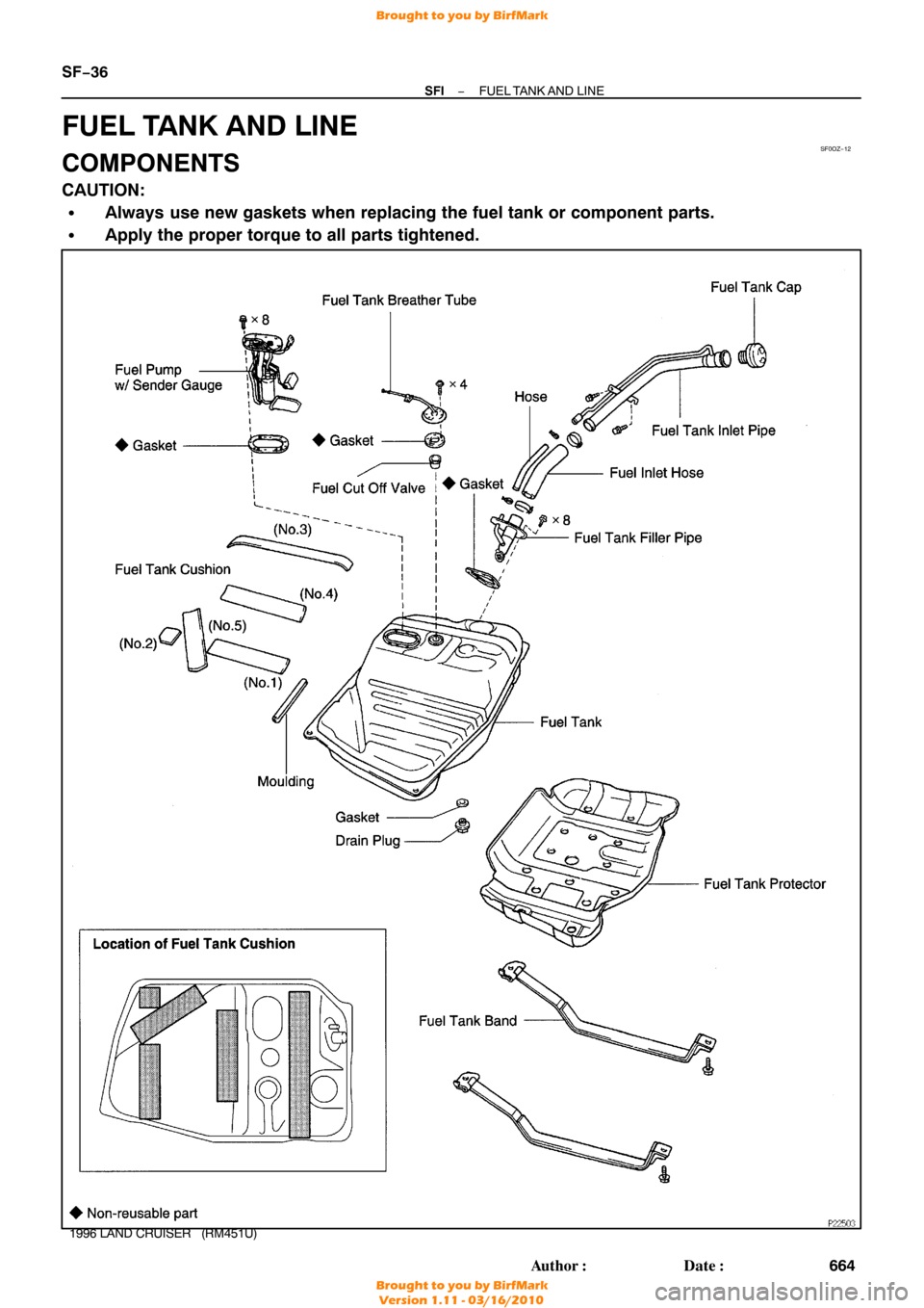
FUEL TANK AND LINE
COMPONENTS
CAUTION:
�Always use new gaskets when replacing the fuel tank or component parts.
�Apply the proper torque to all parts tightened.
Brought to you by BirfMark
Brought to you by BirfMark
Version 1.11 - 03/16/2010
Page 1223 of 1399
BO0919
Z00085
FU0041
SF0P0−06
−
SFI FUEL TANK AND LINE
SF−37
1996 LAND CRUISER (RM451U)
INSPECTION
INSPECT FUEL TANK AND LINE
(a) Check the fuel lines for cracks or leakage, and all connec-
tions for deformation.
(b) Check the fuel tank vapor vent system hoses and connec-
tions for looseness, sharp bends or damage.
(c) Check the fuel tank for deformation, cracks fuel leakage
or tank band looseness.
(d) Check the filler neck for damage or fuel leakage.
(e) Hose and tube connections are as shown in the illustra- tion.
If a problem is found, repair or replace the part as necessary.
Brought to you by BirfMark
Brought to you by BirfMark
Version 1.11 - 03/16/2010
Page 1313 of 1399

TORQUE SPECIFICATION
Part tightenedN·mkgf·cmft·lbf
Fuel line for union bolt
for flare nut29
30300
31022
22
Second sea")
SS1ET−01
SS−12
−
SERVICE SPECIFICATIONS SFI
1996 LAND CRUISER (RM451U)
TORQUE SPECIFICATION
Part tightenedN·mkgf·cmft·lbf
Fuel line for union bolt
for flare nut29
30300
31022
22
Second seat x Body3940029
Fuel pump bracket assembly x Fuel tank3.94035 in.·lbf
Fuel inlet hose x Fuel filter2930022
Fuel inlet pipe x Fuel filter2930022
Fuel filter x Intake manifold2121015
Fuel pressure regulator x Delivery pipe2525018
Delivery pipe x Intake manifold2121015
Fuel inlet pipe x Delivery pipe Union bolt
Bolt29
20300
20022
14
Fuel inlet pipe x Fuel filter2930022
Fuel return pipe x Intake manifold2020014
Air intake chamber x Intake manifold2121015
Intake manifold stay x Air intake chamber3636026
Intake manifold stay x Cylinder block3636026
PS reservoir tank x Air intake chamber1818513
Heater inlet pipe x Air intake chamber2020014
Drain plug x Fuel tank6.56557 in.·lbf
Fuel tank breather tube x Fuel tank1.51513 in.·lbf
Fuel tank filler pipe x Fuel tank3.53531 in.·lbf
Fuel tank band x Body3940029
MAF meter x Bracket6.97061 in.·lbf
MAF meter x Air cleaner cap6.97061 in.·lbf
Throttle body x Air intake chamber2121015
Fuel pump resistor x Body1818513
ECT sensor x Cylinder head24.525017.5
EGR gas temperature sensor x Air intake chamber2020014
Knock sensor x Cylinder block4445033
Brought to you by BirfMark
Brought to you by BirfMark
Version 1.11 - 03/16/2010
Page:
< prev 1-8 9-16 17-24

INSTALLATION
1. INSTALL FUEL PRESSURE REGULATOR
(a) Fully loosen the lock nut on the pressure regulator.
(b) Apply a lig")

INSTALLATION
1. INSTALL FUEL PRESSURE REGULATOR
(a) Fully loosen the lock nut on the pressure regulator.
(b) Apply a lig")

INSPECTION
INSPECT FUEL TANK AND LINE
(a) Check the fuel lines for cracks or leakage, and all connec-
t")