Page 1133 of 1399
W00498
OK
−0.2 − 0.9 mm
SA−70
−
SUSPENSION AND AXLE REAR AXLE HUB
1996 LAND CRUISER (RM451U)
(g) Check the distance between top surface of axle housing
and the lock nut.
Standard distance:
−0.2 − 0.9 mm (−0.0079 − 0.0354 in.)
If the distance is greater than the specification, reassemble the
lock nut plate.
(h) Check that the hub with disc rotates smoothly and hub has no axial play.
5. INSTALL BEARING LOCK NUT SCREW
Tighten the 2 lock nut screws. Torque: 5.4 N·m (55 kgf·cm, 48 in.·lbf)
6. CONNECT ABS SPEED SENSOR
Connect the ABS speed sensor install the bolt.
Torque: 18 N·m (185 kgf·cm, 13 ft·lbf)
7. INSTALL BRAKE CALIPER (See page BR−38 )
8. INSTALL REAR AXLE SHAFT (See page SA−65 )
9. INSTALL REAR WHEEL Torque:
Steel wheel: 147 N·m (1,500 kgf·cm, 109 ft·lbf)
Aluminum wheel: 103 N·m (1,050 kgf·cm, 76 ft·lbf)
10. CHECK ABS SPEED SENSOR SIGNAL (See page DI−190 )
Brought to you by BirfMark
Brought to you by BirfMark
Version 1.11 - 03/16/2010
Page 1176 of 1399
SA1VP−01
R08418
−
SUSPENSION AND AXLE COIL SPRING AND REAR SHOCK ABSORBER
SA−11 3
1996 LAND CRUISER (RM451U)
REMOVAL
1. REMOVE REAR WHEEL
Torque:
Steel wheel: 147 N·m (1,500 kgf·cm, 109 ft·lbf)
Aluminum wheel: 103 N·m (1,050 kgf·cm, 76 ft·lbf)
2. REMOVE REAR SHOCK ABSORBER
(a) Remove the lower bolt holding the shock absorber from the rear axle housing.
Torque: 64 N·m (650 kgf·cm, 47 ft·lbf)
(b) Remove the retainer and 2 cushions, disconnect the shock absorber.
(c) Remove the 2 upper bolts and shock absorber. Torque: 50 N·m (510 kgf·cm, 37 ft·lbf)
(d) Remove these parts from the shock absorber:
�Nut
�3 Retainers
�2 Cushions
�Bracket
Torque: 69 N·m (700 kgf·cm, 51 ft·lbf)
3. DISCONNECT STABILIZER BAR BRACKETS FROM
REAR AXLE HOUSING (See page SA−124 )
4. DISCONNECT LATERAL CONTROL ROD FROM REAR AXLE HOUSING (See page SA−11 8 )
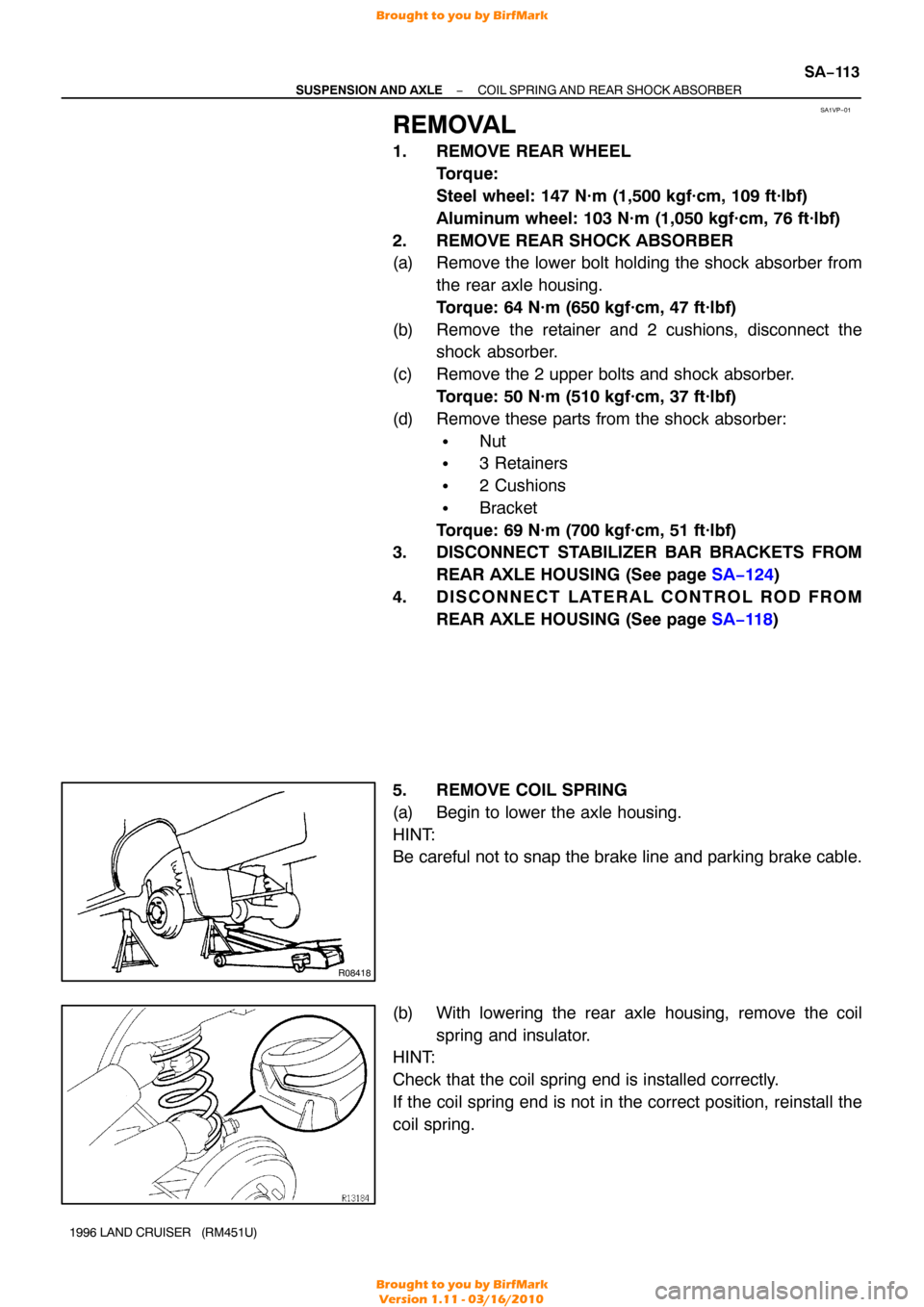
5. REMOVE COIL SPRING
(a) Begin to lower the axle housing.
HINT:
Be careful not to snap the brake line and parking brake cable.
(b) With lowering the rear axle housing, remove the coil spring and insulator.
HINT:
Check that the coil spring end is installed correctly.
If the coil spring end is not in the correct position, reinstall the
coil spring.
Brought to you by BirfMark
Brought to you by BirfMark
Version 1.11 - 03/16/2010
Page 1192 of 1399
P09286
New O−ring
Grommet Injector
Delivery Pipe WRONG
CORRECT
P09401
Fuel Return Hose
SF−4
−
SFI SFI SYSTEM
632
Author�: Date�:
1996 LAND CRUISER (RM451U)
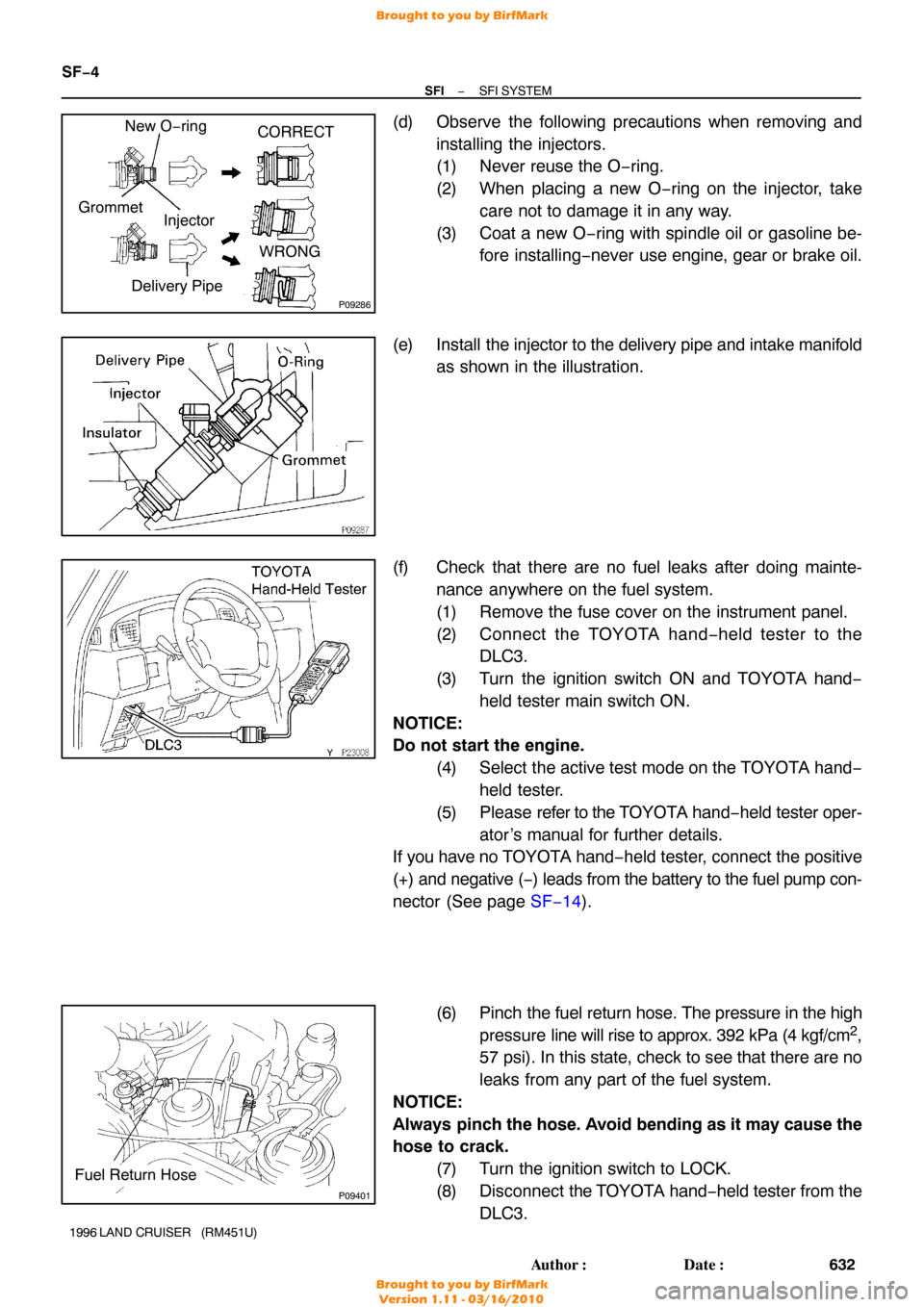
(d) Observe the following precautions when removing and
installing the injectors.
(1) Never reuse the O −ring.
(2) When placing a new O −ring on the injector, take
care not to damage it in any way.
(3) Coat a new O −ring with spindle oil or gasoline be-
fore installing −never use engine, gear or brake oil.
(e) Install the injector to the delivery pipe and intake manifold
as shown in the illustration.
(f) Check that there are no fuel leaks after doing mainte- nance anywhere on the fuel system.
(1) Remove the fuse cover on the instrument panel.
(2) Connect the TOYOTA hand− held tester to the
DLC3.
(3) Turn the ignition switch ON and TOYOTA hand −
held tester main switch ON.
NOTICE:
Do not start the engine. (4) Select the active test mode on the TOYOTA hand−held tester.
(5) Please refer to the TOYOTA hand −held tester oper-
ator ’s manual for further details.
If you have no T OYOTA hand−held tester, connect the positive
(+) and negative ( −) leads from the battery to the fuel pump con-
nector (See page SF−14 ).
(6) Pinch the fuel return hose. The pressure in the high
pressure line will rise to approx. 392 kPa (4 kgf/cm
2,
57 psi). In this state, check to see that there are no
leaks from any part of the fuel system.
NOTICE:
Always pinch the hose. Avoid bending as it may cause the
hose to crack.
(7) Turn the ignition switch to LOCK.
(8) Disconnect the TOYOTA hand −held tester from the
DLC3.
Brought to you by BirfMark
Brought to you by BirfMark
Version 1.11 - 03/16/2010
Page 1212 of 1399
SF1EN−01
SF−26
−
SFI INJECTOR
1996 LAND CRUISER (RM451U)
REMOVAL
1. DRAIN ENGINE COOLANT
2. DISCONNECT CRUISE CONTROL ACTUATOR CABLE
3. DISCONNECT ACCELERATOR CABLE
4. DISCONNECT THROTTLE CABLE
5. DISCONNECT NO.2 PCV HOSE
6. DISCONNECT AIR CLEANER HOSE
7. REMOVE EGR VACUUM MODULATOR AND VALVE (See page EC−10 )
8. REMOVE BOLT HOLDING HEATER INLET PIPE AND AIR INTAKE CHAMBER
9. DISCONNECT NO.1 PCV HOSE
10. DISCONNECT VACUUM SENSING HOSE
11. DISCONNECT NO.2 WATER BYPASS HOSE
12. DISCONNECT EVAP HOSE
13. DISCONNECT BRAKE BOOSTER HOSE
14. DISCONNECT THROTTLE POSITION SENSOR CON- NECTOR
15. DISCONNECT IDLE AIR CONTROL VALVE CONNEC-
TOR
16. DISCONNECT CONNECTOR FOR EMISSION CON- TROL VALVE SET ASSEMBLY
17. DISCONNECT EGR GAS TEMP. SENSOR CONNEC-
TOR
Brought to you by BirfMark
Brought to you by BirfMark
Version 1.11 - 03/16/2010
Page 1220 of 1399

SF−34
−
SFI INJECTOR
1996 LAND CRUISER (RM451U)
7. INSTALL INTAKE MANIFOLD STAY
Install the intake manifold stay with the 2 bolts.
Torque: 36 N·m (360 kgf·cm, 26 ft·lbf)
8. CONNECT GROUND STRAP
9. INSTALL ENGINE OIL DIPSTICK
10. CONNECT PS RESERVOIR TANK
Connect the reservoir tank with the 3 bolts. Torque: 18 N·m (185 kgf·cm, 13 ft·lbf)
11. CONNECT EGR GAS TEMP. SENSOR CONNECTOR
12. CONNECT CONNECTOR FOR EMISSION CONTROL VALVE SET ASSEMBLY
13. CONNECT IDLE AIR CONTROL VALVE CONNECTOR
14. CONNECT THROTTLE POSITION SENSOR CONNEC- TOR
15. CONNECT BRAKE BOOSTER HOSE
16. CONNECT EVAP HOSE
17. CONNECT NO.2 WATER BYPASS HOSE
18. CONNECT VACUUM SENSING HOSE
19. CONNECT NO.1 PCV HOSE
20. INSTALL BOLT HOLDING HEATER INLET PIPE AND AIR INTAKE CHAMBER
Torque: 20 N·m (200 kgf·cm, 14 ft·lbf)
21. INSTALL EGR VALVE AND VACUUM MODULATOR (See page EC−10 )
22. CONNECT THROTTLE CABLE
23. CONNECT ACCELERATOR CABLE
24. CONNECT CRUISE CONTROL ACTUATOR CABLE
25. CONNECT AIR CLEANER HOSE
26. CONNECT NO.2 PCV HOSE
Brought to you by BirfMark
Brought to you by BirfMark
Version 1.11 - 03/16/2010
Page 1269 of 1399
SR−18
−
STEERING TILT STEERING COLUMN
1996 LAND CRUISER (RM451U)
11. INSTALL 3 TENSION SPRINGS
12. INSTALL COMPRESSION SPRING
(a) Install the 2 bushings to the spring.
(b) Torque the bolt.
Torque: 7.8 N·m (80 kgf·cm, 69 in.·lbf)
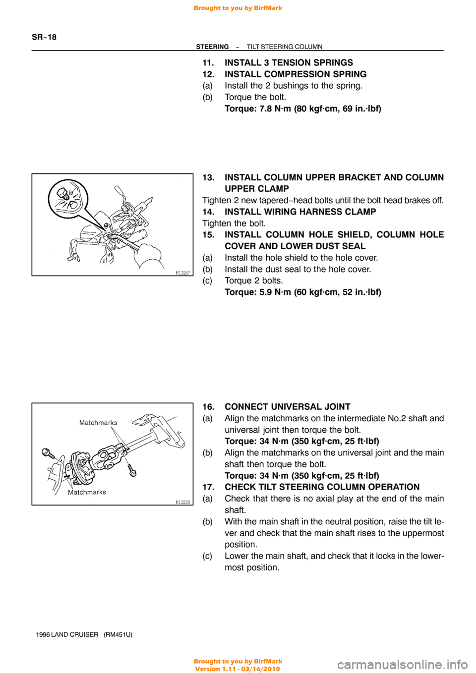
13. INSTALL COLUMN UPPER BRACKET AND COLUMN UPPER CLAMP
Tighten 2 new tapered −head bolts until the bolt head brakes off.
14. INSTALL WIRING HARNESS CLAMP
Tighten the bolt.
15. INSTALL COLUMN HOLE SHIELD, COLUMN HOLE COVER AND LOWER DUST SEAL
(a) Install the hole shield to the hole cover.
(b) Install the dust seal to the hole cover.
(c) Torque 2 bolts. Torque: 5.9 N·m (60 kgf·cm, 52 in.·lbf)
16. CONNECT UNIVERSAL JOINT
(a) Align the matchmarks on the intermediate No.2 shaft and
universal joint then torque the bolt.
Torque: 34 N·m (350 kgf·cm, 25 ft·lbf)
(b) Align the matchmarks on the universal joint and the main shaft then torque the bolt.
Torque: 34 N·m (350 kgf·cm, 25 ft·lbf)
17. CHECK TILT STEERING COLUMN OPERATION
(a) Check that there is no axial play at the end of the main
shaft.
(b) With the main shaft in the neutral position, raise the tilt le- ver and check that the main shaft rises to the uppermost
position.
(c) Lower the main shaft, and check that it locks in the lower-
most position.
Brought to you by BirfMark
Brought to you by BirfMark
Version 1.11 - 03/16/2010
Page 1334 of 1399
SS1ED−02
−
SERVICE SPECIFICATIONS SUSPENSION AND AXLE
SS−33
1996 LAND CRUISER (RM451U)
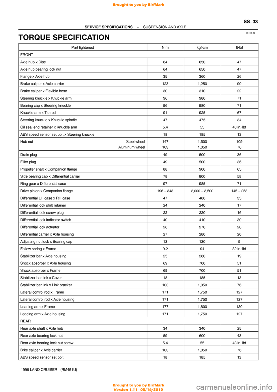
TORQUE SPECIFICATION
Part tightenedN·mkgf·cmft·lbf
FRONT
Axle hub x Disc6465047
Axle hub bearing lock nut6465047
Flange x Axle hub3536026
Brake caliper x Axle carrier1231,25090
Brake caliper x Flexible hose3031022
Steering knuckle x Knuckle arm9698071
Bearing cap x Steering knuckle9698071
Knuckle arm x Tie rod9192567
Steering knuckle x Knuckle spindle4747534
Oil seal end retainer x Knuckle arm5.45548 in.·lbf
ABS speed sensor set bolt x Steering knuckle1818513
Hub nut Steel wheel
Aluminum wheel147
1031,500
1,050109 76
Drain plug4950036
Filler plug4950036
Propeller shaft x Companion flange8890065
Side bearing cap x Differential carrier7880058
Ring gear x Differential case9798571
Drive pinion x Companion flange196 − 3432,000 − 3,500145 − 253
Differential LH case x RH case4748035
Differential lock shift retainer2424017
Differential lock screw plug2222016
Differential lock indicator switch4041030
Differential lock actuator2627020
Differential carrier x Axle housing2728020
Adjusting nut lock x Bearing cap131309
Follow spring x Frame9.29482 in.·lbf
Stabilizer bar x Axle housing2526019
Shock absorber x Axle housing6970051
Shock absorber x Frame6970051
Stabilizer bar link x Cover1818513
Stabilizer bar link x Link bracket1031,05076
Lateral control rod x Frame1711,750127
Lateral control rod x Axle housing1711,750127
Leading arm x Frame1771,800130
Leading arm x Axle housing1711,750127
REAR
Rear axle shaft x Axle hub3434025
Rear axle bearing lock nut5960043
Rear axle bearing lock nut screw5.45548 in.·lbf
Brke caliper x Axle carrier1031,05076
ABS speed sensor set bolt1818513
Brought to you by BirfMark
Brought to you by BirfMark
Version 1.11 - 03/16/2010
Page 1336 of 1399
SS1EE−02
−
SERVICE SPECIFICATIONS BRAKE
SS−35
158
Author�: Date�:
1996 LAND CRUISER (RM451U)
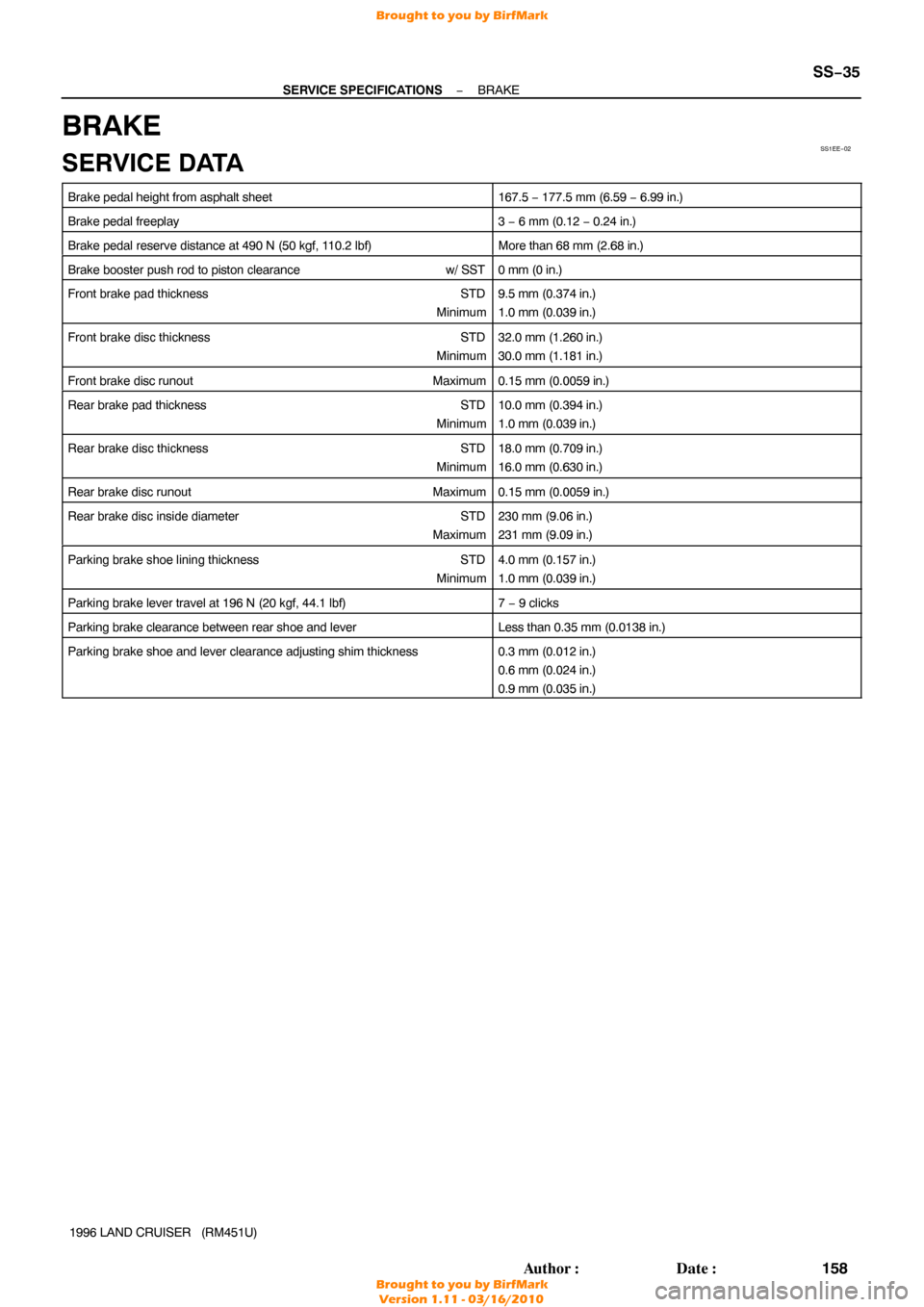
BRAKE
SERVICE DATA
Brake pedal height from asphalt sheet167.5 − 177.5 mm (6.59 − 6.99 in.)
Brake pedal freeplay3 − 6 mm (0.12 − 0.24 in.)
Brake pedal reserve distance at 490 N (50 kgf, 110.2 lbf)More than 68 mm (2.68 in.)
Brake booster push rod to piston clearance w/ SST0 mm (0 in.)
Front brake pad thickness STD
Minimum9.5 mm (0.374 in.)
1.0 mm (0.039 in.)
Front brake disc thickness STD
Minimum32.0 mm (1.260 in.)
30.0 mm (1.181 in.)
Front brake disc runout Maximum0.15 mm (0.0059 in.)
Rear brake pad thickness STD
Minimum10.0 mm (0.394 in.)
1.0 mm (0.039 in.)
Rear brake disc thickness STD
Minimum18.0 mm (0.709 in.)
16.0 mm (0.630 in.)
Rear brake disc runout Maximum0.15 mm (0.0059 in.)
Rear brake disc inside diameter STD
Maximum230 mm (9.06 in.)
231 mm (9.09 in.)
Parking brake shoe lining thickness STD
Minimum4.0 mm (0.157 in.)
1.0 mm (0.039 in.)
Parking brake lever travel at 196 N (20 kgf, 44.1 lbf)7 − 9 clicks
Parking brake clearance between rear shoe and leverLess than 0.35 mm (0.0138 in.)
Parking brake shoe and lever clearance adjusting shim thickness0.3 mm (0.012 in.)
0.6 mm (0.024 in.)
0.9 mm (0.035 in.)
Brought to you by BirfMark
Brought to you by BirfMark
Version 1.11 - 03/16/2010