Page 995 of 1399
PP2YI−01
PP−54
−
PREPARATION BRAKE
1996 LAND CRUISER (RM451U)
EQUIPMENT
Dial indicatorBrake disc
MicrometerBrake disc
Torque wrench
Vernier calipersBrake disc
Brought to you by BirfMark
Brought to you by BirfMark
Version 1.11 - 03/16/2010
Page 996 of 1399
PP2YJ−01
−
PREPARATION BRAKE
PP−55
1996 LAND CRUISER (RM451U)
LUBRICANT
ItemCapacityClassification
Brake fluid−SAE J1703 or FMVSS No. 116 DOT 3
Brought to you by BirfMark
Brought to you by BirfMark
Version 1.11 - 03/16/2010
Page 1068 of 1399

R05626
Front
Side+10
° +60
°
−10 °
FA0507
FA0018
A B
Front BA
A: Inside
B: Outside
−
SUSPENSION AND AXLE FRONT WHEEL ALIGNMENT
SA−5
862
Author�: Date�:
1996 LAND CRUISER (RM451U)
HINT:
The clamps opening must be positioned at the rear of the tie rod
end face within 60 °±10° from the vehicle axis.
6. INSPECT WHEEL ANGLE
(a) Remove the caps of the knuckle stopper bolts and check the steering angles.
(b) Turn the steering wheel fully, and measure the turning angle.
Inside wheel32°00’ − 35°00’
Outside wheel31 °00’ (Reference)
HINT:
When the steering wheel is fully turned, make sure that the
wheel is not touching the body or brake flexible hose.
If maximum steering angles differ from the standard value, ad-
just the wheel angle with the knuckle stopper bolts.
Torque: 44 N·m (450 kgf·cm, 33 ft·lbf)
If the wheel angle still cannot be adjusted within limits, inspect
and replace damaged or worn steering parts.
Brought to you by BirfMark
Brought to you by BirfMark
Version 1.11 - 03/16/2010
Page 1070 of 1399

SA1UB−01
SA2635
SST
−
SUSPENSION AND AXLE FRONT AXLE HUB
SA−7
1996 LAND CRUISER (RM451U)
REMOVAL
1. REMOVE FRONT WHEEL
2. REMOVE BRAKE CALIPER (See page BR−25 )
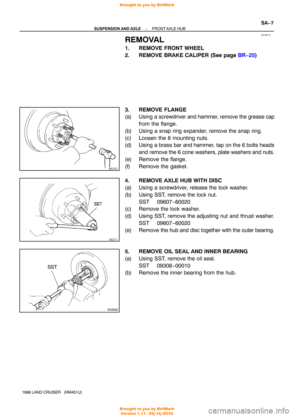
3. REMOVE FLANGE
(a) Using a screwdriver and hammer, remove the grease cap
from the flange.
(b) Using a snap ring expander, remove the snap ring.
(c) Loosen the 6 mounting nuts.
(d) Using a brass bar and hammer, tap on the 6 bolts heads and remove the 6 cone washers, plate washers and nuts.
(e) Remove the flange.
(f) Remove the gasket.
4. REMOVE AXLE HUB WITH DISC
(a) Using a screwdriver, release the lock washer.
(b) Using SST, remove the lock nut. SST 09607−60020
(c) Remove the lock washer.
(d) Using SST, remove the adjusting nut and thrust washer.
SST 09607−60020
(e) Remove the hub and disc together with the outer bearing.
5. REMOVE OIL SEAL AND INNER BEARING
(a) Using SST, remove the oil seal. SST 09308−00010
(b) Remove the inner bearing from the hub.
Brought to you by BirfMark
Brought to you by BirfMark
Version 1.11 - 03/16/2010
Page 1071 of 1399

SA1UB−01
SA2635
SST
−
SUSPENSION AND AXLE FRONT AXLE HUB
SA−7
1996 LAND CRUISER (RM451U)
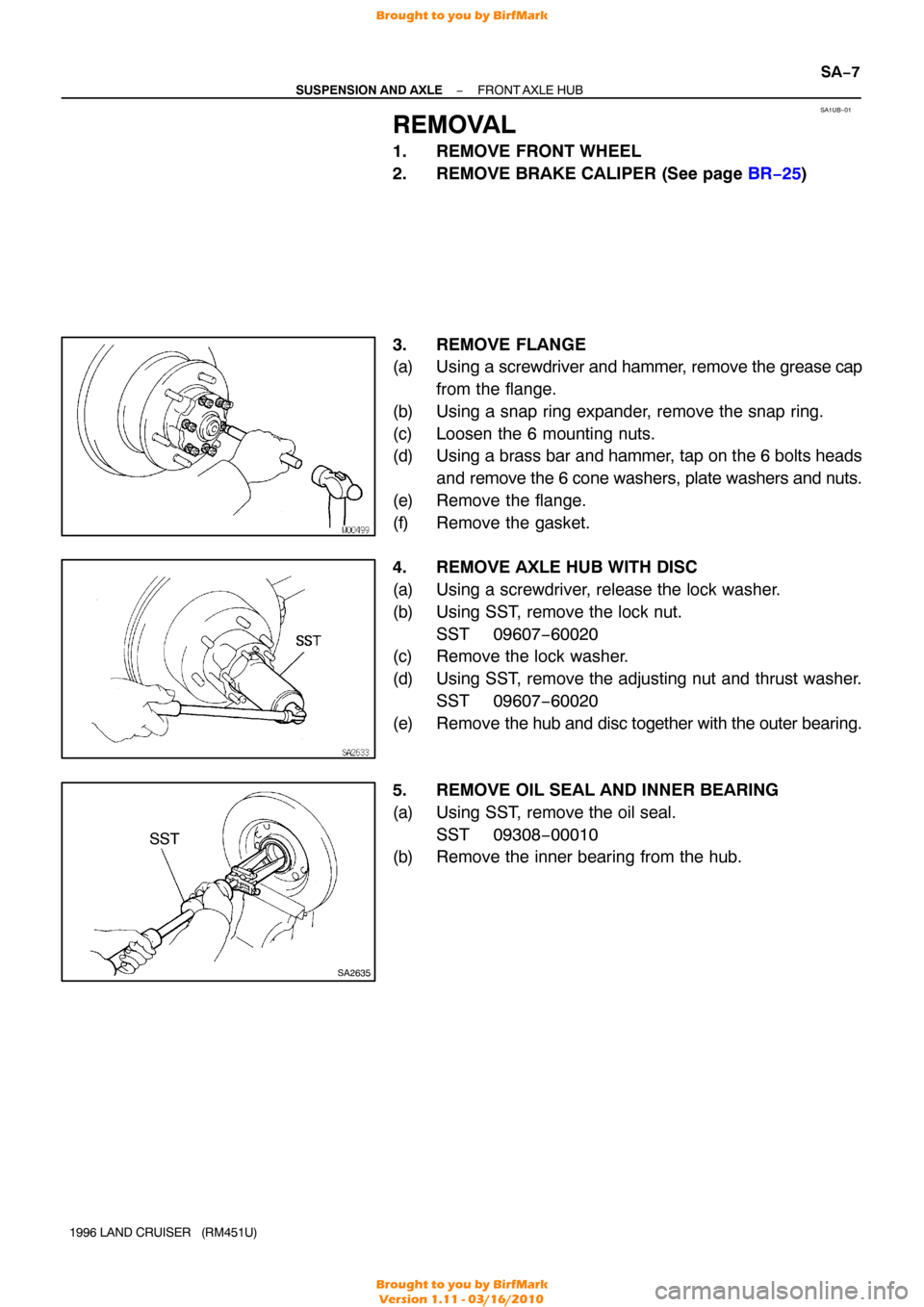
REMOVAL
1. REMOVE FRONT WHEEL
2. REMOVE BRAKE CALIPER (See page BR−25 )
3. REMOVE FLANGE
(a) Using a screwdriver and hammer, remove the grease cap
from the flange.
(b) Using a snap ring expander, remove the snap ring.
(c) Loosen the 6 mounting nuts.
(d) Using a brass bar and hammer, tap on the 6 bolts heads and remove the 6 cone washers, plate washers and nuts.
(e) Remove the flange.
(f) Remove the gasket.
4. REMOVE AXLE HUB WITH DISC
(a) Using a screwdriver, release the lock washer.
(b) Using SST, remove the lock nut. SST 09607−60020
(c) Remove the lock washer.
(d) Using SST, remove the adjusting nut and thrust washer.
SST 09607−60020
(e) Remove the hub and disc together with the outer bearing.
5. REMOVE OIL SEAL AND INNER BEARING
(a) Using SST, remove the oil seal. SST 09308−00010
(b) Remove the inner bearing from the hub.
Brought to you by BirfMark
Brought to you by BirfMark
Version 1.11 - 03/16/2010
Page 1073 of 1399
R08416
SA−10
−
SUSPENSION AND AXLE FRONT AXLE HUB
1996 LAND CRUISER (RM451U)
(e) Secure the lock nut by bending one of the lock washer
teeth inward and the other lock washer teeth outward.
7. INSTALL FLANGE
(a) Place a new gasket in position on the axle hub.
(b) Apply MP grease to the inner flange splines.
(c) Install the flange to the axle hub.
(d) Install the 6 cone washers, plate washers and nuts.
(e) Torque the 6 nuts.
Torque: 35 N·m (360 kgf·cm, 26 ft·lbf)
(f) Install the bolt in the axle shaft and pull it out.
(g) Using a snap ring expander, install a new snap ring.
(h) Remove the bolt.
(i) Coat inside of the cap with MP grease.
(j) Install the cap to the flange.
8. INSTALL BRAKE CALIPER (See page BR−29 )
9. INSTALL FRONT WHEEL Torque:
Steel wheel: 147 N·m (1,500 kgf·cm, 109 ft·lbf)
Alumimum wheel: 103 N·m (1,050 kgf·cm, 76 ft·lbf)
10. BLEED BRAKE LINE
Brought to you by BirfMark
Brought to you by BirfMark
Version 1.11 - 03/16/2010
Page 1130 of 1399
SA1V9−01
−
SUSPENSION AND AXLE REAR AXLE HUB
SA−67
1996 LAND CRUISER (RM451U)
REMOVAL
1. REMOVE REAR WHEEL
2. REMOVE REAR AXLE SHAFT (See page SA−63 )
3. REMOVE BRAKE CALIPER AND DISC (See page BR−34 )
4. DISCONNECT ABS SPEED SENSOR
Remove the bolt and disconnect the ABS speed sensor.
5. REMOVE REAR AXLE BEARING LOCK NUT
(a) Remove the 2 screws from the lock nut.
(b) Using SST, remove the lock nut. SST 09509−25011
6. REMOVE REAR AXLE HUB
(a) Pull out the axle hub, remove the lock nut plate and outer
bearing.
(b) Remove the axle hub.
Brought to you by BirfMark
Brought to you by BirfMark
Version 1.11 - 03/16/2010
Page 1132 of 1399

SA1VB−01
R08001
Lock Nut Mark
Axle Housing
Mark
−
SUSPENSION AND AXLE REAR AXLE HUB
SA−69
1996 LAND CRUISER (RM451U)
INSTALLATION
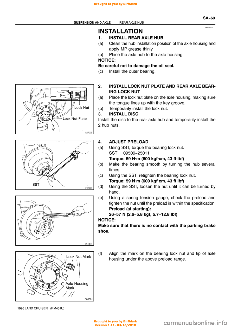
1. INSTALL REAR AXLE HUB
(a) Clean the hub installation position of the axle housing and
apply MP grease thinly.
(b) Place the axle hub to the axle housing.
NOTICE:
Be careful not to damage the oil seal.
(c) Install the outer bearing.
2. INSTALL LOCK NUT PLATE AND REAR AXLE BEAR- ING LOCK NUT
(a) Place the lock nut plate on the axle housing, making sure
the tongue lines up with the key groove.
(b) Temporarily install the lock nut.
3. INSTALL DISC
Install the disc to the rear axle hub and temporarily install the
2 hub nuts.
4. ADJUST PRELOAD
(a) Using SST, torque the bearing lock nut.SST 09509−25011
Torque: 59 N·m (600 kgf·cm, 43 ft·lbf)
(b) Make the bearing smooth by turning the hub several
times.
(c) Using the SST, retighten the bearing lock nut. Torque: 59 N·m (600 kgf·cm, 43 ft·lbf)
(d) Using the SST, loosen the nut until it can be turned by
hand.
(e) Using a spring tension gauge, check the preload and tighten the nut until the preload is within the specification.
Preload (at starting):
26−57 N (2.6−5.8 kgf, 5.7−12.8 lbf)
NOTICE:
Make sure that there is no contact with the parking brake
shoe.
(f) Align the mark on the bearing lock nut and tip of axle housing under the above preload range.
Brought to you by BirfMark
Brought to you by BirfMark
Version 1.11 - 03/16/2010