Page 1192 of 1399

(d) Observe the following precautio")
P09286
New O−ring
Grommet Injector
Delivery Pipe WRONG
CORRECT
P09401
Fuel Return Hose
SF−4
−
SFI SFI SYSTEM
632
Author�: Date�:
1996 LAND CRUISER (RM451U)
(d) Observe the following precautions when removing and
installing the injectors.
(1) Never reuse the O −ring.
(2) When placing a new O −ring on the injector, take
care not to damage it in any way.
(3) Coat a new O −ring with spindle oil or gasoline be-
fore installing −never use engine, gear or brake oil.
(e) Install the injector to the delivery pipe and intake manifold
as shown in the illustration.
(f) Check that there are no fuel leaks after doing mainte- nance anywhere on the fuel system.
(1) Remove the fuse cover on the instrument panel.
(2) Connect the TOYOTA hand− held tester to the
DLC3.
(3) Turn the ignition switch ON and TOYOTA hand −
held tester main switch ON.
NOTICE:
Do not start the engine. (4) Select the active test mode on the TOYOTA hand−held tester.
(5) Please refer to the TOYOTA hand −held tester oper-
ator ’s manual for further details.
If you have no T OYOTA hand−held tester, connect the positive
(+) and negative ( −) leads from the battery to the fuel pump con-
nector (See page SF−14 ).
(6) Pinch the fuel return hose. The pressure in the high
pressure line will rise to approx. 392 kPa (4 kgf/cm
2,
57 psi). In this state, check to see that there are no
leaks from any part of the fuel system.
NOTICE:
Always pinch the hose. Avoid bending as it may cause the
hose to crack.
(7) Turn the ignition switch to LOCK.
(8) Disconnect the TOYOTA hand −held tester from the
DLC3.
Brought to you by BirfMark
Brought to you by BirfMark
Version 1.11 - 03/16/2010
Page 1199 of 1399

INSPECTION
1. REMOVE SECOND SEATS
2. REMOVE SCUFF PLATE
3. REMOVE SIDE GARNISH
4. REMOVE STEP PLATE
5. DISCONNECT FLOOR MATS
6. REMOVE")
SF1EG−02
SF−14
−
SFI FUEL PUMP
1996 LAND CRUISER (RM451U)
INSPECTION
1. REMOVE SECOND SEATS
2. REMOVE SCUFF PLATE
3. REMOVE SIDE GARNISH
4. REMOVE STEP PLATE
5. DISCONNECT FLOOR MATS
6. REMOVE FLOOR SERVICE HOLE COVER
Remove the 3 screws and service hole cover.
7. DISCONNECT FUEL PUMP AND SENDER GAUGE CONNECTOR
8. INSPECT FUEL PUMP RESISTANCE
Using an ohmmeter, measure the resistance between the ter-
minals 5 and 6. Resistance: 0.2 − 3.0 Ω at 20°C (68°F)
If the resistance is not as specified, replace the fuel pump.
9. INSPECT FUEL PUMP OPERATION
Connect the positive (+) lead from the battery to terminal 6 of
the connector, and the negative ( −) lead to terminal 5. Check
that the fuel pump operates.
NOTICE:
�These tests must be performed quickly (within 10 se-
conds) to prevent the coil from burning out.
�Keep the fuel pump as far away from the battery as
possible.
�Always perform switching at the battery side.
If operation is not as specified, replace the fuel pump.
10. RECONNECT FUEL PUMP AND SENDER GAUGE CONNECTOR
Brought to you by BirfMark
Brought to you by BirfMark
Version 1.11 - 03/16/2010
Page 1216 of 1399

(f) Install the grommet and O−ring to the injector.
(g) Connect SST (union and hose) to the injector, and hold
the injector and u")
FI4848
FI4849
SF−30
−
SFI INJECTOR
1996 LAND CRUISER (RM451U)
(f) Install the grommet and O−ring to the injector.
(g) Connect SST (union and hose) to the injector, and hold
the injector and union with SST (clamp).
SST 09268−41046
(h) Put the injector into the graduated cylinder.
HINT:
Install a suitable vinyl hose onto the injector to prevent gasoline
from splashing out.
(i) Remove the fuse cover on the instrument panel.
(j) Connect the TOYOTA hand−held tester to the DLC3.
(k) Turn the ignition switch ON and TOYOTA hand−held tes-
ter main switch ON.
NOTICE:
Do not start the engine.
(l) Select the active test mode on the TOYOTA hand −held
tester.
(m) Please refer to the TOYOTA hand −held tester operator’s
manual for further details.
(n) If you have no TOYOTA hand−held tester, connect the positive (+) and negative (−) leads from the battery to the
fuel pump connector (See page SF−14)
(o) Connect SST (wire) to the injector and battery for 15 se- conds, and measure the injection volume with a gra-
duated cylinder. Test each injector 2 or 3 times.
SST 09842−30070
Volume:
69 − 88 cm
3 (4.2 − 5.4 cu in.) per 15 seconds
Difference between each injector:
5 cm
3 (0.3 cu in.) or less
If the injection volume is not as specified, replace the injector.
2. INSPECT LEAKAGE
(a) In the condition above, disconnect the test probes of SST (wire) from the battery and check the fuel leakage from
the injector.
SST 09842−30070
Fuel drop: One drop or less per minute
(b) Turn the ignition switch to LOCK.
(c) Disconnect the negative ( −) terminal cable from the bat-
tery.
Brought to you by BirfMark
Brought to you by BirfMark
Version 1.11 - 03/16/2010
Page 1238 of 1399
SF1F2−01
SF−52
−
SFI IDLE AIR CONTROL (IAC) VALVE
1996 LAND CRUISER (RM451U)
INSPECTION
INSPECT IDLE AIR CONTROL VALVE OPERATION
(a) Apply battery voltage to terminals B1 and B2, and while repeatedly grounding S1 −S2−S3−S4−S1 in sequence,
and check that the valve moves toward the closed posi-
tion.
(b) Apply battery voltage to terminals B1 and B2, and while repeatedly grounding S4 −S3−S2−S1−S4 in sequence,
and check that the valve moves toward the open position.
If operation is not as specified, replace the IAC valve.
Brought to you by BirfMark
Brought to you by BirfMark
Version 1.11 - 03/16/2010
Page 1240 of 1399
SF06G−11
P05668
OhmmeterContinuity
No Continuity Ohmmeter
1
2
43
P05667
Ohmmeter Continuity
Battery
1
2
4 3
SF−54
−
SFI EFI MAIN RELAY
682
Author�: Date�:
1996 LAND CRUISER (RM451U)
EFI MAIN RELAY
INSPECTION
1. REMOVE EFI MAIN RELAY
LOCATION: In the engine compartment relay box.
2. INSPECT EFI MAIN RELAY CONTINUITY
(a) Using an ohmmeter, check that there is continuity be-
tween terminals 1 and 3.
(b) Check that there is no continuity between terminals 2 and
4.
If continuity is not as specified, replace the relay.
3. INSPECT EFI MAIN RELAY OPERATION
(a) Apply battery voltage across terminals 1 and 3.
(b) Using an ohmmeter, check that there is continuity be-
tween terminals 2 and 4.
If operation is not as specified, replace the relay.
4. REINSTALL EFI MAIN RELAY
Brought to you by BirfMark
Brought to you by BirfMark
Version 1.11 - 03/16/2010
Page 1242 of 1399
SF1F5−01
P05668
OhmmeterContinuity
Ohmmeter
No Continuity
1
2
43
P05667
Ohmmeter 1
2
3
4 Battery
SF−56
−
SFI CIRCUIT OPENING RELAY
1996 LAND CRUISER (RM451U)
INSPECTION
1. REMOVE CIRCUIT OPENING RELAY
2. INSPECT CIRCUIT OPENING RELAY CONTINUITY
(a) Using an ohmmeter, check that there is continuity be- tween terminals 1 and 3.
(b) Check that there is no continuity between terminals 2 and
4.
If continuity is not as specified, replace the relay.
3. INSPECT CIRCUIT OPENING RELAY OPERATION
(a) Apply battery voltage across terminals 1 and 3.
(b) Using an ohmmeter, check that there is continuity be- tween terminals 2 and 4.
If operation is not as specified, replace the relay.
4. REINSTALL CIRCUIT OPENING RELAY
Brought to you by BirfMark
Brought to you by BirfMark
Version 1.11 - 03/16/2010
Page 1243 of 1399

SF1F7−01
P09134
OhmmeterContinuity
Ohmmeter Ohmmeter
Continuity
No Continuity FP
PR
FPR
+B1
+B2
P09135
Ohmmeter
No
Continuity
Battery
Ohmmeter
Continuity +B1
+B2 FP
PR
FPR
−
SFI FUEL PUMP RELAY
SF−57
685
Author�: Date�:
1996 LAND CRUISER (RM451U)
FUEL PUMP RELAY
INSPECTION
1. REMOVE FUEL PUMP RELAY
(a) Disconnect the fuel pump relay connector.
(b) Remove the bolt and fuel pump relay.
2. INSPECT FUEL PUMP RELAY CONTINUITY
(a) Using an ohmmeter, check that there is continuity be-
tween terminals +B1 and FPR.
(b) Check that there is continuity between terminals +B2 and
FP.
(c) Check that there is no continuity between terminals +B2
and PR.
If continuity is not as specified, replace the relay.
3. INSPECT FUEL PUMP RELAY OPERATION
(a) Apply battery voltage across terminals +B1 and FPR.
(b) Using an ohmmeter, check that there is no continuity be- tween the +B2 and FP.
(c) Check that there is continuity between terminals +B2 and
PR.
If operation is not as specified, replace the relay.
4. REINSTALL FUEL PUMP RELAY
Brought to you by BirfMark
Brought to you by BirfMark
Version 1.11 - 03/16/2010
Page 1245 of 1399
SF1F9−01
−
SFI VSV FOR FUEL PRESSURE CONTROL
SF−59
687
Author�: Date�:
1996 LAND CRUISER (RM451U)
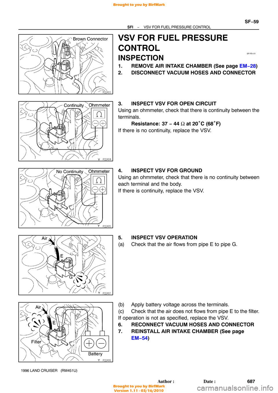
VSV FOR FUEL PRESSURE
CONTROL
INSPECTION
1. REMOVE AIR INTAKE CHAMBER (See page EM−28 )
2. DISCONNECT VACUUM HOSES AND CONNECTOR
3. INSPECT VSV FOR OPEN CIRCUIT
Using an ohmmeter, check that there is continuity between the
terminals. Resistance: 37 − 44 Ω at 20° C (68°F)
If there is no continuity, replace the VSV.
4. INSPECT VSV FOR GROUND
Using an ohmmeter, check that there is no continuity between
each terminal and the body.
If there is continuity, replace the VSV.
5. INSPECT VSV OPERATION
(a) Check that the air flows from pipe E to pipe G.
(b) Apply battery voltage across the terminals.
(c) Check that the air does not flows from pipe E to the filter.
If operation is not as specified, replace the VSV.
6. RECONNECT VACUUM HOSES AND CONNECTOR
7. REINSTALL AIR INTAKE CHAMBER (See page EM−54 )
Brought to you by BirfMark
Brought to you by BirfMark
Version 1.11 - 03/16/2010
 VALVE
1996 LAND CRUISER (RM451U)
INSPECTION
INSPECT IDLE AIR CONTROL VALVE OPERATION
(a) Apply battery voltage to terminals B1 and B2, and while rep")


INSPECTION
1. REMOVE CIRCUIT OPENI")