Page 32 of 1399

Z17004
Fig. 1
OPENECU
2
Sensor
22 2 1
111 AB
C
Z17005
Fig. 2
ECU
Sensor 21 A
B
C
1
1
22
B04722
Fig. 3
ECU
Sensor
21 A
C 1
1
221
2
1 B1
B2
IN−30−
INTRODUCTION HOW TO TROUBLESHOOT ECU CONTROLLED
SYSTEMS
1996 LAND CRUISER (RM451U)
(d) Prepare a test male terminal and insert it in the female ter-
minal, then pull it out.
NOTICE:
When testing a gold −plated female terminal, always use a
gold −plated male terminal.
HINT:
When the test terminal is pulled out more easily than others,
there may be poor contact in that section.
6. CHECK OPEN CIRCUIT
For the open circuit in the wire harness in Fig. 1, perform ”(a)
Continuity Check” or ”(b) Voltage Check” to locate the section.
(a) Check the continuity. (1) Disconnect connectors ”A” and ”C” and measurethe resistance between them.
In the case of Fig. 2:
Between terminal 1 of connector ”A” and terminal 1
of connector ”C” → No continuity (open)
Between terminal 2 of connector ”A” and terminal 2
of connector ”C” → Continuity
Therefore, it is found out that there is an open circuit
between terminal 1 of connector ”A” and terminal 1
of connector ”C”.
(2) Disconnect connector ”B” and measure the resis- tance between the connectors.
In the case of Fig. 3:
Between terminal 1 of connector ”A” and terminal 1
of connector ”B1” → Continuity
Between terminal 1 of connector ”B2” and terminal
1 of connector ”C” → No continuity (open)
Therefore, it is found out that there is an open circuit
between terminal 1 of connector ”B2” and terminal
1 of connector ”C”.
BE4063
DO
Brought to you by BirfMark
Brought to you by BirfMark
Version 1.11 - 03/16/2010
Page 33 of 1399

Z17007
Fig. 4Sensor 21 A
C
1
1
22B5V
5V
5V
0V
Z17008
Fig. 5
2
1 A
C
1
1
2 2
BSHORT
Z17009
Fig. 6
21 A
C
1
1
22
BSensor ECU
−
INTRODUCTION HOW TO TROUBLESHOOT ECU CONTROLLED
SYSTEMSIN−31
1996 LAND CRUISER (RM451U)
(b) Check the voltage.
In a circuit in which voltage is applied (to the ECU connec-
tor terminal), an open circuit can be checked for by con-
ducting a voltage check.As shown in Fig. 4, with each connector still con-
nected, measure the voltage between body ground
and terminal 1 of connector ”A” at the ECU 5V out-
put terminal, terminal 1 of connector ”B”, and termi-
nal 1 of connector ”C”, in that order.
If the results are:
5V: Between Terminal 1 of connector ”A” and Body Ground
5V: Between Terminal 1 of connector ”B” and Body Ground
0V: Between Terminal 1 of connector ”C” and Body Ground
Then it is found out that there is an open circuit in the wire har-
ness between terminal 1 of ”B” and terminal 1 of ”C”.
7. CHECK SHORT CIRCUIT
If the wire harness is ground shorted as in Fig. 5, locate the sec-
tion by conducting a ”continuity check with ground”.
Check the continuity with ground. (1) Disconnect connectors ”A” and ”C” and measurethe resistance between terminal 1 and 2 of connec-
tor ”A” and body ground.
In the case of Fig. 6:
Between terminal 1 of connector ”A” and body
ground → Continuity (short)
Between terminal 2 of connector ”A” and body
ground → No continuity
Therefore, it is found out that there is a short circuit
between terminal 1 of connector ”A” and terminal 1
of connector ”C”.
BE4066
BE4067
BE4068
Brought to you by BirfMark
Brought to you by BirfMark
Version 1.11 - 03/16/2010
Page 34 of 1399

Z17808
Fig. 7Sensor 21 A
B1
C
1
1
221 2
B2
ECU
IN0383
Example
Ground
IN0384
Ground
Ground
ECU Side
W/H Side
IN−32
−
INTRODUCTION HOW TO TROUBLESHOOT ECU CONTROLLED
SYSTEMS
1996 LAND CRUISER (RM451U)
(2) Disconnect connector ”B” and measure the resis-
tance between terminal 1 of connector ”A” and body
ground, and terminal 1 of connector ”B2” and body
ground.
In the case of Fig. 7:
Between terminal 1 of connector ”A” and body
ground → No continuity
Between terminal 1 of connector ”B2” and body
ground → Continuity (short)
Therefore, it is found out that there is a short circuit
between terminal 1 of connector ”B2” and terminal
1 of connector ”C”.
8. CHECK AND REPLACE ECU
First check the ECU ground circuit. If it is faulty, repair it. If it is
normal, the ECU could be faulty, so replace the ECU with a nor-
mal functioning one and check that the symptoms appear.
(1) Measure the resistance between the ECU groundterminal and the body ground.
Resistance: 1 Ω or less
(2) Disconnect the ECU connector, check the ground terminals on the ECU side and the wire harness
side for bend and check the contact pressure.
o
D~~~D~~~
Brought to you by BirfMark
Brought to you by BirfMark
Version 1.11 - 03/16/2010
Page 78 of 1399

DISASSEMBLY
1. RUN ENGINE AT IDLE SPEED WITH A/C SWITCH ON
FOR 10 M")
AC2R7−04
AC0943
SST
AC0944
SST
AC0945
SST
−
AIR CONDITIONING COMPRESSOR AND MAGNETIC CLUTCH
AC−35
1996 LAND CRUISER (RM451U)
DISASSEMBLY
1. RUN ENGINE AT IDLE SPEED WITH A/C SWITCH ON
FOR 10 MINUTES
2. STOP ENGINE
3. DISCONNECT NEGATIVE ( −) TERMINAL CABLE
FROM BATTERY
4. DISCHARGE REFRIGERANT FROM REFRIGERA TION
SYSTEM
5. DISCONNECT DISCHARGE AND SUCTION HOSES
Remove the 2 bolts and disconnect the both hoses.
NOTICE:
Cap the open fittings immediately to keep the moisture or
dirt out of the system.
6. REMOVE ENGINE UNDER COVER
7. REMOVE DRIVE BELT (See page AC−16)
8. REMOVE COMPRESSOR
(a) Disconnect the connector.
(b) Remove the 4 bolts and pull the compressor upward.
9. REMOVE COMPRESSOR (See page AC−35 )
10. REMOVE PRESSURE PLATE
(a) Using SST and a socket wrench, remove the shaft bolt. Torque: 13.2 N·m (135 kgf·cm, 9 ft·lbf)
SST 07112 −76060
(b) Install a SST on the pressure plate. SST 07112 −66040
(c) Using SST and a socket wrench, remove the pressure plate.
SST 07112 −76060
Brought to you by BirfMark
Brought to you by BirfMark
Version 1.11 - 03/16/2010
Page 81 of 1399

REASSEMBLY
1. INSTALL COMPRESSOR
(a) Install the compressor with the 4 bolts. Torque: 25 N·m")
AC2R8−01
N04963
AC−38
−
AIR CONDITIONING COMPRESSOR AND MAGNETIC CLUTCH
1996 LAND CRUISER (RM451U)
REASSEMBLY
1. INSTALL COMPRESSOR
(a) Install the compressor with the 4 bolts. Torque: 25 N·m (250 kgf·cm, 18 ft·lbf)
(b) Connect the connector.
2. CONNECT DISCHARGE AND SUCTION HOSES Torque: 10 N·m (100 kgf·cm, 7 ft·lbf)
NOTICE:
Hoses should be connected immediately after the caps
have been removed.
HINT:
Lubricate 2 new O −rings with compressor oil and install the
hoses.
3. INSTALL AND INSPECT DRIVE BELT (See page AC−17 )
4. INSTALL ENGINE UNDER COVER
5. CONNECT NEGATIVE ( −) TERMINAL CABLE TO BAT-
TERY
6. EVACUATE AIR FROM REFRIGERATION SYSTEM
7. CHARGE SYSTEM WITH REFRIGERANT AND IN- SPECT FOR LEAKAGE OF REFRIGERANT
Specified amount:
850 ± 50 g (29.98 ± 1.76 oz.)
Using a gas leak detector, check for leakage of refrigerant.
If there is leakage, check the tightening torque at the joints.
8. INSPECT A/C OPERATION
Reassembly is in the reverse order of disassembly (See
page AC−35 ).
9. CHECK CLEARANCE OF MAGNETIC CLUTCH
(a) Set the dial indicator to the pressure plate of the magnetic
clutch.
(b) Connect the magnetic clutch lead wire to the positive (+) terminal of the battery.
(c) Check the clearance between the pressure plate and ro- tor when connecting the negative ( −) terminal to the bat-
tery.
Standard clearance:
0.5 ± 0.15 mm (0.020 ± 0.0059 in.)
If the clearance is not within the standard clearance, adjust the
clearance using shims to obtain the standard clearance. Shim Thickness:
0.1 mm (0.004 in.)
0.3 mm (0.012 in.)
0.5 mm (0.020 in.)
Brought to you by BirfMark
Brought to you by BirfMark
Version 1.11 - 03/16/2010
Page 95 of 1399
AC2RY−01
AC2227
AC−52
−
AIR CONDITIONING FRONT BLOWER MOTOR
1996 LAND CRUISER (RM451U)
INSPECTION
INSPECT BLOWER MOTOR OPERATION
Connect the positive (+) lead from the battery to terminal 2 and
the negative (− ) lead to terminal 1, then check that the motor op-
eration is smooth.
If operation is not as specified, replace the blower motor.
Brought to you by BirfMark
Brought to you by BirfMark
Version 1.11 - 03/16/2010
Page 98 of 1399
AC2S1−02
12
−
AIR CONDITIONING REAR BLOWER MOTOR
AC−55
1996 LAND CRUISER (RM451U)
INSPECTION
INSPECT BLOWER MOTOR OPERATION
Connect the positive (+) lead from the battery to terminal 1 and
the negative (− ) lead to terminal 2, then check that the motor op-
erations smoothly.
If operation is not as specified, replace the motor.
2
BE2611
Brought to you by BirfMark
Brought to you by BirfMark
Version 1.11 - 03/16/2010
Page 100 of 1399
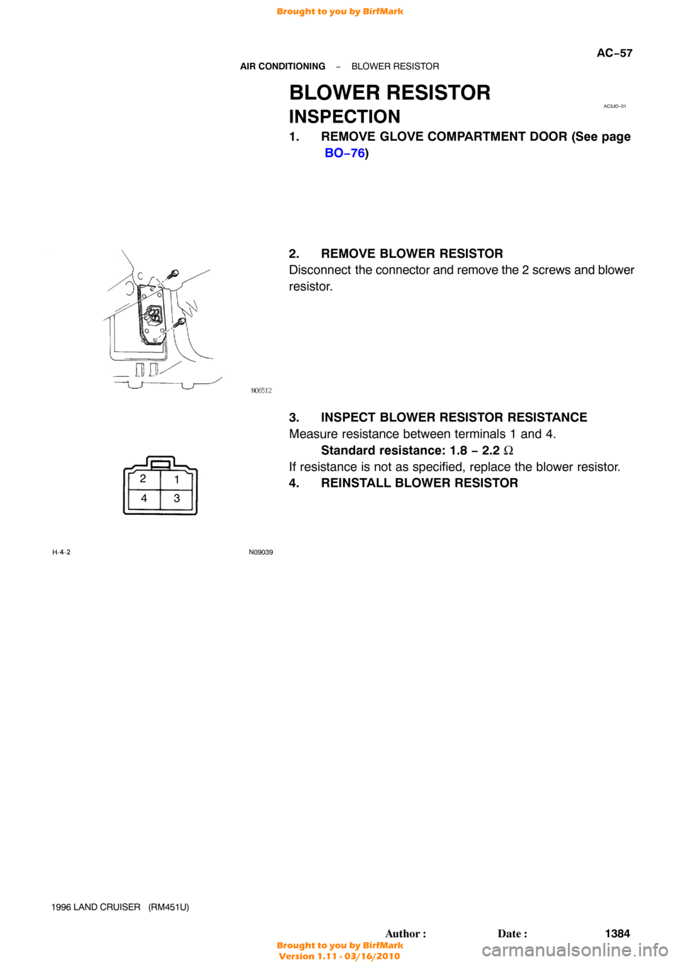
AC3JO−01
N09039
1
2
34
−
AIR CONDITIONING BLOWER RESISTOR
AC−57
1384
Author�: Date�:
1996 LAND CRUISER (RM451U)
BLOWER RESISTOR
INSPECTION
1. REMOVE GLOVE COMPARTMENT DOOR (See page
BO−76 )
2. REMOVE BLOWER RESISTOR
Disconnect the connector and remove the 2 screws and blower
resistor.
3. INSPECT BLOWER RESISTOR RESISTANCE
Measure resistance between terminals 1 and 4. Standard resistance: 1.8 − 2.2 Ω
If resistance is not as specified, replace the blower resistor.
4. REINSTALL BLOWER RESISTOR
H-4-2
ru;S12
Brought to you by BirfMark
Brought to you by BirfMark
Version 1.11 - 03/16/2010

INSPECTION
INSPECT BLOWER MOTOR OPERATION
Connect the positive (+) lead from the battery to terminal 2")

INSPECTION
INSPECT BLOWER MOTOR OPERATION
Connect the positive (+) lead from the battery to terminal 1 and
th")