Page 1072 of 1399

INSTALLATION
1. PACK BEARINGS WITH MP GREASE
(a) Place MP grease on the palm of your hand")
SA1UD−01
SA2636
Grease
R04134
SST
−
SUSPENSION AND AXLE FRONT AXLE HUB
SA−9
1996 LAND CRUISER (RM451U)
INSTALLATION
1. PACK BEARINGS WITH MP GREASE
(a) Place MP grease on the palm of your hand.
(b) Pack grease into the bearing until the grease oozes out
from the other side.
(c) Do the same around the bearing circumference.
2. COAT INSIDE OF HUB WITH MP GREASE
3. INSTALL INNER BEARING AND OIL SEAL
(a) Place the inner bearing into the hub.
(b) Using SST, install a new oil seal into the hub. SST 09950−60020 (09951 −00910),
09950 −70010 (09951 −07150)
(c) Coat the oil seal lip with MP grease.
4. INSTALL AXLE HUB WITH DISC TO SPINDLE
(a) Place the axle hub with disc to the spindle.
(b) Install the outer bearing.
(c) Install the thrust washer.
5. ADJUST PRELOAD
(a) Using SST, torque the adjusting nut.
SST 09607−60020
Torque: 59 N·m (600 kgf·cm, 43 ft·lbf)
(b) Turn the hub right and left 2 or 3 times.
(c) Using SST, torque the adjusting nut.
SST 09607−60020
Torque: 59 N·m (600 kgf·cm, 43 ft·lbf)
(d) Loosen the nut until it can be turned by hand.
(e) Using SST, torque the adjusting nut again.
SST 09607−60020
Torque: 5.4 N·m (55 kgf·cm, 48 in.·lbf)
NOTICE:
Check that the bearing has no play.
(f) Using a spring tension gauge, measure the preload.
Preload (at starting):
28 − 56 N (2.9 − 5.7 kgf, 6.4 − 12.6 lbf)
6. INSTALL LOCK WASHER AND LOCK NUT
(a) Install a new lock washer and lock nut.
(b) Using SST, torque the lock nut. SST 09607−60020
Torque: 64 N·m (650 kgf·cm, 47 ft·lbf)
(c) Check that axle hub turns smoothly and that the bearing has no play.
(d) Using a spring tension gauge, check the preload. Preload (at starting):
28−56 N (2.9−5.7 kgf, 6.4−12.6 lbf)
If it is not within the specification, adjust it with the adjusting nut
after removing the lock washer and lock nut.
Brought to you by BirfMark
Brought to you by BirfMark
Version 1.11 - 03/16/2010
Page 1073 of 1399
R08416
SA−10
−
SUSPENSION AND AXLE FRONT AXLE HUB
1996 LAND CRUISER (RM451U)
(e) Secure the lock nut by bending one of the lock washer
teeth inward and the other lock washer teeth outward.
7. INSTALL FLANGE
(a) Place a new gasket in position on the axle hub.
(b) Apply MP grease to the inner flange splines.
(c) Install the flange to the axle hub.
(d) Install the 6 cone washers, plate washers and nuts.
(e) Torque the 6 nuts.
Torque: 35 N·m (360 kgf·cm, 26 ft·lbf)
(f) Install the bolt in the axle shaft and pull it out.
(g) Using a snap ring expander, install a new snap ring.
(h) Remove the bolt.
(i) Coat inside of the cap with MP grease.
(j) Install the cap to the flange.
8. INSTALL BRAKE CALIPER (See page BR−29 )
9. INSTALL FRONT WHEEL Torque:
Steel wheel: 147 N·m (1,500 kgf·cm, 109 ft·lbf)
Alumimum wheel: 103 N·m (1,050 kgf·cm, 76 ft·lbf)
10. BLEED BRAKE LINE
Brought to you by BirfMark
Brought to you by BirfMark
Version 1.11 - 03/16/2010
Page 1074 of 1399
SA1UE−01
−
SUSPENSION AND AXLE FRONT WHEEL HUB BOLT
SA−11
868
Author�: Date�:
1996 LAND CRUISER (RM451U)
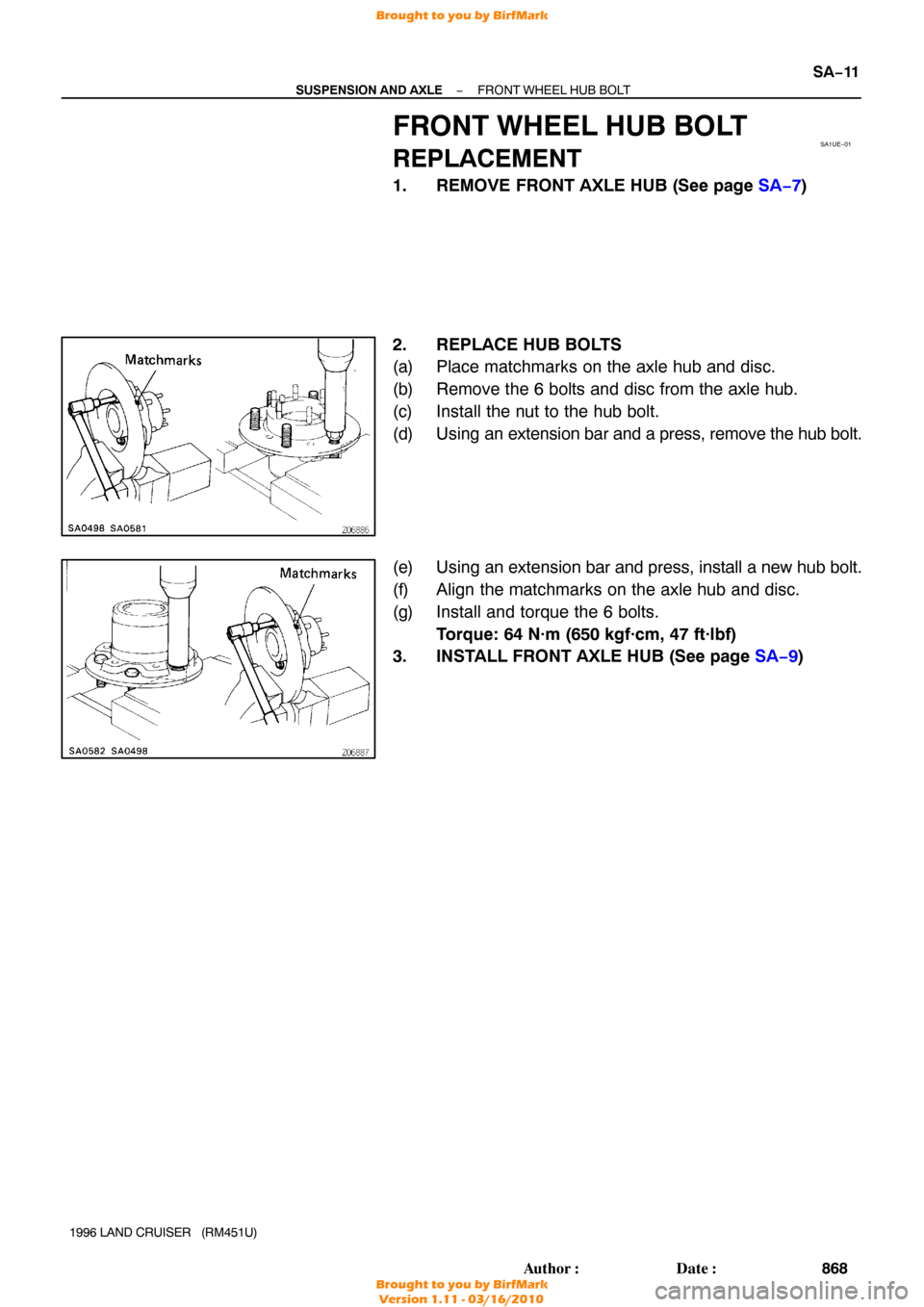
FRONT WHEEL HUB BOLT
REPLACEMENT
1. REMOVE FRONT AXLE HUB (See page SA−7 )
2. REPLACE HUB BOLTS
(a) Place matchmarks on the axle hub and disc.
(b) Remove the 6 bolts and disc from the axle hub.
(c) Install the nut to the hub bolt.
(d) Using an extension bar and a press, remove the hub bolt.
(e) Using an extension bar and press, install a new hub bolt.
(f) Align the matchmarks on the axle hub and disc.
(g) Install and torque the 6 bolts. Torque: 64 N·m (650 kgf·cm, 47 ft·lbf)
3. INSTALL FRONT AXLE HUB (See page SA−9)
Brought to you by BirfMark
Brought to you by BirfMark
Version 1.11 - 03/16/2010
Page 1076 of 1399

REMOVAL
1. REMOVE FRONT AXLE HUB (See page SA−7 )
2. REMOVE AB")
SA1UG−01
W00495
SA2644
SST
R08383
R13137
−
SUSPENSION AND AXLE STEERING KNUCKLE AND AXLE SHAFT
SA−13
1996 LAND CRUISER (RM451U)
REMOVAL
1. REMOVE FRONT AXLE HUB (See page SA−7 )
2. REMOVE ABS SPEED SENSOR
Remove the 2 bolts and disconnect the speed sensor from the
steering knuckle.
3. REMOVE DUST SEAL AND DUST COVER
Remove the 8 bolts, dust seal, dust cover and gasket.
4. REMOVE KNUCKLE SPINDLE
(a) Using a brass bar and hammer, tap the knuckle spindle of the steering knuckle.
(b) Remove the knuckle spindle and gasket.
5. REMOVE AXLE SHAFT
Position one flat part of the outer shaft upward and remove the
axle shaft.
6. DISCONNECT TIE ROD FROM KNUCKLE ARM
(a) Remove the cotter pin and nut.
(b) Using SST, disconnect the tie rod from the knuckle arm. SST 09611 −22012
7. REMOVE OIL SEAL SET
(a) Remove the 6 bolts from the end retainer.
(b) Remove these parts from the steering knuckle:
�Oil seal end retainer
�Felt dust seal
�Rubber seal
�Steel ring
8. REMOVE KNUCKLE ARM AND BEARING CAP
(a) Remove the 2 bolts and plate washers from the bearing cap.
(b) Remove the 4 nuts from the knuckle arm.
(c) Using a brass bar and hammer, tap on the 4 bolts heads and remove the 4 cone washers.
Brought to you by BirfMark
Brought to you by BirfMark
Version 1.11 - 03/16/2010
Page 1082 of 1399
−
SUSPENSION AND AXLE STEERING KNUCKLE AND AXLE SHAFT
SA−19
1996 LAND CRUISER (RM451U)
(c) Torque the 8 bolts.
Torque: 47 N·m (475 kgf·cm, 34 ft·lbf)
13. CONNECT ABS SPEED SENSOR
Connect the speed sensor and 2 bolts to the steering knuckle.
Torque: 18 N·m (185 kgf·cm, 13 ft·lbf)
14. INSTALL AXLE HUB (See page SA−9)
15. CHECK FRONT WHEEL ALIGNMENT (See page SA−4 )
16. CHECK ABS SPEED SENSOR SIGNAL (See page DI−190 )
Brought to you by BirfMark
Brought to you by BirfMark
Version 1.11 - 03/16/2010
Page 1327 of 1399

Center differential side gear thrust washer thickness
1.70 mm (0.0669 in.)
1.85 mm (0.0728 in.)
2.00 mm (0.")
SS−26
−
SERVICE SPECIFICATIONS TRANSFER
149
Author�: Date�:
1996 LAND CRUISER (RM451U)
Center differential side gear thrust washer thickness
1.70 mm (0.0669 in.)
1.85 mm (0.0728 in.)
2.00 mm (0.0787 in.)
2.15 mm (0.0846 in.)
2.30 mm (0.0906 in.)
2.45 mm (0.0965 in.)
2.60 mm (0.1024 in.)
2.75 mm (0.1083 in.)
2.90 mm (0.1142 in.)
3.05 mm (0.1201 in.)
Front drive gear piece snap ring thickness
Mark A
B
C
D E
F
G H J
K
L2.00 mm (0.0787 in.)
2.10 mm (0.0827 in.)
2.20 mm (0.0866 in.)
2.30 mm (0.0906 in.)
2.40 mm (0.0945 in.)
2.50 mm (0.0984 in.)
2.60 mm (0.1024 in.)
2.70 mm (0.1063 in.)
2.80 mm (0.1102 in.)
1.80 mm (0.0709 in.)
1.90 mm (0.0748 in.)
Front extension housing ball bearing snap ring thickness Mark A
B1.7 mm (0.0669 in.)
1.8 mm (0.0709 in.)
Front output shaft hub snap ring thickness Mark A
B
C
D E1.8 mm (0.0709 in.)
1.9 mm (0.0748 in.)
2.0 mm (0.0787 in.)
2.1 mm (0.0827 in.)
2.2 mm (0.0866 in.)
Oil pump driven rotor body clearance STD
Max.0.08 − 0.17 mm (0.0031 − 0.0067 in.)
0.17 mm (0.0067 in.)
Oil pump driven rotor body tip clearance STD
Max.0.05 − 0.15 mm (0.0020 − 0.0059 in.)
0.15 mm (0.0059 in.)
Oil pump side clearance STD
Max.0.03 − 0.10 mm (0.0012 − 0.0039 in.)
0.10 mm (0.0039 in.)
Rear extension housing ball bearing snap ring thickness Mark A
B1.7 mm (0.0669 in.)
1.8 mm (0.0709 in.)
Rear output shaft ball bearing snap ring thickness Mark 1
2
3
41.95 mm (0.0768 in.)
2.05 mm (0.0807 in.)
2.15 mm (0.0847 in.)
2.25 mm (0.0886 in.)
Motor actuator
Terminal 2 − Terminal 3 STD resistance
Terminal 2 or 3 − Body ground STD resistance
0.3 − 100 Ω
More than 0.5 MΩ
Brought to you by BirfMark
Brought to you by BirfMark
Version 1.11 - 03/16/2010
Page 1331 of 1399

SUSPENSION AND AXLE
SERVICE DATA
Cold tire inflation
pressureTire size
P275/70R 16")
SS1EC−02
SS−30
−
SERVICE SPECIFICATIONS SUSPENSION AND AXLE
153
Author�: Date�:
1996 LAND CRUISER (RM451U)
SUSPENSION AND AXLE
SERVICE DATA
Cold tire inflation
pressureTire size
P275/70R 16
220 kPa (2.2 kgf/cm2, 32 psi)
Follow spring and
bumper stopper
clearanceFollow spring clearance (Front)
Bumper stopper clearance (Rear)36 mm (1.42 in.)
104 mm (4.09 in.)
Front wheel align-
mentCamber Left−right error1°00’ ± 45’
45’ or less
Caster Left−right error3°00’ ± 60’
45’ or less
Steering axis inclination13 °00’ ± 45’
To e −in (Total) Inspection STD
Adjustment STD0.2 ° ± 0.2° (2 ± 2 mm, 0.08 ± 0.08 in.)
0.2 ° ± 0.1° (2 ± 1 mm, 0.08 ± 0.04 in.)
Wheel angle (Max.) Inside wheel
Outside wheel32 °00’ − 35°00’
31 °00’
Tire and wheelTire runout
Wheel balance (Unbalance after adjustment)
Wheel bearing preload (at starting) Front
(Rotating load at hub bolt) Rear3.0 mm (0.118 in.) or less
13.0 g (0.029 lb) or less
28 − 56 N (2.9 − 5.7 kgf, 6.4 − 12.6 lbf)
26 − 57 N (2.6 − 5.8 kgf, 5.7 − 12.8 lbf)
Front axleSteering knuckle bearing preload
(Rotating load at knuckle end, before installing dust seal)
25 − 44 N (2.5 − 4.5 kgf, 5.5 − 9.9 lbf)
Front dif ferentialDrive pinion preload (at starting) New bearing
Reused bearing0.9 − 1.6 N·m (10 − 16 kgf·cm, 8.7 − 13.9 in.·lbf)
0.5 − 0.8 N·m (5 − 8 kgf·cm, 4.3 − 6.9 in.·lbf)
Total preload (at starting)Drive pinion preload plus
0.4 − 0.6 N·m (4 − 6 kgf·cm, 3.5 − 5.2 in.·lbf)
Drive pinion to ring gear backlash0.13 − 0.18 mm (0.0051 − 0.0071 in.)
Pinion gear to side gear backlash0.05 − 0.20 mm (0.0020 − 0.0079 in.)
Ring gear runout Max.0.10 mm (0.0039 in.)
Companion flange runoutMax. Radial
Lateral0.10 mm (0.0039 in.)
0.10 mm (0.0039 in.)
Oil seal drive in depth1.0 mm (0.039 in.)
Side gear thrust washer thickness w/o Differntial lock
w/ Differntial lock1.6 mm (0.063 in.)
1.7 mm (0.067 in.)
1.8 mm (0.071 in.)
0.9 mm (0.035 in.)
1.0 mm (0.039 in.)
1.1 mm (0.043 in.)
1.2 mm (0.047 in.)
1.3 mm (0.051 in.)
Brought to you by BirfMark
Brought to you by BirfMark
Version 1.11 - 03/16/2010
Page 1334 of 1399

TORQUE SPECIFICATION
Part tightenedN·mkgf·cmft·lbf
FRONT
Axle hub x Disc6465047
Axle hub bearing lock")
SS1ED−02
−
SERVICE SPECIFICATIONS SUSPENSION AND AXLE
SS−33
1996 LAND CRUISER (RM451U)
TORQUE SPECIFICATION
Part tightenedN·mkgf·cmft·lbf
FRONT
Axle hub x Disc6465047
Axle hub bearing lock nut6465047
Flange x Axle hub3536026
Brake caliper x Axle carrier1231,25090
Brake caliper x Flexible hose3031022
Steering knuckle x Knuckle arm9698071
Bearing cap x Steering knuckle9698071
Knuckle arm x Tie rod9192567
Steering knuckle x Knuckle spindle4747534
Oil seal end retainer x Knuckle arm5.45548 in.·lbf
ABS speed sensor set bolt x Steering knuckle1818513
Hub nut Steel wheel
Aluminum wheel147
1031,500
1,050109 76
Drain plug4950036
Filler plug4950036
Propeller shaft x Companion flange8890065
Side bearing cap x Differential carrier7880058
Ring gear x Differential case9798571
Drive pinion x Companion flange196 − 3432,000 − 3,500145 − 253
Differential LH case x RH case4748035
Differential lock shift retainer2424017
Differential lock screw plug2222016
Differential lock indicator switch4041030
Differential lock actuator2627020
Differential carrier x Axle housing2728020
Adjusting nut lock x Bearing cap131309
Follow spring x Frame9.29482 in.·lbf
Stabilizer bar x Axle housing2526019
Shock absorber x Axle housing6970051
Shock absorber x Frame6970051
Stabilizer bar link x Cover1818513
Stabilizer bar link x Link bracket1031,05076
Lateral control rod x Frame1711,750127
Lateral control rod x Axle housing1711,750127
Leading arm x Frame1771,800130
Leading arm x Axle housing1711,750127
REAR
Rear axle shaft x Axle hub3434025
Rear axle bearing lock nut5960043
Rear axle bearing lock nut screw5.45548 in.·lbf
Brke caliper x Axle carrier1031,05076
ABS speed sensor set bolt1818513
Brought to you by BirfMark
Brought to you by BirfMark
Version 1.11 - 03/16/2010

(e) Secure the lock nut by bending one of the lock washer
teeth inward and the other lock washer teeth outward.
7. I")

(c) Torque the 8 bolts.
Torque: 47 N·m (475 kgf·cm, 34 ft·lbf)
13. CONNECT ABS SPEED SENSOR
Connect the")