Page 360 of 1399

BR1CX−03
BR0251
−
BRAKE FRONT BRAKE CALIPER
BR−27
1996 LAND CRUISER (RM451U)
INSPECTION
1. MEASURE PAD LINING THICKNESS
Using a ruler, measure the pad lining thickness.
Standard thickness: 9.5 mm (0.374 in.)
Minimum thickness: 1.0 mm (0.039 in.)
Replace the pad if the thickness is less than the minimum (the
1.0 mm slit is no longer visible), or if it shows signs of uneven
wear.
2. MEASURE DISC THICKNESS
Using a micrometer, measure the disc thickness. Standard thickness: 32.0 mm (1.260 in.)
Minimum thickness: 30.0 mm (1.181 in.)
If the disc is scored or worn, or if its thickness is less than the
minimum, repair or replace the disc.
3. MEASURE DISC RUNOUT
Using a dial indicator, measure the disc runout at a position 10
mm (0.39 in.) from the outside edge. Maximum disc runout: 0.15 mm (0.0059 in.)
If the runout is greater than the maximum, replace the disc or
grind it on a ”On−Car” brake lathe.
HINT:
Before measuring the runout, confirm that the front hub bearing
play is within the specification.
4. IF NECESSARY, REPLACE DISC
(a) Remove the front axle hub (See page SA−7).
(b) Remove the disc from the axle hub.
(c) Install a new disc and torque the bolts. Torque: 74 N·m (750 kgf·cm, 54 ft·lbf)
(d) Install the axle hub and adjust the front bearing preload (See page SA−9 ).
Brought to you by BirfMark
Brought to you by BirfMark
Version 1.11 - 03/16/2010
Page 373 of 1399
BR1D8−04
BR−40
−
BRAKE PARKING BRAKE
1996 LAND CRUISER (RM451U)
DISASSEMBLY
1. REMOVE REAR WHEEL
2. REMOVE REAR DISC BRAKE ASSEMBLY
(a) Remove the 2 mounting bolts and remove the disc brake assembly.
Torque: 88 N·m (900 kgf·cm, 65 ft·lbf)
(b) Suspend the disc brake assembly securely. Ensure that the hose is not stretched.
3. REMOVE DISC
Place the matchmarks on the disc and rear hub, and remove the
disc.
HINT:
If the disc cannot be removed easily, turn the shoe adjuster until
the wheel turns freely.
4. REMOVE TENSION SPRING
Using needle −nose pliers, remove the tension spring.
5. REMOVE SHOE RETURN SPRINGS
Using SST, remove the shoe return springs. SST 09717−20010
HINT:
Using SST, install the front shoe return spring and then install
the rear return spring. SST 09718−20010
6. REMOVE SHOE STRUT WITH SPRING
Brought to you by BirfMark
Brought to you by BirfMark
Version 1.11 - 03/16/2010
Page 395 of 1399

R05035
BR1NR−01
Z04921
W00552
R13587
R04759
BR−62
−
BRAKE FRONT SPEED SENSOR
1996 LAND CRUISER (RM451U)
INSPECTION
1. INSPECT SPEED SENSOR
(a) Disconnect the speed sensor connector.
(b) Measure the resistance between terminals FR+ and FR −,
and FL+ and FL−.
Resistance: 0.5 − 1.6 kΩ
If resistance value is not specified, replace the sensor.
(c) Check there is no continuity between each terminal and sensor body.
If there is continuity, replace the sensor.
(d) Connect the speed sensor connector.
2. INSPECT SENSOR INSTALLATION
Check the sensor installation bolt is tightened properly and
there is no clearance between the sensor and axle end.
If not, tighten the bolt. Torque: 18 N·m (185 kgf·cm, 13 ft·lbf)
3. VISUALLY INSPECT SENSOR ROTOR SERRATIONS
(a) Remove the axle hub with disc (See page SA−67).
(b) Inspect the sensor rotor serrations for scratches, cracks,
warping or missing teeth.
(c) Install the axle hub with disc SA−9 ).
NOTICE:
To prevent damage to the serrations, do not strike the axle
hub.
Brought to you by BirfMark
Brought to you by BirfMark
Version 1.11 - 03/16/2010
Page 647 of 1399

R04759
R04775
BR3795
OKNG
-
DIAGNOSTICS ANTI-LOCK BRAKE SYSTEM
DI-214
1996 LAND CRUISER (RM451U)
4 Check sensor rotor and sensor installation.
Front
PREPARATION:
Remove front axle hub and knuckle spindle (See page
SA-8).
CHECK:
Check the sensor rotor serrations.
OK:
No scratches or missing teeth.
CHECK:
Check the sensor tip and grease.
OK:
No scratches or foreign objects on the sensor tip and
grease.
Rear
PREPARATION:
Remove the rear brake caliper and disc.
CHECK:
Check the sensor rotor serrations.
OK:
No scratches or missing teeth.
CHECK:
Check the sensor tip.
OK:
No scratches or foreign objects on the sensor tip.
CHECK:
Check the speed sensor installation.
OK:
The installation bolt is tightened properly and there is
no clearance between the sensor and steering
knuckle or rear axle carrier.
NG Replace speed sensor or rotor.
NOTICE:
Check the speed sensor signal last (See page DI-189).
OK
Check and replace ABS ECU.
Brought to you by BirfMark
Brought to you by BirfMark
Version 1.11 - 03/16/2010
Page 1064 of 1399

SA1U7−01
−
SUSPENSION AND AXLE TROUBLESHOOTING
SA−1
858
Author�: Date�:
1996 LAND CRUISER (RM451U)
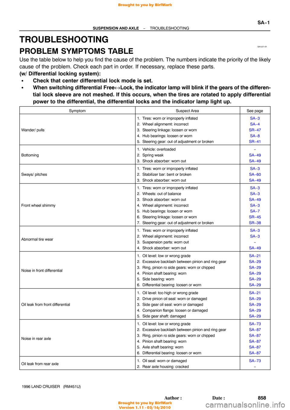
TROUBLESHOOTING
PROBLEM SYMPTOMS TABLE
Use the table below to help you find the cause of the problem. The numbers \
indicate the priority of the likely
cause of the problem. Check each part in order. If necessary, replace these parts.
(w/ Differential locking system):
�Check that center differential lock mode is set.
�When switching differential Free↔Lock, the indicator lamp will blink if the gears of the differen-
tial lock sleeve are not meshed. If this occurs, when the tires are rotated \
to apply differential
power to the differential, the differential locks and the indicator lamp\
light up.
SymptomSuspect AreaSee page
Wander/ pulls
1. Tires: worn or improperly inflated
2. Wheel alignmemt: incorrect
3. Steering linkage: loosen or worn
4. Hub bearings: loosen or worn
5. Steering gear: out of adjustment or brokenSA−3
SA−4
SR−47 SA−8
SR−41
Bottoming
1. Vehicle: overloaded
2. Spring weak
3. Shock absorber: worn out−
SA−49
SA−49
Sways/ pitches
1. Tires: worn or improperly inflated
2. Stabilizer bar: bent or broken
3. Shock absorber: worn outSA−3
SA−60
SA−49
Front wheel shimmy
1. Tires: worn or improperly inflated
2. Wheels: out of balance
3. Shock absorber: worn out
4. Wheel alignmemt: incorrect
5. Hub bearings: loosen or worn
6. Steering linkage: loosen or worn
7. Steering gear: out of adjustment or brokenSA−3
SA−3
SA−49 SA−3
SA−7
SR−45
SR−38
Abnormal tire wear
1. Tires: worn or improperly inflated
2. Wheel alignmemt: incorrect
3. Suspension parts: worn out
4. Shock absorber: worn outSA−3
SA−3 −
SA−49
Noise in front dif ferential
1. Oil level: low or wrong grade
2. Excessive backlash between pinion and ring gear
3. Ring, pinion ro side gears: worn or chipped
4. Pinion shaft bearing: worn
5. Side bearing: worn
6. Differential bearing: loosen or wornSA−21
SA−29
SA−29
SA−29
SA−29
SA−29
Oil leak from front dif ferential
1. Oil level: too high or wrong grade
2. Drive pinion oil seal: worn or damaged
3. Side gear oil seal: worn or damaged
4. Companion flange: loosen or damaged
5. Side gear shaft: damagedSA−21
SA−29
SA−29
SA−29
SA−29
Noise in rear axle
1. Oil level: low or wrong grade
2. Excessive backlash between pinion and ring gear
3. Ring, pinion ro side gears: worn or chipped
4. Pinion shaft bearing: worn
5. Axle shaft bearing: worn
6. Differential bearing: loosen or wornSA−73
SA−87
SA−87
SA−87
SA−87
SA−87
Oil leak from rear axle1. Oil seal: worn or damaged
2. Rear axle housing: crackedSA−73
−
Brought to you by BirfMark
Brought to you by BirfMark
Version 1.11 - 03/16/2010
Page 1069 of 1399
SA1UA−01
SA−6
−
SUSPENSION AND AXLE FRONT AXLE HUB
863
Author�: Date�:
1996 LAND CRUISER (RM451U)
FRONT AXLE HUB
COMPONENTS
Brought to you by BirfMark
Brought to you by BirfMark
Version 1.11 - 03/16/2010
Page 1070 of 1399

SA1UB−01
SA2635
SST
−
SUSPENSION AND AXLE FRONT AXLE HUB
SA−7
1996 LAND CRUISER (RM451U)
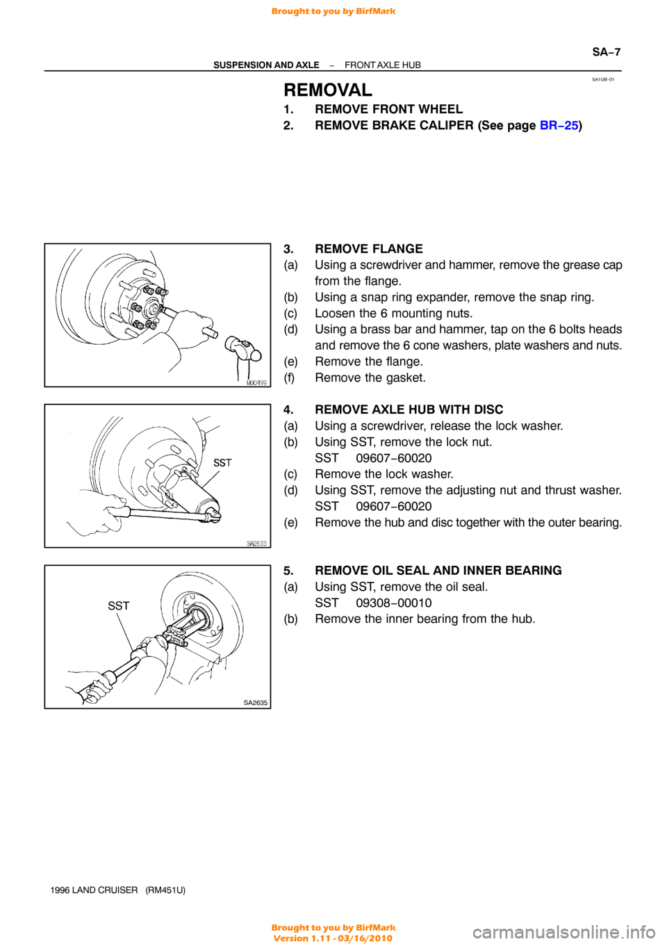
REMOVAL
1. REMOVE FRONT WHEEL
2. REMOVE BRAKE CALIPER (See page BR−25 )
3. REMOVE FLANGE
(a) Using a screwdriver and hammer, remove the grease cap
from the flange.
(b) Using a snap ring expander, remove the snap ring.
(c) Loosen the 6 mounting nuts.
(d) Using a brass bar and hammer, tap on the 6 bolts heads and remove the 6 cone washers, plate washers and nuts.
(e) Remove the flange.
(f) Remove the gasket.
4. REMOVE AXLE HUB WITH DISC
(a) Using a screwdriver, release the lock washer.
(b) Using SST, remove the lock nut. SST 09607−60020
(c) Remove the lock washer.
(d) Using SST, remove the adjusting nut and thrust washer.
SST 09607−60020
(e) Remove the hub and disc together with the outer bearing.
5. REMOVE OIL SEAL AND INNER BEARING
(a) Using SST, remove the oil seal. SST 09308−00010
(b) Remove the inner bearing from the hub.
Brought to you by BirfMark
Brought to you by BirfMark
Version 1.11 - 03/16/2010
Page 1071 of 1399

SA1UB−01
SA2635
SST
−
SUSPENSION AND AXLE FRONT AXLE HUB
SA−7
1996 LAND CRUISER (RM451U)
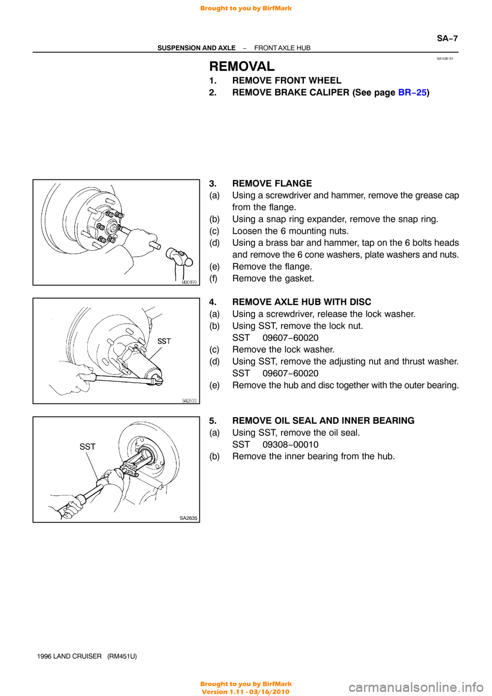
REMOVAL
1. REMOVE FRONT WHEEL
2. REMOVE BRAKE CALIPER (See page BR−25 )
3. REMOVE FLANGE
(a) Using a screwdriver and hammer, remove the grease cap
from the flange.
(b) Using a snap ring expander, remove the snap ring.
(c) Loosen the 6 mounting nuts.
(d) Using a brass bar and hammer, tap on the 6 bolts heads and remove the 6 cone washers, plate washers and nuts.
(e) Remove the flange.
(f) Remove the gasket.
4. REMOVE AXLE HUB WITH DISC
(a) Using a screwdriver, release the lock washer.
(b) Using SST, remove the lock nut. SST 09607−60020
(c) Remove the lock washer.
(d) Using SST, remove the adjusting nut and thrust washer.
SST 09607−60020
(e) Remove the hub and disc together with the outer bearing.
5. REMOVE OIL SEAL AND INNER BEARING
(a) Using SST, remove the oil seal. SST 09308−00010
(b) Remove the inner bearing from the hub.
Brought to you by BirfMark
Brought to you by BirfMark
Version 1.11 - 03/16/2010