Page 1184 of 1399
SA1VX−01
−
SUSPENSION AND AXLE REAR UPPER AND LOWER CONTROL ARM
SA−121
978
Author�: Date�:
1996 LAND CRUISER (RM451U)
REAR UPPER AND LOWER
CONTROL ARM
REMOVAL
1. REMOVE REAR WHEEL
Torque:
Steel wheel: 147 N·m (1,500 kgf·cm, 109 ft·lbf)
Aluminum wheel: 103 N·m (1,050 kgf·cm, 76 ft·lbf)
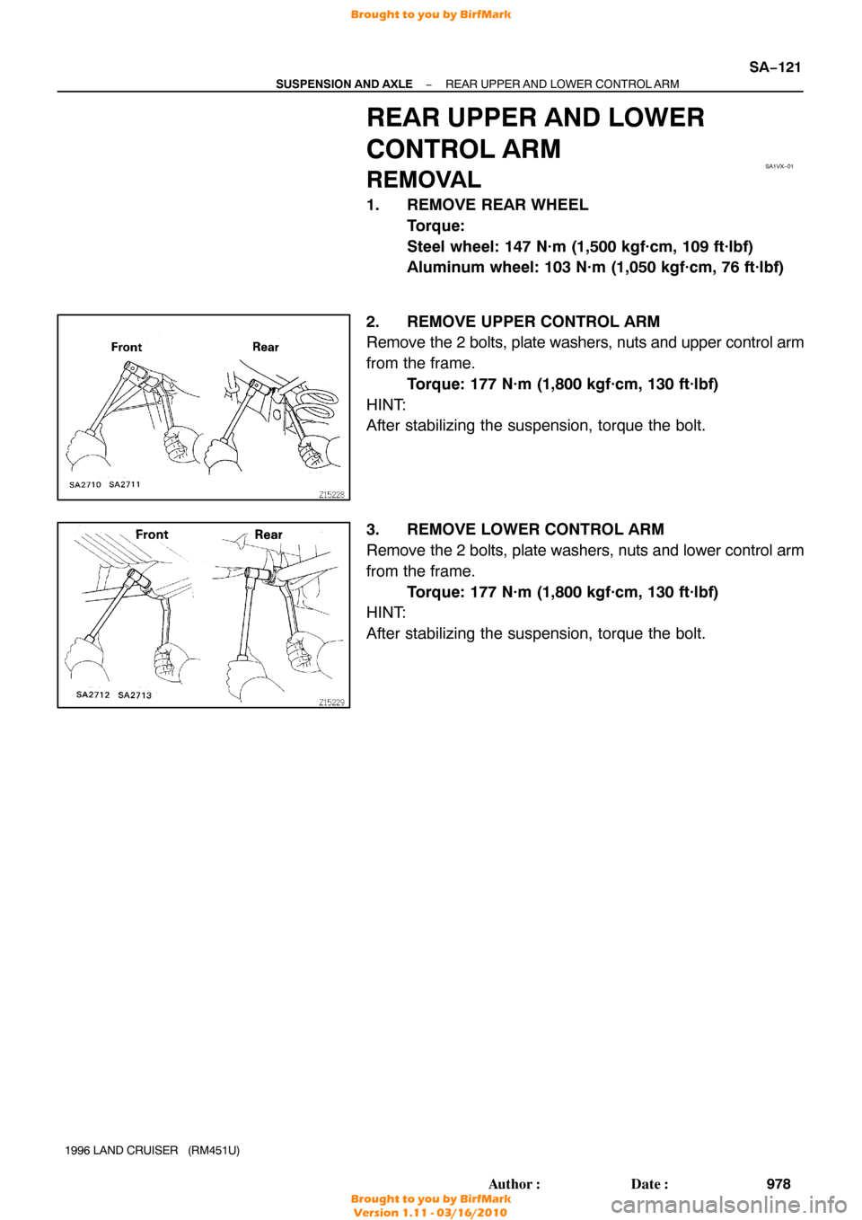
2. REMOVE UPPER CONTROL ARM
Remove the 2 bolts, plate washers, nuts and upper control arm
from the frame. Torque: 177 N·m (1,800 kgf·cm, 130 ft·lbf)
HINT:
After stabilizing the suspension, torque the bolt.
3. REMOVE LOWER CONTROL ARM
Remove the 2 bolts, plate washers, nuts and lower control arm
from the frame. Torque: 177 N·m (1,800 kgf·cm, 130 ft·lbf)
HINT:
After stabilizing the suspension, torque the bolt.
Brought to you by BirfMark
Brought to you by BirfMark
Version 1.11 - 03/16/2010
Page 1185 of 1399
SA1VY−01
R13242
SST
R13243
SSTSST
R13244
SST
W02078
SST
SA−122
−
SUSPENSION AND AXLE REAR UPPER AND LOWER CONTROL ARM
1996 LAND CRUISER (RM451U)
REPLACEMENT
1. REPLACE UPPER CONTROL ARM BUSHING
(a) Using SST and a press, remove the bushing. SST 09226 −10010, 09950 −60010 (09951 −00490),
09950 −70010 (09951 −07100)
(b) Using SST and a press, install a new bushing. SST 09226−10010, 09506 −35010
2. REPLACE LOWER CONTROL ARM BUSHING
(a) Using SST and a press, remove the bushing. SST 09506 −35010, 09950 −60010 (09951 −00540),
09950 −70010 (09951 −07100)
(b) Using SST and a press, install a new bushing, as shown.
SST 09316−20011, 09506 −35010
Brought to you by BirfMark
Brought to you by BirfMark
Version 1.11 - 03/16/2010
Page 1186 of 1399
SA1VZ−01
−
SUSPENSION AND AXLE REAR UPPER AND LOWER CONTROL ARM
SA−123
1996 LAND CRUISER (RM451U)
INSTALLATION
Installation is in the reverse order of removal (See page SA−121 ).
Brought to you by BirfMark
Brought to you by BirfMark
Version 1.11 - 03/16/2010
Page 1187 of 1399
SA1W0−01
SA−124
−
SUSPENSION AND AXLE REAR STABILIZER BAR
981
Author�: Date�:
1996 LAND CRUISER (RM451U)
REMOVAL
REMOVE STABILIZER BAR
(a) Loosen the 2 bolts and nuts.
Torque: 25 N·m (260 kgf·cm, 19 ft·lbf)
HINT:
After stabilizing the suspension, torque the nut.
(b) Remove the nuts and disconnect the stabilizer bar with the links from the bracket.
Torque: 15 N·m (153 kgf·cm, 11 ft·lbf)
HINT:
After stabilizing the suspension, torque the nut.
(c) Remove the 2 bolts, nuts and links from the stabilizer bar.
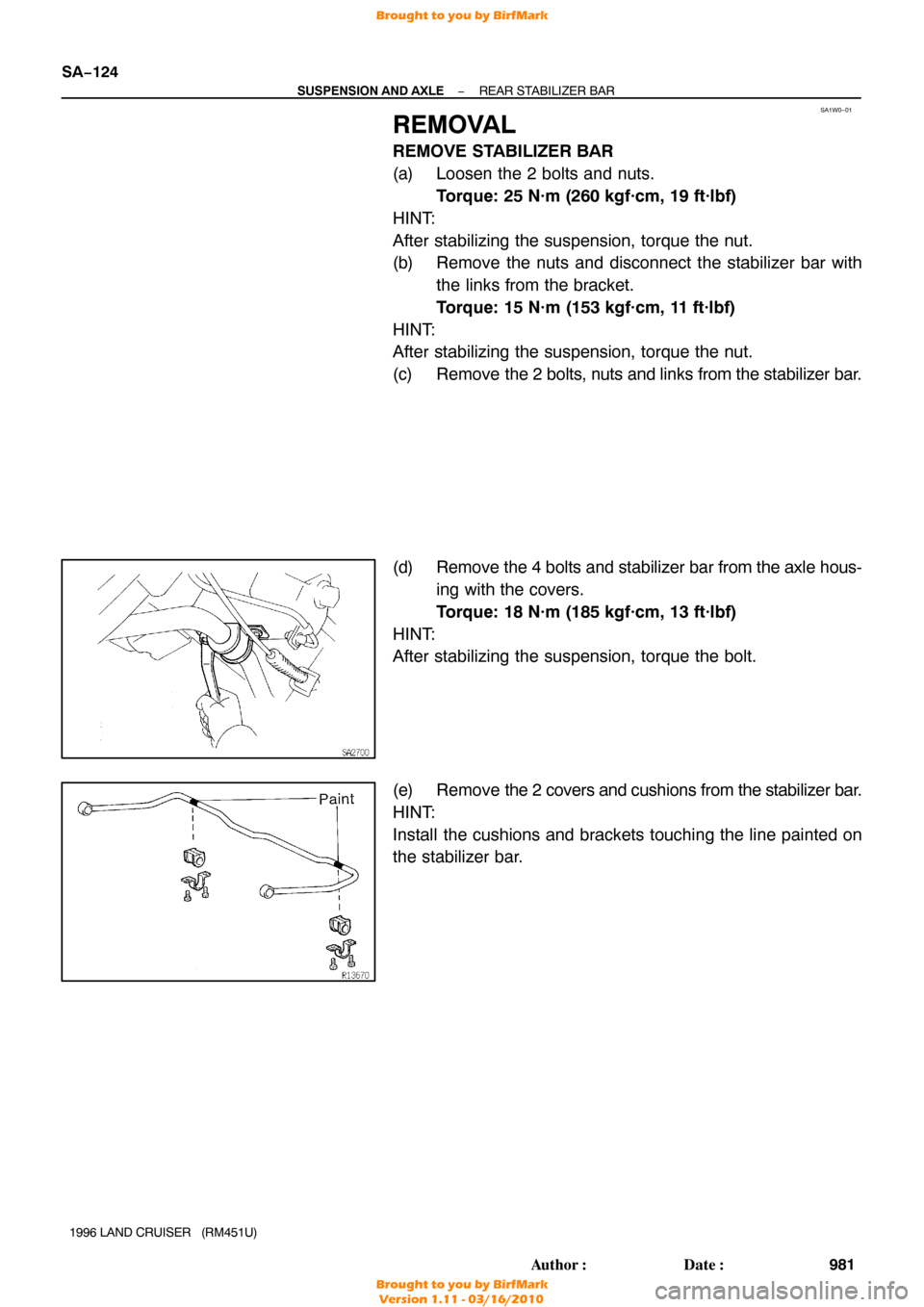
(d) Remove the 4 bolts and stabilizer bar from the axle hous- ing with the covers.
Torque: 18 N·m (185 kgf·cm, 13 ft·lbf)
HINT:
After stabilizing the suspension, torque the bolt.
(e) Remove the 2 covers and cushions from the stabilizer bar.
HINT:
Install the cushions and brackets touching the line painted on
the stabilizer bar.
Brought to you by BirfMark
Brought to you by BirfMark
Version 1.11 - 03/16/2010
Page 1188 of 1399
SA1W1−01
−
SUSPENSION AND AXLE REAR STABILIZER BAR
SA−125
1996 LAND CRUISER (RM451U)
INSTALLATION
Installation is in the reverse order of removal (See page SA−124 ).
Brought to you by BirfMark
Brought to you by BirfMark
Version 1.11 - 03/16/2010
Page 1255 of 1399

TROUBLESHOOTING
PROBLEM SYMPTOMS TABLE
Use the table below to help you find the cause of the problem. T")
SR165−01
SR−2
−
STEERING TROUBLESHOOTING
1053
Author�: Date�:
1996 LAND CRUISER (RM451U)
TROUBLESHOOTING
PROBLEM SYMPTOMS TABLE
Use the table below to help you find the cause of the problem. The numbers \
indicate the priority of the likely
cause of the problem. Check each part in the order shown. If necessary, repair or replace these parts.
SymptomSuspect AreaSee page
Hard steering
11. Tires (Improperly inflated)
12.Power steering fluid level (Low)
13.Front wheel alignment (Incorrect)
14.Steering system joints (Worn)
15.Suspension arm ball joints (W orn)
16.Steering column (Binding)
17.Power steering vane pump
18.Power steering gearSA−3
SR−4 SA−4 −
−
−
SR−21
SR−33
Poor return
1. Tires (Improperly inflated)
2. Front wheel alignment (Incorrect)
3. Steering column (Binding)
4. Power steering gearSA−3
SA−4 −
SR−33
Excessive play
1. Steering system joints (Worn)
2. Suspension arm ball joints (W orn)
3. Intermediate shaft, Universal joint, Sliding yoke (Worn)
4. Front wheel bearing (W orn)
5. Power steering gear−
−
−
SR−7
SR−33
Abnormal noise
1. Power steering fluid level (Low)
2. Steering system joints (Worn)
3. Power steering vane pump
4. Power steering gearSR−4 −
SR−21
SR−33
Brought to you by BirfMark
Brought to you by BirfMark
Version 1.11 - 03/16/2010
Page 1331 of 1399

SUSPENSION AND AXLE
SERVICE DATA
Cold tire inflation
pressureTire size
P275/70R 16")
SS1EC−02
SS−30
−
SERVICE SPECIFICATIONS SUSPENSION AND AXLE
153
Author�: Date�:
1996 LAND CRUISER (RM451U)
SUSPENSION AND AXLE
SERVICE DATA
Cold tire inflation
pressureTire size
P275/70R 16
220 kPa (2.2 kgf/cm2, 32 psi)
Follow spring and
bumper stopper
clearanceFollow spring clearance (Front)
Bumper stopper clearance (Rear)36 mm (1.42 in.)
104 mm (4.09 in.)
Front wheel align-
mentCamber Left−right error1°00’ ± 45’
45’ or less
Caster Left−right error3°00’ ± 60’
45’ or less
Steering axis inclination13 °00’ ± 45’
To e −in (Total) Inspection STD
Adjustment STD0.2 ° ± 0.2° (2 ± 2 mm, 0.08 ± 0.08 in.)
0.2 ° ± 0.1° (2 ± 1 mm, 0.08 ± 0.04 in.)
Wheel angle (Max.) Inside wheel
Outside wheel32 °00’ − 35°00’
31 °00’
Tire and wheelTire runout
Wheel balance (Unbalance after adjustment)
Wheel bearing preload (at starting) Front
(Rotating load at hub bolt) Rear3.0 mm (0.118 in.) or less
13.0 g (0.029 lb) or less
28 − 56 N (2.9 − 5.7 kgf, 6.4 − 12.6 lbf)
26 − 57 N (2.6 − 5.8 kgf, 5.7 − 12.8 lbf)
Front axleSteering knuckle bearing preload
(Rotating load at knuckle end, before installing dust seal)
25 − 44 N (2.5 − 4.5 kgf, 5.5 − 9.9 lbf)
Front dif ferentialDrive pinion preload (at starting) New bearing
Reused bearing0.9 − 1.6 N·m (10 − 16 kgf·cm, 8.7 − 13.9 in.·lbf)
0.5 − 0.8 N·m (5 − 8 kgf·cm, 4.3 − 6.9 in.·lbf)
Total preload (at starting)Drive pinion preload plus
0.4 − 0.6 N·m (4 − 6 kgf·cm, 3.5 − 5.2 in.·lbf)
Drive pinion to ring gear backlash0.13 − 0.18 mm (0.0051 − 0.0071 in.)
Pinion gear to side gear backlash0.05 − 0.20 mm (0.0020 − 0.0079 in.)
Ring gear runout Max.0.10 mm (0.0039 in.)
Companion flange runoutMax. Radial
Lateral0.10 mm (0.0039 in.)
0.10 mm (0.0039 in.)
Oil seal drive in depth1.0 mm (0.039 in.)
Side gear thrust washer thickness w/o Differntial lock
w/ Differntial lock1.6 mm (0.063 in.)
1.7 mm (0.067 in.)
1.8 mm (0.071 in.)
0.9 mm (0.035 in.)
1.0 mm (0.039 in.)
1.1 mm (0.043 in.)
1.2 mm (0.047 in.)
1.3 mm (0.051 in.)
Brought to you by BirfMark
Brought to you by BirfMark
Version 1.11 - 03/16/2010
Page 1332 of 1399

Front dif
ferential
(cont’d)
Drive pinion adjusting plate washer thickness1.70 mm (0.0669 in.)")
−
SERVICE SPECIFICATIONS SUSPENSION AND AXLE
SS−31
154
Author�: Date�:
1996 LAND CRUISER (RM451U)
Front dif
ferential
(cont’d)
Drive pinion adjusting plate washer thickness1.70 mm (0.0669 in.)
1.73 mm (0.0681 in.)
1.76 mm (0.0693 in.)
1.79 mm (0.0705 in.)
1.82 mm (0.0717 in.)
1.85 mm (0.0728 in.)
1.88 mm (0.0740 in.)
1.91 mm (0.0752 in.)
1.94 mm (0.0764 in.)
1.97 mm (0.0776 in.)
2.00 mm (0.0787 in.)
2.03 mm (0.0799 in.)
2.06 mm (0.0811 in.)
2.09 mm (0.0823 in.)
2.12 mm (0.0835 in.)
2.15 mm (0.0846 in.)
2.18 mm (0.0858 in.)
2.21 mm (0.0870 in.)
2.24 mm (0.0882 in.)
2.27 mm (0.0894 in.)
2.30 mm (0.0906 in.)
2.33 mm (0.0917 in.)
Rear dif ferentialDrive pinion preload (at starting) New bearing
Reused bearing1.3 − 2.0 N·m (13 − 20 kgf·cm, 11.3 − 17.4 in.·lbf)
0.7 − 1.0 N·m (7 − 10 kgf·cm, 6.1 − 8.7 in.·lbf)
Total preload (at starting)
w/o Differntial lockw/ Differntial lockDrive pinion preload plus
0.4 − 0.6 N·m (4 − 6 kgf·cm, 3.5 − 5.2 in.·lbf)
0.3 − 0.7 N·m (3 − 7 kgf·cm, 2.6 − 6.1 in.·lbf)
Drive pinion to ring gear backlash0.15 − 0.20 mm (0.0059 − 0.0079 in.)
Pinion gear to side gear backlash0.02 − 0.20 mm (0.0008 − 0.0079 in.)
Ring gear runout Max.0.10 mm (0.0039 in.)
Companion flange runoutMax. Radial
Lateral0.10 mm (0.0039 in.)
0.10 mm (0.0039 in.)
Oil seal drive in depth1.0 mm (0.039 in.)
Side gear thrust washer thickness1.60 mm (0.0630 in.)
1.75 mm (0.0689 in.)
1.90 mm (0.0748 in.)
2.05 mm (0.0807 in.)
Drive pinion adjusting plate washer thickness1.05 mm (0.0413 in.)
1.10 mm (0.0433 in.)
1.15 mm (0.0453 in.)
1.20 mm (0.0472 in.)
1.25 mm (0.0492 in.)
1.30 mm (0.0512 in.)
1.35 mm (0.0531 in.)
1.40 mm (0.0551 in.)
1.45 mm (0.0571 in.)
1.50 mm (0.0591 in.)
1.55 mm (0.0610 in.)
Brought to you by BirfMark
Brought to you by BirfMark
Version 1.11 - 03/16/2010

REPLACEMENT
1. REPLACE UPPER CONTROL ARM BUSHIN")

INSTALLATION
Installation is in the reverse order of removal (See page SA−121 ).
Brought to")

INSTALLATION
Installation is in the reverse order of removal (See page SA−124 ).
Brought to you by Birf")