Page 1157 of 1399
Z06953SST
SA2444
SA−94
−
SUSPENSION AND AXLE REAR DIFFERENTIAL CARRIER
1996 LAND CRUISER (RM451U)
14. w/o DIFFERENTIAL LOCK:
INSTALL ADJUSTING NUTS
Install the 2 adjusting nuts on the carrier, making sure the nuts
are threaded properly.
15. w/o DIFFERENTIAL LOCK: INSTALL BEARING CAPS
Align the matchmarks on the cap and carrier. Screw in the 2
bearing cap bolts 2 or 3 turns and press down the bearing cap
by hand.
HINT:
If the bearing cap does not fit tightly on the carrier , the adjusting
nuts are not threaded properly.
Reinstall the adjusting nuts if necessary.
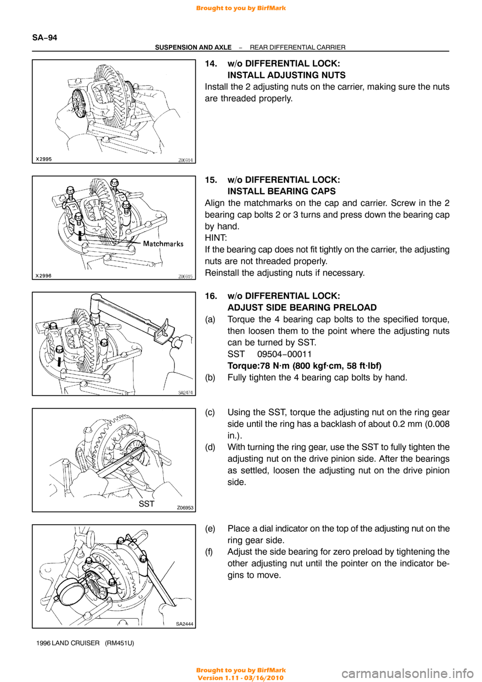
16. w/o DIFFERENTIAL LOCK: ADJUST SIDE BEARING PRELOAD
(a) Torque the 4 bearing cap bolts to the specified torque, then loosen them to the point where the adjusting nuts
can be turned by SST.
SST 09504−00011
Torque:78 N·m (800 kgf·cm, 58 ft·lbf)
(b) Fully tighten the 4 bearing cap bolts by hand.
(c) Using the SST, torque the adjusting nut on the ring gear side until the ring has a backlash of about 0.2 mm (0.008
in.).
(d) With turning the ring gear, use the SST to fully tighten the
adjusting nut on the drive pinion side. After the bearings
as settled, loosen the adjusting nut on the drive pinion
side.
(e) Place a dial indicator on the top of the adjusting nut on the ring gear side.
(f) Adjust the side bearing for zero preload by tightening the
other adjusting nut until the pointer on the indicator be-
gins to move.
Brought to you by BirfMark
Brought to you by BirfMark
Version 1.11 - 03/16/2010
Page 1158 of 1399
Z06918
−
SUSPENSION AND AXLE REAR DIFFERENTIAL CARRIER
SA−95
1996 LAND CRUISER (RM451U)
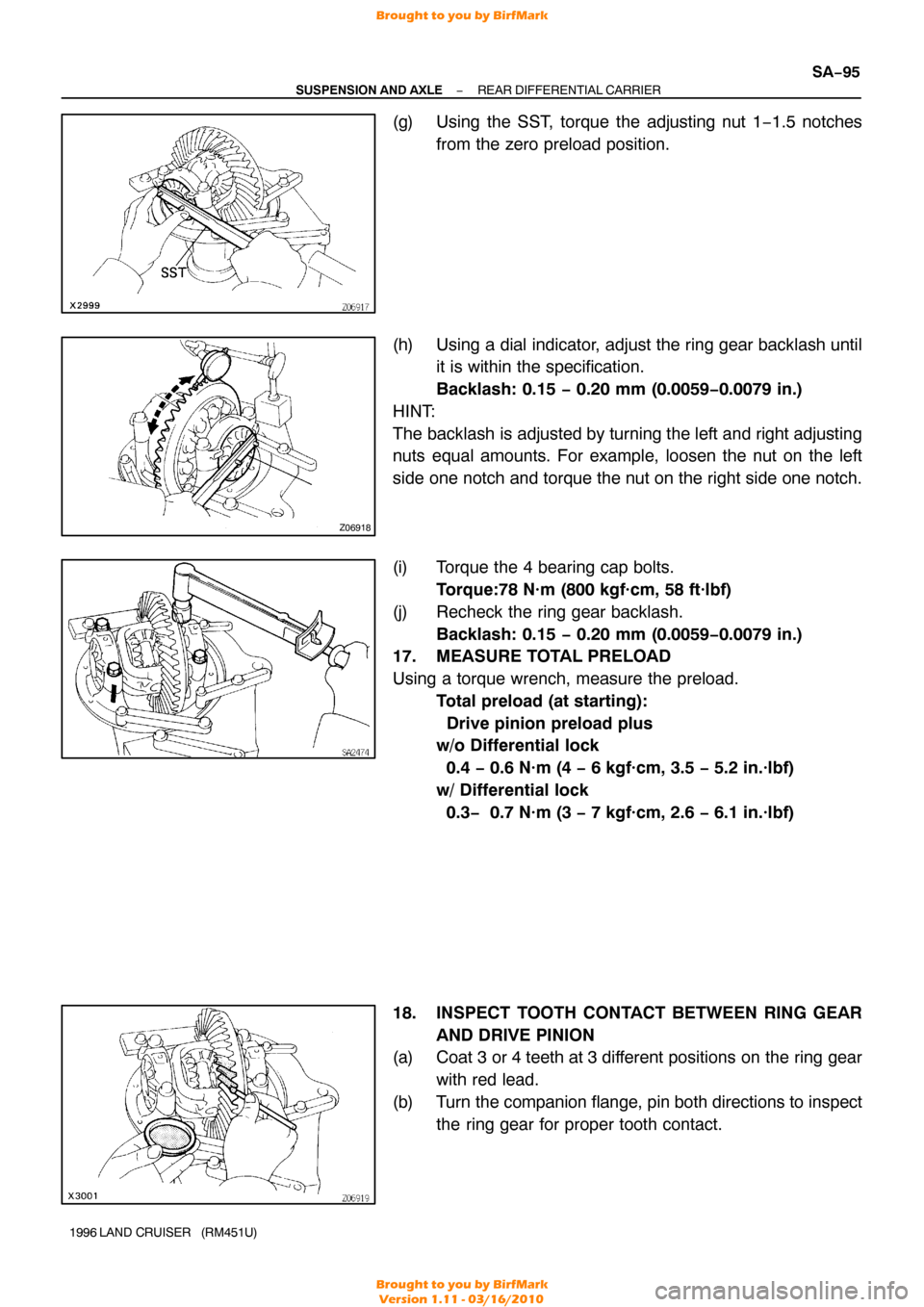
(g) Using the SST, torque the adjusting nut 1−1.5 notches
from the zero preload position.
(h) Using a dial indicator, adjust the ring gear backlash until it is within the specification.
Backlash: 0.15 − 0.20 mm (0.0059−0.0079 in.)
HINT:
The backlash is adjusted by turning the left and right adjusting
nuts equal amounts. For example, loosen the nut on the left
side one notch and torque the nut on the right side one notch.
(i) Torque the 4 bearing cap bolts. Torque:78 N·m (800 kgf·cm, 58 ft·lbf)
(j) Recheck the ring gear backlash. Backlash: 0.15 − 0.20 mm (0.0059−0.0079 in.)
17. MEASURE TOTAL PRELOAD
Using a torque wrench, measure the preload.
Total preload (at starting):
Drive pinion preload plus
w/o Differential lock
0.4 − 0.6 N·m (4 − 6 kgf·cm, 3.5 − 5.2 in.·lbf)
w/ Differential lock
0.3− 0.7 N·m (3 − 7 kgf·cm, 2.6 − 6.1 in.·lbf)
18. INSPECT TOOTH CONTACT BETWEEN RING GEAR AND DRIVE PINION
(a) Coat 3 or 4 teeth at 3 different positions on the ring gear
with red lead.
(b) Turn the companion flange, pin both directions to inspect the ring gear for proper tooth contact.
Brought to you by BirfMark
Brought to you by BirfMark
Version 1.11 - 03/16/2010
Page 1159 of 1399
FA2013
Proper ContactHeel Contact
Face Contact
Select an adjusting washer that will bring the drive
pinion closer to the ring gear.
Select an adjusting washer that will shift the drive
pinion away from the ring gear.
Toe Contact
Flank Contact
FA2041
Washer
SA2394
SA−96
−
SUSPENSION AND AXLE REAR DIFFERENTIAL CARRIER
1996 LAND CRUISER (RM451U)
If the teeth are not contacting properly, use the following chart
to select a proper washer for correction.
Thickness mm (in.)Thickness mm (in.)
1.05 (0.0413)1.35 (0.0531)
1.10 (0.0433)1.40 (0.0551)
1.15 (0.0453)1.45 (0.0571)
1.20 (0.0472)1.50 (0.0591)
1.25 (0.0492)1.55 (0.0610)
1.30 (0.0512)−
19. REMOVE COMPANION FLANGE (See page SA−29)
20. REMOVE OIL SLINGER AND FRONT BEARING (See
page SA−29 )
21. INSTALL BEARING SPACER AND FRONT BEARING
(a) Install a new bearing spacer on the shaft.
(b) Install the front bearing and oil slinger.
Brought to you by BirfMark
Brought to you by BirfMark
Version 1.11 - 03/16/2010
Page 1160 of 1399
SA2454
SST
R13414
SST
SA2351
SST
SA2446
−
SUSPENSION AND AXLE REAR DIFFERENTIAL CARRIER
SA−97
1996 LAND CRUISER (RM451U)
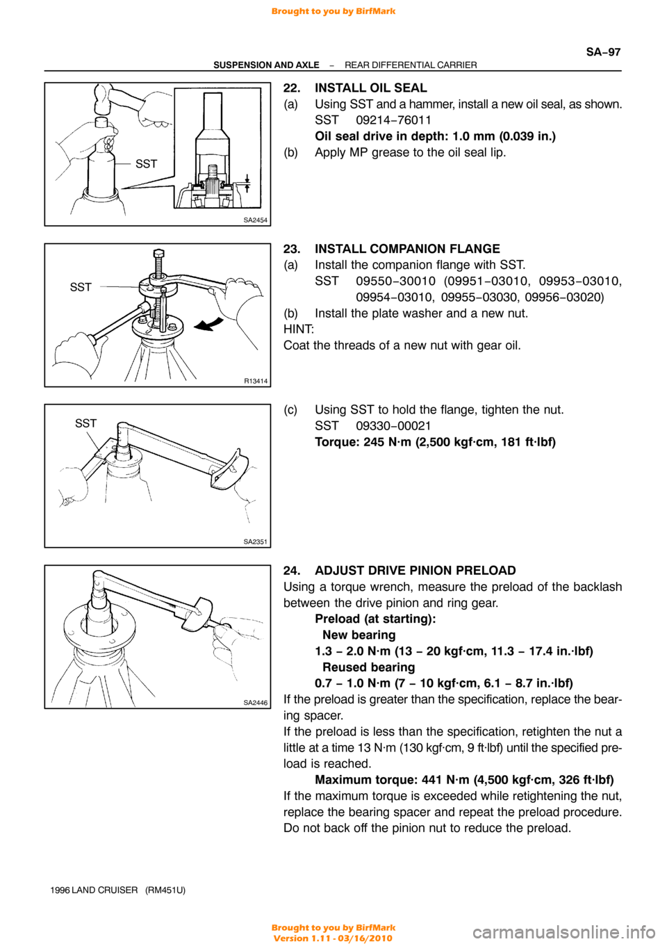
22. INSTALL OIL SEAL
(a) Using SST and a hammer, install a new oil seal, as shown.
SST 09214−76011
Oil seal drive in depth: 1.0 mm (0.039 in.)
(b) Apply MP grease to the oil seal lip.
23. INSTALL COMPANION FLANGE
(a) Install the companion flange with SST. SST 09550 −30010 (09951 −03010, 09953 −03010,
09954 −03010, 09955 −03030, 09956−03020)
(b) Install the plate washer and a new nut.
HINT:
Coat the threads of a new nut with gear oil.
(c) Using SST to hold the flange, tighten the nut. SST 09330−00021
Torque: 245 N·m (2,500 kgf·cm, 181 ft·lbf)
24. ADJUST DRIVE PINION PRELOAD
Using a torque wrench, measure the preload of the backlash
between the drive pinion and ring gear. Preload (at starting):
New bearing
1.3 − 2.0 N·m (13 − 20 kgf·cm, 11.3 − 17.4 in.·lbf)
Reused bearing
0.7 − 1.0 N·m (7 − 10 kgf·cm, 6.1 − 8.7 in.·lbf)
If the preload is greater than the specification, replace the bear-
ing spacer.
If the preload is less than the specification, retighten the nut a
little at a time 13 N·m (130 kgf·cm, 9 ft·lbf) until the specified pre-
load is reached. Maximum torque: 441 N·m (4,500 kgf·cm, 326 ft·lbf)
If the maximum torque is exceeded while retightening the nut,
replace the bearing spacer and repeat the preload procedure.
Do not back off the pinion nut to reduce the preload.
Brought to you by BirfMark
Brought to you by BirfMark
Version 1.11 - 03/16/2010
Page 1161 of 1399
Z15220
FIPG Width Approx.
1 − 2 mm (0.04 − 0.08 in.)
SA2129
Z10150
Adhesive
SA−98
−
SUSPENSION AND AXLE REAR DIFFERENTIAL CARRIER
1996 LAND CRUISER (RM451U)
25. RECHECK RING GEAR BACKLASH
Using a dial indicator, measure the ring gear backlash.
Ring gear backlash:
0.15 − 0.20 mm (0.0059 − 0.0079 in.)
26. RECHECK TOOTH CONTACT BETWEEN RING GEAR AND DRIVE PINION
27. CHECK RUNOUT OF COMPANION FLANGE (See
page SA−80 )
28. w/o DIFFERENTIAL LOCK: INSTALL ADJUSTING NUT LOCKS
(a) Install 2 new nut locks on the bearing caps.
(b) Tightening 2 bolts, bend the nut locks. Torque: 13 N·m (130 kgf·cm, 9 ft·lbf)
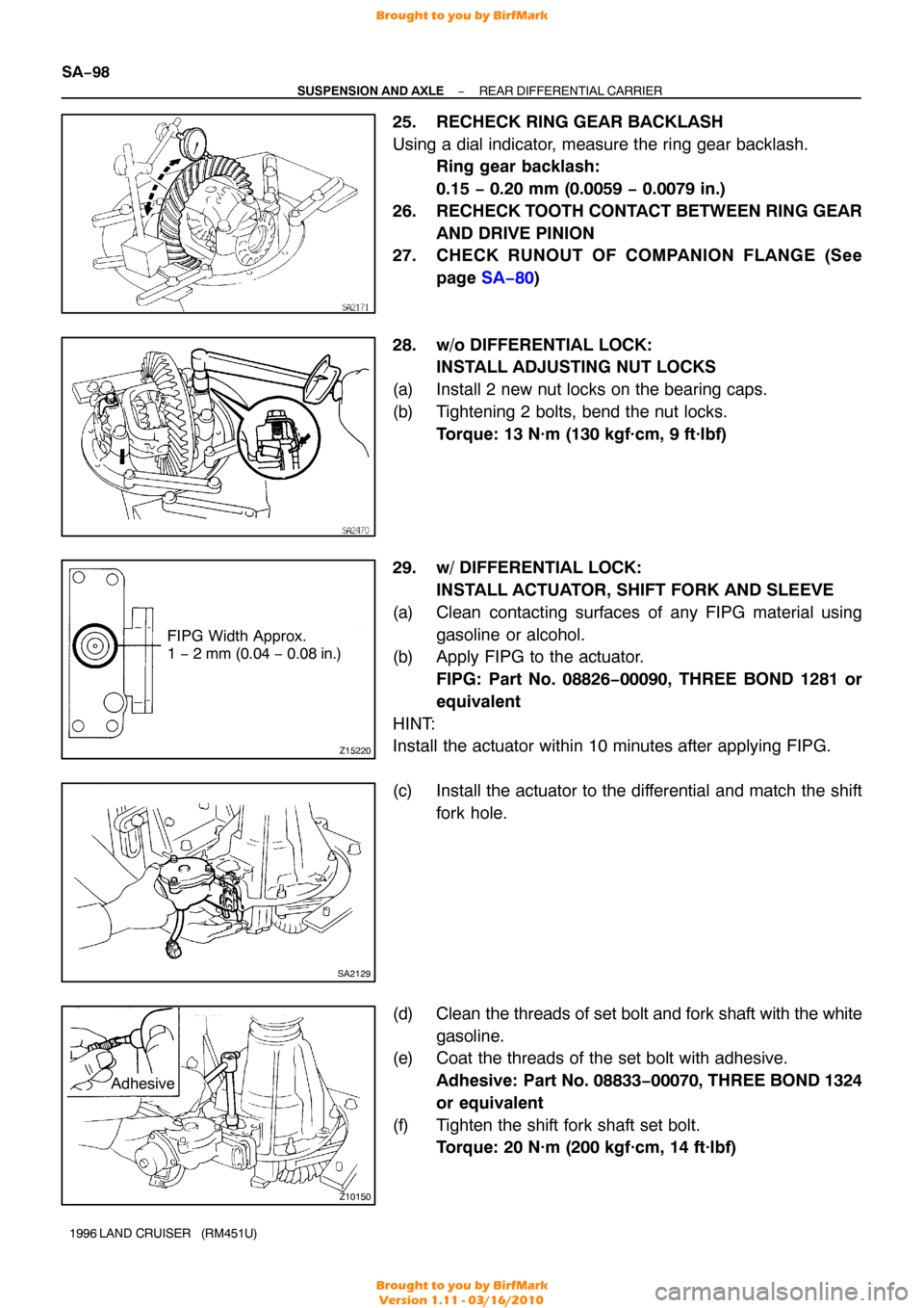
29. w/ DIFFERENTIAL LOCK: INSTALL ACTUATOR, SHIFT FORK AND SLEEVE
(a) Clean contacting surfaces of any FIPG material using gasoline or alcohol.
(b) Apply FIPG to the actuator.
FIPG: Part No. 08826−00090, THREE BOND 1281 or
equivalent
HINT:
Install the actuator within 10 minutes after applying FIPG.
(c) Install the actuator to the differential and match the shift fork hole.
(d) Clean the threads of set bolt and fork shaft with the white
gasoline.
(e) Coat the threads of the set bolt with adhesive.
Adhesive: Part No. 08833 −00070, THREE BOND 1324
or equivalent
(f) Tighten the shift fork shaft set bolt. Torque: 20 N·m (200 kgf·cm, 14 ft·lbf)
Brought to you by BirfMark
Brought to you by BirfMark
Version 1.11 - 03/16/2010
Page 1162 of 1399
SA2133
SA2131
Z15219
FIPG Width Approx.
1 − 2 mm (0.04 − 0.08 in.)
−
SUSPENSION AND AXLE REAR DIFFERENTIAL CARRIER
SA−99
1996 LAND CRUISER (RM451U)
(g) Engage the sleeve with the dog clutch of the differential
case.
(h) Tighten the 4 bolts. Torque: 24 N·m (240 kgf·cm, 17 ft·lbf)
30. w/ DIFFERENTIAL LOCK: INSTALL COVER
(a) Clean contacting surfaces of any FIPG material using gasoline or alcohol.
(b) Apply FIPG to the cover.
FIPG: Part No. 08826−00090, THREE BOND 1281 or
equivalent
HINT:
Install the cover within 10 minutes after applying FIPG.
(c) Tighten the 3 bolts. Torque: 18 N·m (185 kgf·cm, 13 ft·lbf)
31. w/ DIFFERENTIAL LOCK: INSTALL INDICATOR SWITCH
Install the indicator switch with a new gasket.
Torque: 40 N·m (410 kgf·cm, 30 ft·lbf)
Brought to you by BirfMark
Brought to you by BirfMark
Version 1.11 - 03/16/2010
Page 1163 of 1399
SA1VK−01
SA−100
−
SUSPENSION AND AXLE REAR DIFFERENTIAL CARRIER
1996 LAND CRUISER (RM451U)
INSTALLATION
Installation is in the reverse order of removal (See page SA−79 ).
HINT:
After installation, fill the differential with gear oil (See page SA−27).
Brought to you by BirfMark
Brought to you by BirfMark
Version 1.11 - 03/16/2010
Page 1164 of 1399
SA1VL−03
−
SUSPENSION AND AXLE DIFFERENTIAL LOCKING SYSTEM
SA−101
958
Author�: Date�:
1996 LAND CRUISER (RM451U)
DIFFERENTIAL LOCKING SYSTEM
ON−VEHICLE INSPECTION
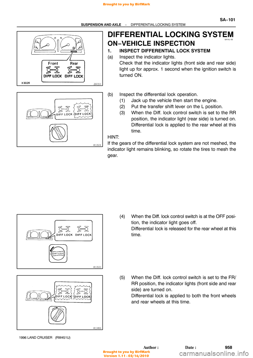
1. INSPECT DIFFERENTIAL LOCK SYSTEM
(a) Inspect the indicator lights.
Check that the indicator lights (front side and rear side)
light up for approx. 1 second when the ignition switch is
turned ON.
(b) Inspect the differential lock operation. (1) Jack up the vehicle then start the engine.
(2) Put the transfer shift lever on the L position.
(3) When the Diff. lock control switch is set to the RR
position, the indicator light (rear side) is turned on.
Differential lock is applied to the rear wheel at this
time.
HINT:
If the gears of the differential lock system are not meshed, the
indicator light remains blinking, so rotate the tires to mesh the
gear.
(4) When the Diff. lock control switch is at the OFF posi-
tion, the indicator light goes off.
Differential lock is released for the rear wheel at this
time.
(5) When the Diff. lock control switch is set to the FR/ RR position, the indicator lights (front side and rear
side) are turned on.
Differential lock is applied to both the front wheels
and rear wheels at this time.
Brought to you by BirfMark
Brought to you by BirfMark
Version 1.11 - 03/16/2010