Page 824 of 1399
−
ENGINE MECHANICAL CYLINDER HEAD
EM−39
1996 LAND CRUISER (RM451U)
(d) Using compressed air and a magnetic finger, remove the
spring seat by blowing air.
HINT:
Arrange the valves, valve springs, spring seats and spring re-
tainers in correct order.
13. REMOVE ECT SENDER GAUGE
14. REMOVE ECT CUT SWITCH
15. REMOVE ECT SENSOR
16. REMOVE TVV
Brought to you by BirfMark
Brought to you by BirfMark
Version 1.11 - 03/16/2010
Page 828 of 1399

P03849
Overall Length
EM0255
P04415
−
ENGINE MECHANICAL CYLINDER HEAD
EM−43
1996 LAND CRUISER (RM451U)
(d) Check the valve overall length.
Standard overall length:
Intake98.4 mm (3.874 in.)
Exhaust97.4 mm (3.854 in.)
Minimum overall length:
Intake97.9 mm (3.854 in.)
Exhaust97.4 mm (3.835 in.)
If the overall length is less than minimum, replace the valve.
(e) Check the surface of the valve stem tip for wear.
If the valve stem tip is worn, resurface the tip with a grinder or
replace the valve.
NOTICE:
Do not grind off more than minimum.
7. INSPECT AND CLEAN VALVE SEATS
(a) Using a 45° carbide cutter, resurface the valve seats.
Remove only enough metal to clean the seats.
(b) Check the valve seating position. Apply a light coat of prussian blue (or white lead) to the
valve face. Lightly press the valve against the seat. Do not
rotate valve.
(c) Check the valve face and seat for the following:
�If blue appears 360 ° around the face, the valve is
concentric. If not, replace the valve.
�If blue appears 360 ° around the valve seat, the
guide and face are concentric. If not, resurface the
seat.
�Check that the seat contact is in the middle of the
valve face with these width:
Intake1.2 − 1.6 mm (0.047 − 0.063 in.)
Exhaust1.0 − 1.4 mm (0.039 − 0.055 in.)
Brought to you by BirfMark
Brought to you by BirfMark
Version 1.11 - 03/16/2010
Page 829 of 1399
EM0988
Deviation
EM0801
EM−44
−
ENGINE MECHANICAL CYLINDER HEAD
1996 LAND CRUISER (RM451U)
If not, correct the valve seats as follows: (1) Intake:If the seating is too high on the valve face, use 30 °
and 45 ° cutters to correct the seat.
(2) If the seating is too low on the valve face, use 75° and 45 ° cutters to correct the seat.
(d) Hand−lap the valve and valve seat with an abrasive com- pound.
(e) After hand−lapping, clean the valve and valve seat.
8. INSPECT VALVE SPRINGS
(a) Using a steel square, measure the deviation of the valve spring.
Maximum deviation: 2.0 mm (0.079 in.)
If the deviation is greater than maximum, replace the valve
spring.
(b) Using vernier calipers, measure the free length of the valve spring.
Free length: 43.94 − 45.06 mm (1.7299 − 1.7740 in.)
If the free length is not as specified, replace the valve spring.
Brought to you by BirfMark
Brought to you by BirfMark
Version 1.11 - 03/16/2010
Page 934 of 1399

MA02Q−04
MA−2
−
MAINTENANCE INSIDE VEHICLE
42
Author�: Date�:
1996 LAND CRUISER (RM451U)
INSIDE VEHICLE
GENERAL MAINTENANCE
The owners are responsible for these maintenance and inspection items.
They can be done by the owner or they can have them done at a service sh\
op.
These items include those which should be checked on a daily basis, thos\
e which, in most cases, do not
require (special) tools and those which are considered to be reasonabl\
e for the owner to do.
Items and procedures for general maintenance are as follows.
1. GENERAL NOTES
�Maintenance items may vary from country to country. Check the owner’s manual supplement in which
the maintenance schedule is shown.
�Every service item in the periodic maintenance schedule must be performe\
d.
�Periodic maintenance service must be performed according to whichever interval in\
the periodic main-
tenance schedule occurs first, the odometer reading (miles) or the time inter\
val (months).
�Maintenance service after the last period should be performed at the same interval \
as before unless
otherwise noted.
�Failure to do even one item can cause the engine to run poorly and incre\
ase exhaust emissions.
2. LIGHTS
(a) Check that the headlights, stop lights, taillights, turn signal lights, \
and other lights are all working.
(b) Check the headlights aim.
3. WARNING LIGHTS AND BUZZERS
Check that all warning lights and buzzers function properly.
4. HORN
Check that it is working.
5. WINDSHIELD
Check for scratches, pits or abrasions.
6. WINDSHIELD WIPER AND WASHER
(a) Check operation of the wipers and washer.
(b) Check that the wipers do not streak.
7. WINDSHIELD DEFROSTER
Check that air comes out from the defroster outlet when operating the heater \
or air conditioner at defroster
mode.
8. REAR VIEW MIRROR
Check that it is mounted securely.
9. SUN VISORS
Check that they move freely and mounted securely.
10. STEELING WHEEL
Check that it has the specified freeplay. Be alert for changes in steering condition, such as hard steering,
excessive freeplay or strange noises.
11. SEATS
(a) Check that all front seat controls such as seat adjusters, seatback recl\
iner, etc. operate smoothly.
(b) Check that all latches lock securely in any position.
(c) Check that the head restraints move up and down smoothly and that the lo\
cks hold securely in any latch position.
(d) For folding −down rear seat backs, check that the latches look securely.
12. SEAT BELTS
(a) Check that the seat belt system such as buckles, retractors and anchors operat\
e properly and smooth-
ly.
(b) Check that the belt webbing is not cut, frayed, worn or damaged.
Brought to you by BirfMark
Brought to you by BirfMark
Version 1.11 - 03/16/2010
Page 941 of 1399

MA04W−01
−
MAINTENANCE BODY
MA−9
49
Author�: Date�:
1996 LAND CRUISER (RM451U)
BODY
INSPECTION
1. TIGHTEN BOLTS AND NUTS ON CHASSIS AND BODY
(a) Tighten the front seat−to−body mounting bolts. Torque: 39 N·m (400 kgf·cm, 29 ft·lbf)
(b) Under Severe Conditions: In addition to the above maintenance items, check for
loose or missing nuts and bolts on the steering system,
drive train, suspension system, fuel tank mounts, engine
mounts, etc.
2. FINAL INSPECTION
(a) Check the operation of the body parts:
�Hood:
Auxiliary catch operates properly
Hood locks securely when closed
�Front and rear doors:
Door locks operate properly
Doors close properly
�Back door:
Door lock operates properly
�Seats:
Seat adjusts easily and locks securely in any posi-
tion
Front seat back locks securely in any position
Folding −down rear seat backs look securely
(b) Road test
�Check the engine and chassis for abnormal noises.
�Check that the vehicle does not wander or pull to
one side.
�Check that the brakes work properly and do not
drag.
(c) Be sure to deliver a clean car. Especially check the steering wheel, shift lever knob, all
switch knobs, door handles and seats.
Brought to you by BirfMark
Brought to you by BirfMark
Version 1.11 - 03/16/2010
Page 1196 of 1399

SF1EH−02
−
SFI FUEL PUMP
SF−11
1996 LAND CRUISER (RM451U)
REMOVAL
CAUTION:
Do not smoke or work near an open flame when working on
the fuel pump.
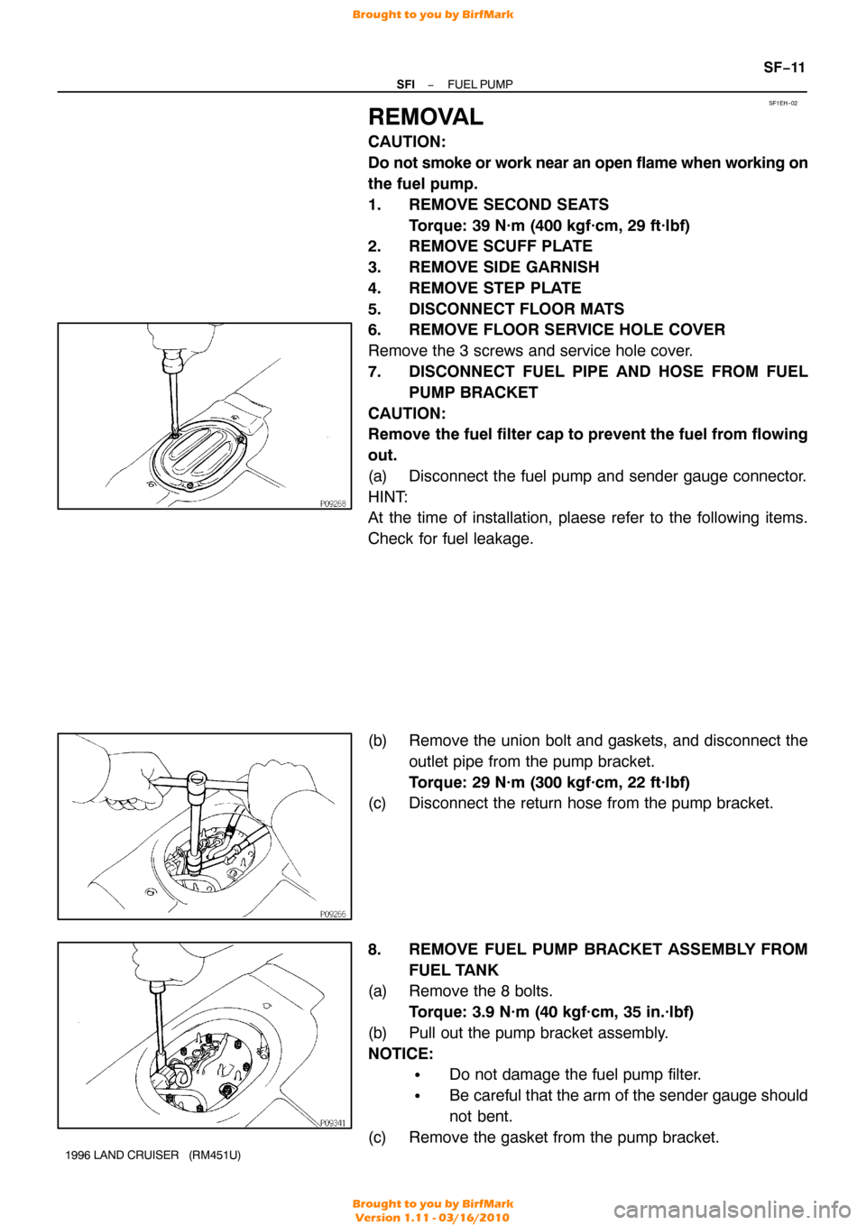
1. REMOVE SECOND SEATS
Torque: 39 N·m (400 kgf·cm, 29 ft·lbf)
2. REMOVE SCUFF PLATE
3. REMOVE SIDE GARNISH
4. REMOVE STEP PLATE
5. DISCONNECT FLOOR MATS
6. REMOVE FLOOR SERVICE HOLE COVER
Remove the 3 screws and service hole cover.
7. DISCONNECT FUEL PIPE AND HOSE FROM FUEL
PUMP BRACKET
CAUTION:
Remove the fuel filter cap to prevent the fuel from flowing
out.
(a) Disconnect the fuel pump and sender gauge connector.
HINT:
At the time of installation, plaese refer to the following items.
Check for fuel leakage.
(b) Remove the union bolt and gaskets, and disconnect the outlet pipe from the pump bracket.
Torque: 29 N·m (300 kgf·cm, 22 ft·lbf)
(c) Disconnect the return hose from the pump bracket.
8. REMOVE FUEL PUMP BRACKET ASSEMBLY FROM
FUEL TANK
(a) Remove the 8 bolts.
Torque: 3.9 N·m (40 kgf·cm, 35 in.·lbf)
(b) Pull out the pump bracket assembly.
NOTICE:
�Do not damage the fuel pump filter.
�Be careful that the arm of the sender gauge should
not bent.
(c) Remove the gasket from the pump bracket.
Brought to you by BirfMark
Brought to you by BirfMark
Version 1.11 - 03/16/2010
Page 1199 of 1399

SF1EG−02
SF−14
−
SFI FUEL PUMP
1996 LAND CRUISER (RM451U)
INSPECTION
1. REMOVE SECOND SEATS
2. REMOVE SCUFF PLATE
3. REMOVE SIDE GARNISH
4. REMOVE STEP PLATE
5. DISCONNECT FLOOR MATS
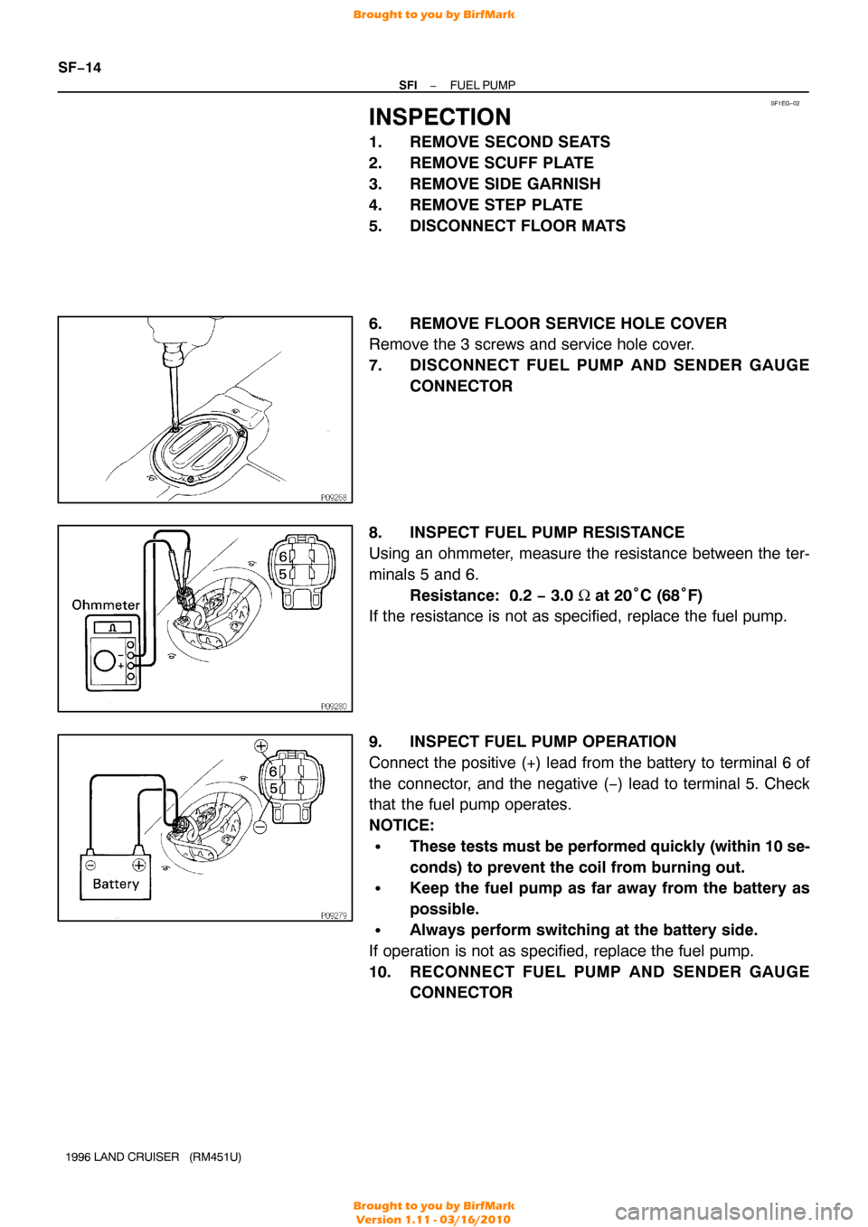
6. REMOVE FLOOR SERVICE HOLE COVER
Remove the 3 screws and service hole cover.
7. DISCONNECT FUEL PUMP AND SENDER GAUGE CONNECTOR
8. INSPECT FUEL PUMP RESISTANCE
Using an ohmmeter, measure the resistance between the ter-
minals 5 and 6. Resistance: 0.2 − 3.0 Ω at 20°C (68°F)
If the resistance is not as specified, replace the fuel pump.
9. INSPECT FUEL PUMP OPERATION
Connect the positive (+) lead from the battery to terminal 6 of
the connector, and the negative ( −) lead to terminal 5. Check
that the fuel pump operates.
NOTICE:
�These tests must be performed quickly (within 10 se-
conds) to prevent the coil from burning out.
�Keep the fuel pump as far away from the battery as
possible.
�Always perform switching at the battery side.
If operation is not as specified, replace the fuel pump.
10. RECONNECT FUEL PUMP AND SENDER GAUGE CONNECTOR
Brought to you by BirfMark
Brought to you by BirfMark
Version 1.11 - 03/16/2010
Page 1200 of 1399
−
SFI FUEL PUMP
SF−15
1996 LAND CRUISER (RM451U)
11. REINSTALL FLOOR SERVICE HOLE COVER
Install the service hole cover with the 3 screws.
12. REINSTALL FLOOR MATS
13. REINSTALL STEP PLATE
14. REINSTALL SIDE GARNISH
15. REINSTALL SCUFF PLATE
16. REINSTALL SECOND SEATS
Torque: 39 N·m (400 kgf·cm, 29 ft·lbf)
Brought to you by BirfMark
Brought to you by BirfMark
Version 1.11 - 03/16/2010