Page 2267 of 2890
B4M0430
1. CHECK GENERATOR.
1) Idling after warm-up.
2) Measure voltage between generator B terminal and
body.
Connector / Specified voltage:
(F25)—body / 10—15 V
2. CHECK BATTERY TERMINAL.
Check that the positive and negative battery terminals are
firmly fixed.
B4M0431A
3. CHECK INPUT VOLTAGE OF ABS/TCS CONTROL
MODULE.
1) Turn ignition switch OFF.
2) Disconnect connector from ABS/TCS control module.
3) Run the engine at idle.
4) Measure voltage between ABS/TCS control module
connector and body.
Connector & terminal / Specified voltage:
(P5) No. 1—body / 10—15 V
B4M0405A
4. CHECK GROUND CIRCUIT OF ABS/TCS CONTROL
MODULE.
1) Turn ignition switch OFF.
2) Disconnect connector from ABS/TCS control module.
3) Measure resistance between ABS/TCS control module
connector and body.
Connector & terminal / Specified resistance:
(P4) No. 6—body / 1Ωor less
(P5) No. 5—body / 1Ωor less
(P7) No. 15—body / 1Ωor less
56
4-4bBRAKES
8. Diagnostics Chart with Trouble Code
Page 2268 of 2890

H: TROUBLE CODE 43
—FAULTY ENGINE CONTROL MODULE
COMMUNICATION CABLES—
DIAGNOSIS:
�AET communication cable is broken or short circuited.
�AEB communication cable is broken or short circuited.
�AEC communication cable is broken or short circuited.
�Faulty ABS/TCS control module
�Faulty engine control module
TROUBLE SYMPTOM:
�TCS does not operate.
1. Check communication cables.
OK
�
Terminal voltage
remains at 4—5.4 V.
Replace ABS/TCS control module.
�
Terminal voltage
remains at 10—14 V.
Go to step 2.
�
Terminal voltage
remains at2Vorless.
Go to step 4.
Replace ABS/TCS control module.
2. Check harness between ABS/TCS control
module and ECM.
OK
�Not OK
Repair harness.
3. Check ABS/TCS control module internal
circuits.
OK
�Not OK
Replace ABS/TCS control module.
Replace engine control module.
4. Check output voltage of ECM.
Not OK
�OK
6. Check open circuit of harness.
OK Not OK
Replace ABS/TCS control
module.
5. Check body short of harness.
OK
�Not OK
Repair harness/connector.
Replace engine control module.
�
�
�
�
��
�
57
4-4bBRAKES
8. Diagnostics Chart with Trouble Code
Page 2270 of 2890
 Turn ignition switch OFF.
2) Disconnect engine control module.
3) Disconnect ABS/TCS control module.
4) Measure v")
B4M0435A
2. CHECK HARNESS BETWEEN ABS/TCS CONTROL
MODULE AND ENGINE CONTROL MODULE.
1) Turn ignition switch OFF.
2) Disconnect engine control module.
3) Disconnect ABS/TCS control module.
4) Measure voltage between ABS/TCS control module
connector and body.
Connector & terminal / Specified voltage:
(P6) No. 12—body/0V(AET communication
cable)
(P6) No. 5—body/0V(AEB communication
cable)
(P6) No. 14—body/0V(AEC communication
cable)
5) Turn ignition switch ON.
6) Measure voltage between ABS/TCS control module
connector and body.
Connector & terminal / Specified voltage:
(P6) No. 12—body/0V(AET communication
cable)
(P6) No. 5—body/0V(AEB communication
cable)
(P6) No. 14—body/0V(AEC communication
cable)
B4M0434A
3. CHECK ABS/TCS CONTROL MODULE INTERNAL
CIRCUITS.
1) Turn ignition switch OFF.
2) Disconnect engine control module.
3) Connect ABS/TCS control module.
4) Measure voltage between ABS/TCS control module
connector and body.
Connector & terminal / Specified voltage:
(P6) No. 12—body/2Vorless (AET communica-
tion cable)
(P6) No. 5—body/2Vorless (AEB communica-
tion cable)
(P6) No. 14—body/2Vorless (AEC communi-
cation cable)
5) Turn ignition switch ON.
6) Measure voltage between ABS/TCS control module
connector and body.
Connector & terminal / Specified voltage:
(P6) No. 12—body/2Vorless (AET communica-
tion cable)
(P6) No. 5—body/2Vorless (AEB communica-
59
4-4bBRAKES
8. Diagnostics Chart with Trouble Code
Page 2271 of 2890

(P6) No. 14—body/2Vorless (AEC communi-
cation cable)
B4M0740A
4. CHECK OUTPUT VOLTAGE OF ENGINE CONTROL
MODULE.
1) Turn ignition switch OFF.
2) Connect engine control module.
3) Connect")
tion cable)
(P6) No. 14—body/2Vorless (AEC communi-
cation cable)
B4M0740A
4. CHECK OUTPUT VOLTAGE OF ENGINE CONTROL
MODULE.
1) Turn ignition switch OFF.
2) Connect engine control module.
3) Connect ABS/TCS control module.
4) Turn ignition switch ON.
5) Measure voltage between engine control module con-
nector and body.
Connector & terminal / Specified voltage:
(B84) No. 74—body / 4—5.4 V (AET communi-
cation cable)
(B84) No. 73—body / 4—5.4 V (AEB communi-
cation cable)
(B84) No. 47—body / 4—5.4 V (AEC communi-
cation cable)
B4M0438A
5. CHECK BODY SHORT OF HARNESS.
1) Turn ignition switch OFF.
2) Disconnect engine control module.
3) Disconnect ABS/TCS control module.
4) Measure resistance between ABS/TCS control module
connector and body.
Connector & terminal / Specified resistance:
(P6) No. 12—body/1MΩor more (AET commu-
nication cable)
(P6) No. 5—body/1MΩor more (AEB communi-
cation cable)
(P6) No. 14—body/1MΩor more (AEC commu-
nication cable)
60
4-4bBRAKES
8. Diagnostics Chart with Trouble Code
Page 2272 of 2890
B4M0728A
6. CHECK OPEN CIRCUIT OF HARNESS.
1) Turn ignition switch OFF.
2) Disconnect engine control module.
3) Disconnect ABS/TCS control module.
4) Measure resistance between ABS/TCS control module
connector and engine control module connector.
(P6) No. 12—(B84) No. 74 / 1Ωor less (AET commu-
nication
cable)
(P6) No. 5—(B84) No. 73 / 1Ωor less (AEB commu-
nication cable)
(P6) No. 14—(B84) No. 47 / 1Ωor less (AEC com-
munication
cable)
61
4-4bBRAKES
8. Diagnostics Chart with Trouble Code
Page 2289 of 2890
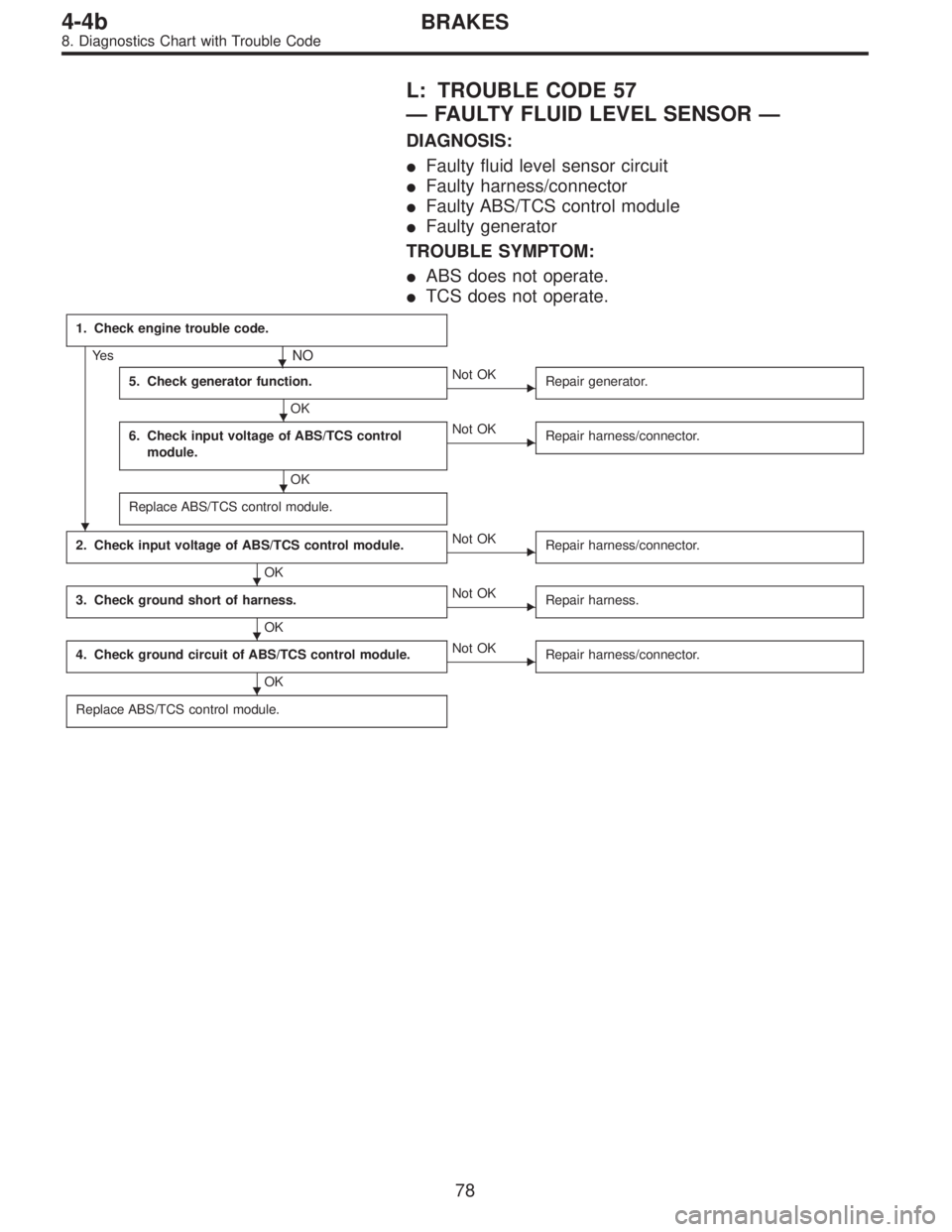
L: TROUBLE CODE 57
—FAULTY FLUID LEVEL SENSOR—
DIAGNOSIS:
�Faulty fluid level sensor circuit
�Faulty harness/connector
�Faulty ABS/TCS control module
�Faulty generator
TROUBLE SYMPTOM:
�ABS does not operate.
�TCS does not operate.
1. Check engine trouble code.
Ye s�NO
5. Check generator function.
OK
�Not OK
Repair generator.
6. Check input voltage of ABS/TCS control
module.
OK
�Not OK
Repair harness/connector.
Replace ABS/TCS control module.
2. Check input voltage of ABS/TCS control module.
OK
�Not OK
Repair harness/connector.
3. Check ground short of harness.
OK
�Not OK
Repair harness.
4. Check ground circuit of ABS/TCS control module.
OK
�Not OK
Repair harness/connector.
Replace ABS/TCS control module.
�
�
�
�
�
�
78
4-4bBRAKES
8. Diagnostics Chart with Trouble Code
Page 2290 of 2890
B4M0743
1. CHECK ENGINE TROUBLE CODE.
1) Read out engine trouble code.
2) Is trouble code 39 in memory?
B4M0395A
2. CHECK INPUT VOLTAGE OF ABS/TCS CONTROL
MODULE.
1) Turn ignition switch OFF.
2) Disconnect ABS/TCS control module connectors.
3) Turn ignition switch ON, while engine is idling.
4) Measure voltage between ABS/TCS control module
connector and body.
Connector & terminal / Specified voltage:
(P5) No. 1—body / 14.5±0.3 V
79
4-4bBRAKES
8. Diagnostics Chart with Trouble Code
Page 2291 of 2890
 Turn ignition switch OFF.
2) Remove No. 18 fuse from fuse and joint box.
3) Disconnect ABS/TCS control module connectors.
4) Measure resistance between AB")
B4M0733A
3. CHECK GROUND SHORT OF HARNESS.
1) Turn ignition switch OFF.
2) Remove No. 18 fuse from fuse and joint box.
3) Disconnect ABS/TCS control module connectors.
4) Measure resistance between ABS/TCS control module
connector and body.
Connector & terminal / Specified resistance:
(P5) No. 1—body/1MΩor more
B4M0405A
4. CHECK GROUND CIRCUIT OF ABS/TCS CONTROL
MODULE.
1) Turn ignition switch OFF.
2) Disconnect connector from ABS/TCS control module.
3) Measure resistance between ABS/TCS control module
connector and body.
Connector & terminal / Specified resistance:
(P4) No. 6—body / 1Ωor less
(P5) No. 5—body / 1Ωor less
(P7) No. 15—body / 1Ωor less
5. CHECK GENERATOR FUNCTION.
1) When the ignition key is at OFF, check the charge warn-
ing light is off.
2) Turn the key ON and ensure the light comes on.
3) Keep the engine running at idle and ensure the light
goes off.
B4M0473A
B4M0395A
6. CHECK INPUT VOLTAGE OF ABS/TCS CONTROL
MODULE.
1) Turn ignition switch OFF.
2) Disconnect ABS/TCS control module connectors.
3) Turn ignition switch ON.
4) Measure voltage between ABS/TCS control module
connector and body.
Connector & terminal / Specified voltage:
(P7) No. 20—body/2Vorless (Engine OFF)
(P7) No. 20—body / 10—14 V (Engine idling)
(P5) No. 1—body / 10—13 V (Engine OFF)
80
4-4bBRAKES
8. Diagnostics Chart with Trouble Code
 Idling after warm-up.
2) Measure voltage between generator B terminal and
body.
Connector / Specified voltage:
(F25)—body / 10—15 V
2. CHECK BATTERY TERMINAL.
Check")
 Turn ignition switch OFF.
2) Disconnect engine control module.
3) Disconnect ABS/TCS control module.
4) Measure resistance between ABS/TCS control module")
 Read out engine trouble code.
2) Is trouble code 39 in memory?
B4M0395A
2. CHECK INPUT VOLTAGE OF ABS/TCS CONTROL
MODULE.
1) Turn ignition switch OFF.
2) Disco")