Page 300 of 2890
 Remove two screws fixing bracket on fuel pump assem-
bly.
H2M1461A
8) Remove one screw fixing fuel level sensor on bracket.
9) Remove fuel level sensor from fuel pump assembly.
B2M0955A
B:")
H2M1460
7) Remove two screws fixing bracket on fuel pump assem-
bly.
H2M1461A
8) Remove one screw fixing fuel level sensor on bracket.
9) Remove fuel level sensor from fuel pump assembly.
B2M0955A
B: INSTALLATION
CAUTION:
Leave fuel filler cap open when tightening nuts, to pre-
vent fuel from flowing out through fuel delivery and
return pipes. Close fuel filler cap after tightening nuts.
Installation is in the reverse order of removal. Do the fol-
lowing:
(1) Always use new gaskets.
(2) Ensure sealing portion is free from fuel or foreign
particles before installation.
(3) Tighten nuts in numerical sequence shown in Fig-
ure to specified torque.
Tightening torque:
4.4±1.5 N⋅m (0.45±0.15 kg-m, 3.3±1.1 ft-lb)
B2M0968
13. Air Filter (2200 cc AWD Model)
A: REMOVAL AND INSTALLATION
1) Remove canister.
2) Remove two hoses from air filter.
3) Remove flange nut from bracket.
4) Installation is in the reverse order of removal.
16
2-1SERVICE PROCEDURE
12. Fuel Level Sensor (2200 cc AWD Model) - 13. Air Filter (2200 cc AWD Model)
Page 301 of 2890
 Remove two screws fixing bracket on fuel pump assem-
bly.
H2M1461A
8) Remove one screw fixing fuel level sensor on bracket.
9) Remove fuel level sensor from fuel pump assembly.
B2M0955A
B:")
H2M1460
7) Remove two screws fixing bracket on fuel pump assem-
bly.
H2M1461A
8) Remove one screw fixing fuel level sensor on bracket.
9) Remove fuel level sensor from fuel pump assembly.
B2M0955A
B: INSTALLATION
CAUTION:
Leave fuel filler cap open when tightening nuts, to pre-
vent fuel from flowing out through fuel delivery and
return pipes. Close fuel filler cap after tightening nuts.
Installation is in the reverse order of removal. Do the fol-
lowing:
(1) Always use new gaskets.
(2) Ensure sealing portion is free from fuel or foreign
particles before installation.
(3) Tighten nuts in numerical sequence shown in Fig-
ure to specified torque.
Tightening torque:
4.4±1.5 N⋅m (0.45±0.15 kg-m, 3.3±1.1 ft-lb)
B2M0968
13. Air Filter (2200 cc AWD Model)
A: REMOVAL AND INSTALLATION
1) Remove canister.
2) Remove two hoses from air filter.
3) Remove flange nut from bracket.
4) Installation is in the reverse order of removal.
16
2-1SERVICE PROCEDURE
12. Fuel Level Sensor (2200 cc AWD Model) - 13. Air Filter (2200 cc AWD Model)
Page 309 of 2890
G2M0093
4) Connect oil pressure gauge hose to cylinder block.
5) Start the engine, and measure oil pressure.
Oil pressure:
98 kPa (1.0 kg/cm
2,14 psi) or more at 800 rpm
294 kPa (3.0 kg/cm2, 43 psi) or more at 5,000 rpm
CAUTION:
�If oil pressure is out of specification, check oil
pump, oil filter and lubrication line.
�If oil pressure warning light is turned ON and oil
pressure is in specification, replace oil pressure
switch.
NOTE:
The specified data is based on an engine oil temperature
of 80°C (176°F).
6) After measuring oil pressure, install oil pressure switch.
Tightening torque:
25±3 N⋅m (2.5±0.3 kg-m, 18.1±2.2 ft-lb)
7) Install generator and V-belt in the reverse order of
removal, and adjust the V-belt deflection.
8
2-2
6. Engine Oil Pressure
Page 314 of 2890
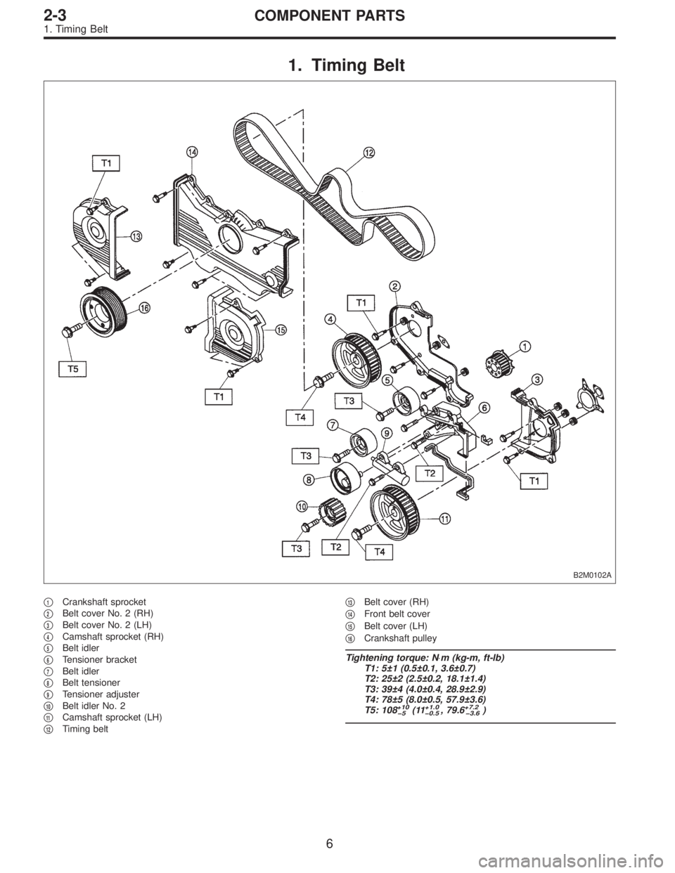
1. Timing Belt
B2M0102A
�1Crankshaft sprocket
�
2Belt cover No. 2 (RH)
�
3Belt cover No. 2 (LH)
�
4Camshaft sprocket (RH)
�
5Belt idler
�
6Tensioner bracket
�
7Belt idler
�
8Belt tensioner
�
9Tensioner adjuster
�
10Belt idler No. 2
�
11Camshaft sprocket (LH)
�
12Timing belt�
13Belt cover (RH)
�
14Front belt cover
�
15Belt cover (LH)
�
16Crankshaft pulley
Tightening torque: N⋅m (kg-m, ft-lb)
T1: 5±1 (0.5±0.1, 3.6±0.7)
T2: 25±2 (2.5±0.2, 18.1±1.4)
T3: 39±4 (4.0±0.4, 28.9±2.9)
T4: 78±5 (8.0±0.5, 57.9±3.6)
T5: 108
+10
�5(11+1.0
�0.5, 79.6+7.2
�3.6)
6
2-3COMPONENT PARTS
1. Timing Belt
Page 315 of 2890
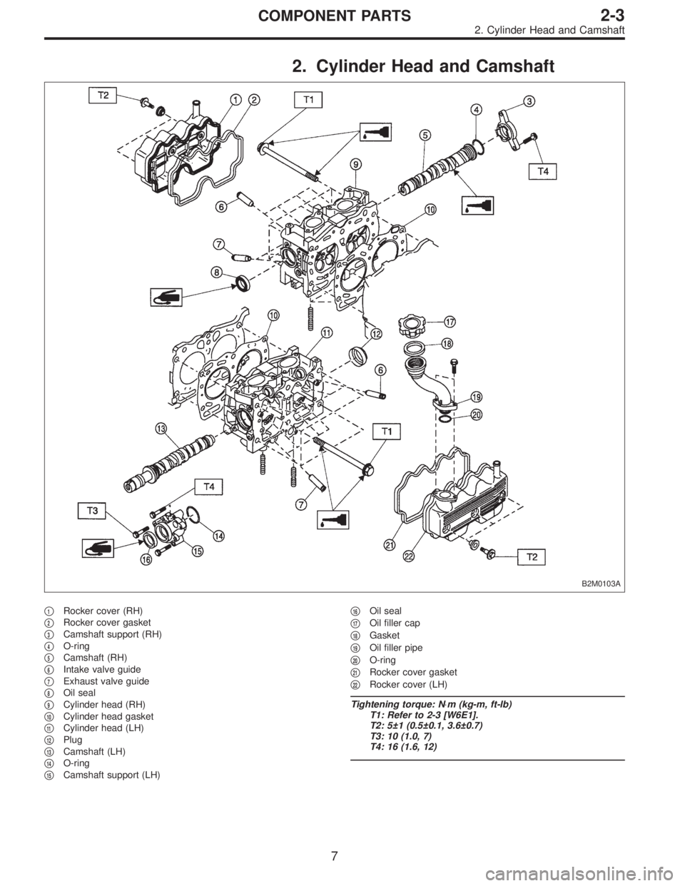
2. Cylinder Head and Camshaft
B2M0103A
�1Rocker cover (RH)
�
2Rocker cover gasket
�
3Camshaft support (RH)
�
4O-ring
�
5Camshaft (RH)
�
6Intake valve guide
�
7Exhaust valve guide
�
8Oil seal
�
9Cylinder head (RH)
�
10Cylinder head gasket
�
11Cylinder head (LH)
�
12Plug
�
13Camshaft (LH)
�
14O-ring
�
15Camshaft support (LH)�
16Oil seal
�
17Oil filler cap
�
18Gasket
�
19Oil filler pipe
�
20O-ring
�
21Rocker cover gasket
�
22Rocker cover (LH)
Tightening torque: N⋅m (kg-m, ft-lb)
T1: Refer to 2-3 [W6E1].
T2: 5±1 (0.5±0.1, 3.6±0.7)
T3: 10 (1.0, 7)
T4: 16 (1.6, 12)
7
2-3COMPONENT PARTS
2. Cylinder Head and Camshaft
Page 316 of 2890
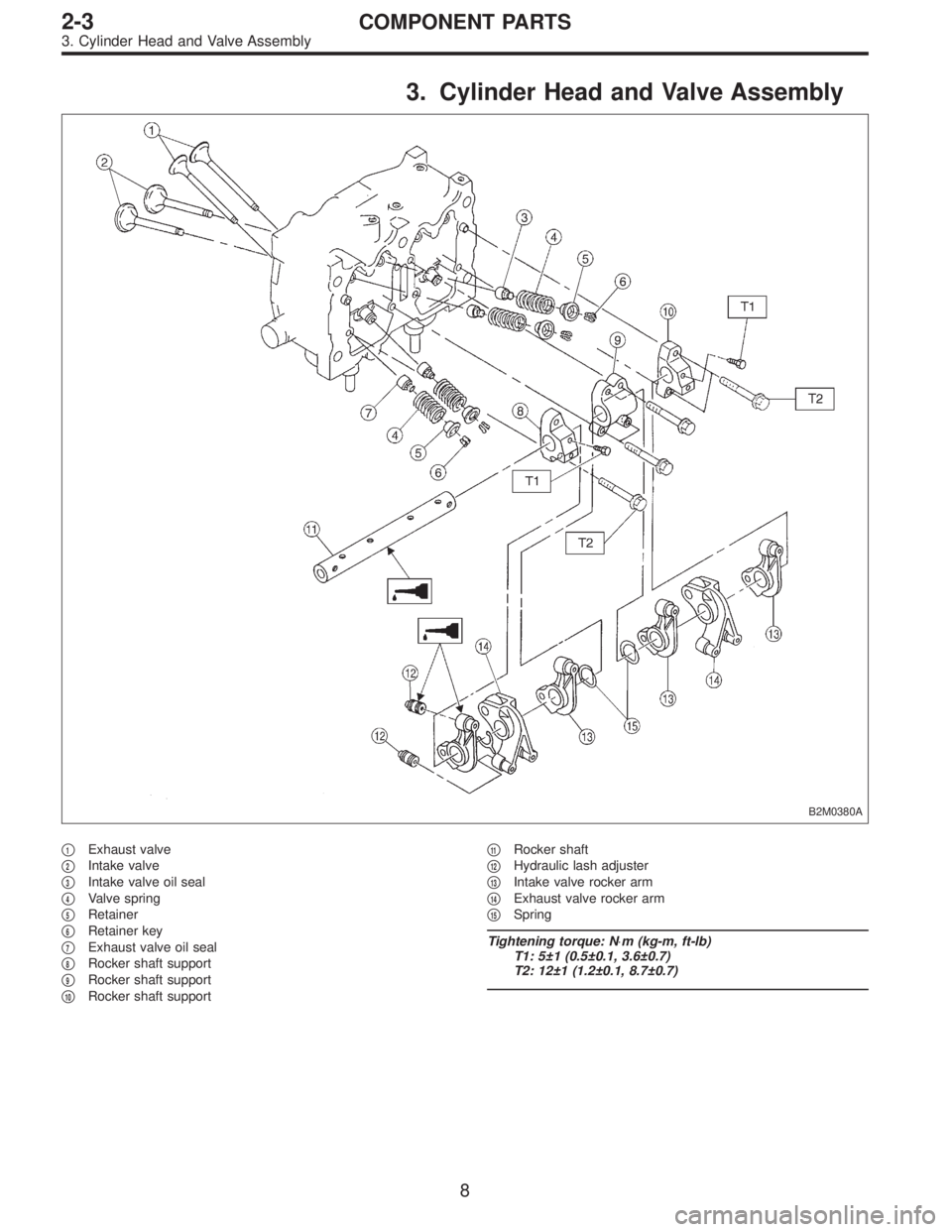
3. Cylinder Head and Valve Assembly
B2M0380A
�1Exhaust valve
�
2Intake valve
�
3Intake valve oil seal
�
4Valve spring
�
5Retainer
�
6Retainer key
�
7Exhaust valve oil seal
�
8Rocker shaft support
�
9Rocker shaft support
�
10Rocker shaft support�
11Rocker shaft
�
12Hydraulic lash adjuster
�
13Intake valve rocker arm
�
14Exhaust valve rocker arm
�
15Spring
Tightening torque: N⋅m (kg-m, ft-lb)
T1: 5±1 (0.5±0.1, 3.6±0.7)
T2: 12±1 (1.2±0.1, 8.7±0.7)
8
2-3COMPONENT PARTS
3. Cylinder Head and Valve Assembly
Page 317 of 2890
4. Cylinder Block
B2M0381A
�1Oil pressure switch
�
2Cylinder block (RH)
�
3Service hole plug
�
4Gasket
�
5Oil separator cover
�
6Water pipe
�
7Oil pump
�
8Front oil seal
�
9Rear oil seal
�
10O-ring
�
11Service hole cover
�
12Cylinder block (LH)
�
13Water pump
�
14Baffle plate
�
15Oil strainer stay
�
16Oil strainer�
17Gasket
�
18Oil pan
�
19Oil drain plug
�
20Gasket
�
21Oil filler pipe
Tightening torque: N⋅m (kg-m, ft-lb)
T1: 5 (0.5, 3.6)
T2: 6.4 (0.65, 4.7)
T3: 10 (1.0, 7)
T4: 25±2 (2.5±0.2, 18.1±1.4)
T5: 47±3 (4.8±0.3, 34.7±2.2)
T6: 69±7 (7.0±0.7, 50.6±5.1)
T7: First 12±2 (1.2±0.2, 8.7±1.4)
Second 12±2 (1.2±0.2, 8.7±1.4)
9
2-3COMPONENT PARTS
4. Cylinder Block
Page 318 of 2890
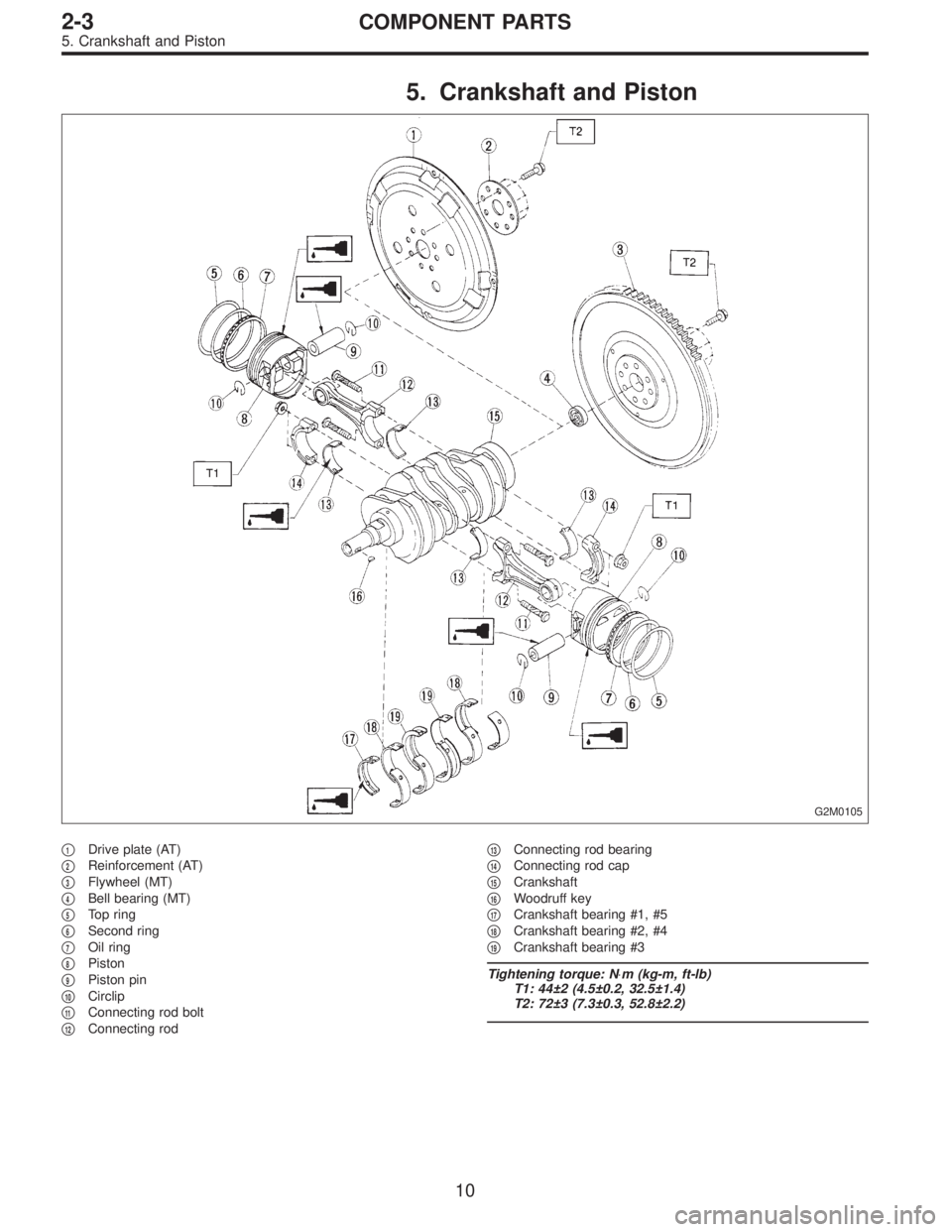
5. Crankshaft and Piston
G2M0105
�1Drive plate (AT)
�
2Reinforcement (AT)
�
3Flywheel (MT)
�
4Bell bearing (MT)
�
5Top ring
�
6Second ring
�
7Oil ring
�
8Piston
�
9Piston pin
�
10Circlip
�
11Connecting rod bolt
�
12Connecting rod�
13Connecting rod bearing
�
14Connecting rod cap
�
15Crankshaft
�
16Woodruff key
�
17Crankshaft bearing #1, #5
�
18Crankshaft bearing #2, #4
�
19Crankshaft bearing #3
Tightening torque: N⋅m (kg-m, ft-lb)
T1: 44±2 (4.5±0.2, 32.5±1.4)
T2: 72±3 (7.3±0.3, 52.8±2.2)
10
2-3COMPONENT PARTS
5. Crankshaft and Piston
 Connect oil pressure gauge hose to cylinder block.
5) Start the engine, and measure oil pressure.
Oil pressure:
98 kPa (1.0 kg/cm
2,14 psi) or more at 800 rpm
294 kPa (3.0 kg/cm2, 43 psi) o")