Page 742 of 2890
G2M0266
1) Open front hood fully, and support with stay.
2) Disconnect battery ground terminal.
3) Remove air intake duct.
G2M0544
4) Disconnect connectors and cables.
(1) Disconnect the following connectors.
�Front oxygen sensor connector
G2M0307
�Transmission harness connector
�Transmission ground terminal
B2M0337
�Neutral position switch connector (MT model)
�Back-up light switch connector (MT model)
G2M0827
�Vehicle speed sensor 2
29
2-11SERVICE PROCEDURE
3. Transmission
Page 750 of 2890
�B
AT model
12. Install shift selector cable to selector lever.
13. Install ATF level gauge guide, and connect ATF cooler hose
to pipe.
AWD model
14. Install propeller shaft.
15. Install exhaust system.
�Heat shield cover [AWD]
�Rear exhaust pipe [AWD]
�Front exhaust pipe
�Center exhaust pipe
16. Install transmission connector holder bracket.
AT model
17. Install ATF level gauge.
18. Connect connectors and cables.
19. Install starter.
20. Install air intake duct.
21. Connect battery ground cable.
22. Fill ATF. [AT]
23. Check selector lever operation. [AT]
24. Take off the vehicle from lift arm.
25. Check the vehicle on the road tester. [AT]
�
�
�
�
�
�
�
�
�
37
2-11SERVICE PROCEDURE
3. Transmission
Page 757 of 2890
G2M0266
20) Install air intake duct.
21) Connect battery ground cable.
22) Fill ATF. (AT model)
23) Check selector lever operation. (AT model)
24) Take off vehicle from lift arms.
25) Check the vehicle on road tester. (AT model)
44
2-11SERVICE PROCEDURE
3. Transmission
Page 1280 of 2890

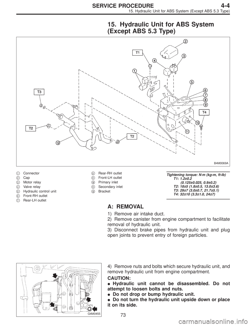
15. Hydraulic Unit for ABS System
(Except ABS 5.3 Type)
B4M0069A
�1Connector
�
2Cap
�
3Motor relay
�
4Valve relay
�
5Hydraulic control unit
�
6Front-RH outlet
�
7Rear-LH outlet�
8Rear-RH outlet
�
9Front-LH outlet
�
10Primary inlet
�
11Secondary inlet
�
12Bracket
Tightening torque: N⋅m (kg-m, ft-lb)
T1: 1.2±0.2
(0.125±0.025, 0.9±0.2)
T2: 18±5 (1.8±0.5, 13.0±3.6)
T3: 29±7 (3.0±0.7, 21.7±5.1)
T4: 32±10 (3.3±1.0, 24±7)
A: REMOVAL
1) Remove air intake duct.
2) Remove canister from engine compartment to facilitate
removal of hydraulic unit.
3) Disconnect brake pipes from hydraulic unit and plug
open joints to prevent entry of foreign particles.
G4M0455
4) Remove nuts and bolts which secure hydraulic unit, and
remove hydraulic unit from engine compartment.
CAUTION:
�Hydraulic unit cannot be disassembled. Do not
attempt to loosen bolts and nuts.
�Do not drop or bump hydraulic unit.
�Do not turn the hydraulic unit upside down or place
it on its side.
73
4-4SERVICE PROCEDURE
15. Hydraulic Unit for ABS System (Except ABS 5.3 Type)
Page 1302 of 2890
20. Hydraulic Unit for ABS/TCS System
B4M0707A
�1ABS/TCS hydraulic
control unit
�
2Rear-RH outlet
�
3Front-LH outlet
�
4Front-RH outlet
�
5Rear-LH outlet
�
6Secondary inlet
�
7Primary inlet�
8Secondary suction line
�
9Primary suction line
�
10Bumper
�
11Bracket
�
12Pressure switch
�
13Valve relay
�
14Motor relay
Tightening torque: N⋅m (kg-m, ft-lb)
T1: 7.4±2.0 (0.75±0.2, 5.4±1.4)
T2: 29±7 (3.0±0.7, 21.7±5.1)
T3: 32±10 (3.3±1.0, 24±7)
T4: 38±10 (3.8±1.0, 27±7)
T5: 3.1±1 (0.32±0.1, 2.3±0.7)
A: REMOVAL
1) Disconnect ground cable from battery.
2) Remove canister, air intake and air cleaner case duct
from engine compartment to facilitate removal of hydraulic
unit.
3) Disconnect brake pipes from hydraulic unit.
CAUTION:
Wrap brake pipes with vinyl bag to avoid spilling brake
fluid on vehicle body.
4) Disconnect connector from hydraulic unit.
93
4-4SERVICE PROCEDURE
20. Hydraulic Unit for ABS/TCS System
Page 1316 of 2890
B4M0628
G: INSTALLATION
1) Install hydraulic unit and bracket.
Tightening torque:
32±7 N⋅m (3.3±0.7 kg-m, 23.9±5.1 ft-lb)
2) Connect brake pipes to their correct hydraulic unit con-
nections.
3) Connect connector to hydraulic unit.
4) Install canister.
5) Install air cleaner case.
6) Install air intake duct.
7) Connect ground cable to battery.
CAUTION:
Cover relay securely with rubber boot.
21. ABS/TCS Control Module
A: REMOVAL
1) Disconnect ground cable from battery.
2) Remove floor mat located under lower right side of front
seat.
B4M0643A
3) Remove screw which secure ABS/TCS control module
from the body.
4) Disconnect connector from ABS/TCS control module.
B: INSPECTION
Check that connector is connected correctly and that con-
nector terminal sliding resistance is correct.
107
4-4SERVICE PROCEDURE
20. Hydraulic Unit for ABS/TCS System - 21. ABS/TCS Control Module
Page 1317 of 2890
B4M0628
G: INSTALLATION
1) Install hydraulic unit and bracket.
Tightening torque:
32±7 N⋅m (3.3±0.7 kg-m, 23.9±5.1 ft-lb)
2) Connect brake pipes to their correct hydraulic unit con-
nections.
3) Connect connector to hydraulic unit.
4) Install canister.
5) Install air cleaner case.
6) Install air intake duct.
7) Connect ground cable to battery.
CAUTION:
Cover relay securely with rubber boot.
21. ABS/TCS Control Module
A: REMOVAL
1) Disconnect ground cable from battery.
2) Remove floor mat located under lower right side of front
seat.
B4M0643A
3) Remove screw which secure ABS/TCS control module
from the body.
4) Disconnect connector from ABS/TCS control module.
B: INSPECTION
Check that connector is connected correctly and that con-
nector terminal sliding resistance is correct.
107
4-4SERVICE PROCEDURE
20. Hydraulic Unit for ABS/TCS System - 21. ABS/TCS Control Module
Page 1319 of 2890
22. Hydraulic Unit for ABS System
(ABS 5.3 Type)
B4M0994A
�1Hydraulic control unit
�
2Damper
�
3Stud bolt
�
4Rear-RH outlet
�
5Rear-LH outlet
�
6Secondary inlet
�
7Primary inlet
�
8Front-LH outlet�
9Front-RH outlet
�
10Cable clip
�
11Bracket
�
12Relay box
�
13Motor relay
�
14Valve relay
�
15Cap
�
16Connector bracket
Tightening torque: N⋅m (kg-m, ft-lb)
T1: 18±5 (1.8±0.5, 13.0±3.6)
T2: 29±7 (3.0±0.7, 21.7±5.1)
T3: 32±10 (3.3±1.0, 24±7)
A: REMOVAL
1. HYDRAULIC UNIT
1) Disconnect ground cable from battery.
2) Remove air intake duct and canister from engine com-
partment to facilitate removal of hydraulic unit.
3) Disconnect connector from hydraulic unit.
4) Unlock cable clip.
5) Disconnect brake pipes from hydraulic unit.
CAUTION:
Wrap brake pipes with vinyl bag to avoid spilling brake
fluid on vehicle body.
109
4-4SERVICE PROCEDURE
22. Hydraulic Unit for ABS System (ABS 5.3 Type)