Page 123 of 2189

Valve Clearance
Adjustment
NOTE:
. Valves should be adjusted only when the cylindsrhead temperature is less than 100"F (38"C).
. After adjusting, retorque the crankshaft pulley bolt(see page 6-16).
1, Remove the cylinder head cover.
NOTE; Refer to page e46 when installing the cytinderhead cover.
2. Remove the upper cover (see page 6-19).
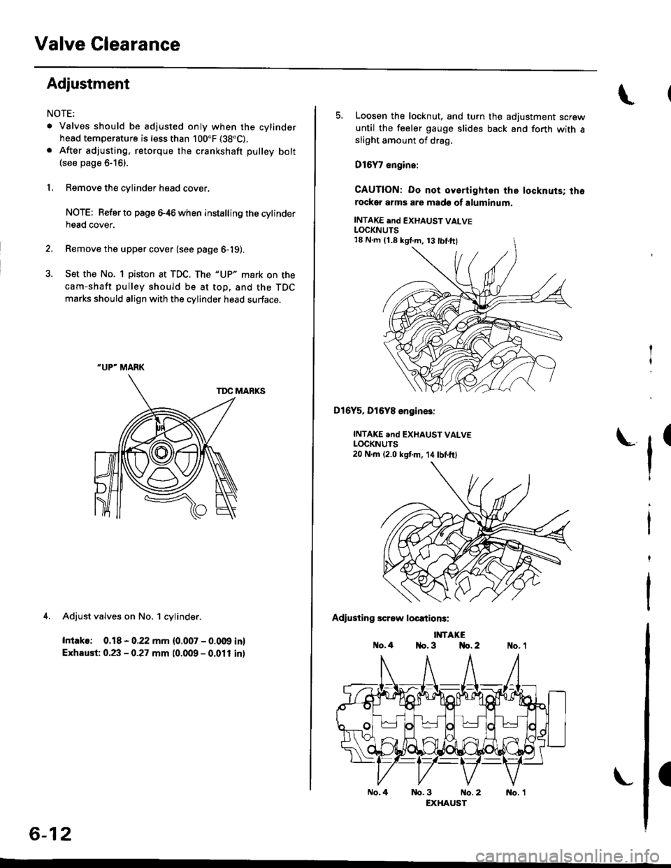
3. Set the No. 1 piston at TDC. The "UP" mark on the
cam-shaft pulley should be at top, and the TDC
marks should align with the cylinder head surface.
TDC MARKS
4. Adjust valves on No, 1 cylinder.
Intako: 0.18 - 0.22 mm {0.007 - 0.009 in}
Exhaust: 0.23 - 0.27 mm (0.009 - 0.011 inl
"UP" MARK
6-12
No.4
5. Loosen the locknut, and turn the adjustment screwuntil the feeler gauge slides back and forth with asliOht amount of drag,
D16Y7 engin.:
CAUTION: Do not oyertighlen the locknuts; thorockor arms are made of aluminum.
INTAKE end EXHAUST VALVELOCKNUTS
Dl6Y5, Dl6Y8 engin€3:
INTAKE .nd EXHAUST VALVELOCKNUTS20 N.m 12.0 kstm, 14lbtft)
Adiusting screw locations:
IMTAKEo.4 1{o. 3 No. 2
tr'
(
nb.3 No.2 No. 1EXHAUST
18 N.m (1.8 kgI.m, 13 tbl.ftl
Page 141 of 2189

Cylinder HeadRocker Arms
18.
19.
21.
22.
Removal (cont'd)
Remove the timing belt {see page 6-19).
Remove the camshaft pulley and back cover,
CAMSHAFTPULLEYClean when installing.
6x1.0mm8 x 1.25 mm37 N.m (3.8 kgf.m,21 tbtlrlApply engine oilto thebolt threads.
Remove the exhaust manifold {see pages 9-6 and 9_7).
Remove the intake manifold (see pages 9-2 thru 4).
Remove the cylinder head bolts, then remove thecylinder head.
CAUTION: To pr€vent warpage, unsclew lhe bohsin sequonce 1/3 turn at a time; rgpeat tho sequenceuntil all bolts are loosened.
CYLINDER HEAD BOLTS LOOSENING SEOUENGE:
6-30
Removal
1. Loosen the adjusting screws.
2. Unscrew the camshaft holder bolts, then,removethe rocker arm assembly.
NOTE:
a Unscrew the camshaft holder bolts two turns at at,me, in a crisscross pattern, to prevent damao_ing the valves or rocker arm assembly.. When removing the rocker arm assembly, do notremove the camshaft holder bolts. The bolts willkeep the camshaft holders, the springs and therocker arms on the shaft.
CAMSHAFT HOLDER BOLTS LOOSENINGSEOUENCE:
\(
ADJUSTING SCREWS
Page 167 of 2189

Valve Glearance
Adjustment
NOTE:
. Valves should be adjusted only when the cylinder
head temperaturs is less than 100'F (38'C)'
. After adjusting, retorque the crankshaft pulley bolt to
177 N.m (18.0 kgf'm, 130 lbt'ft)
1. Remove the cylinder head cover'
NOTE: Refer to page G86 when installing the cylin-
der head cover.
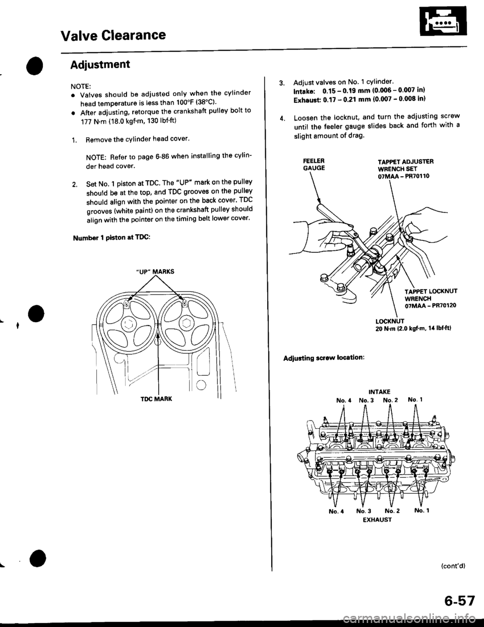
2. Set No. 1 pi$on at TDC. The "UP" mark on the pullsy
should be at the top, and TDC grooves on the pulley
should align with the pointer on the back cover' TDC
grooves {white paint) on the crankshaft pulley should
align with the pointer on the timing belt lower cover'
Number I Piston at TDC:
4.
Adjust valves on No. 1 cylinder.
lntako: 0.15 - 0.19 mm {0'006 - 0.007 in)
ExhaGt 0.17 - 0.21 mm {0'007 - 0 008 inl
Loosen the locknut, and turn the adjusting screw
until the feeler gauge slides back and forth with a
slight amount of drag.
TAPPET ADJUSTERWFENCH SET07MM - PR70110
TAPPET LOCKNUTWRENCH07MAA - PR70120
Adiusting sclaw location:
LOCKNUT20 N.m {2.0 kgf'm, lil lbt'ftl
(cont'd)
6-57