Page 1764 of 2189
Troubleshooting
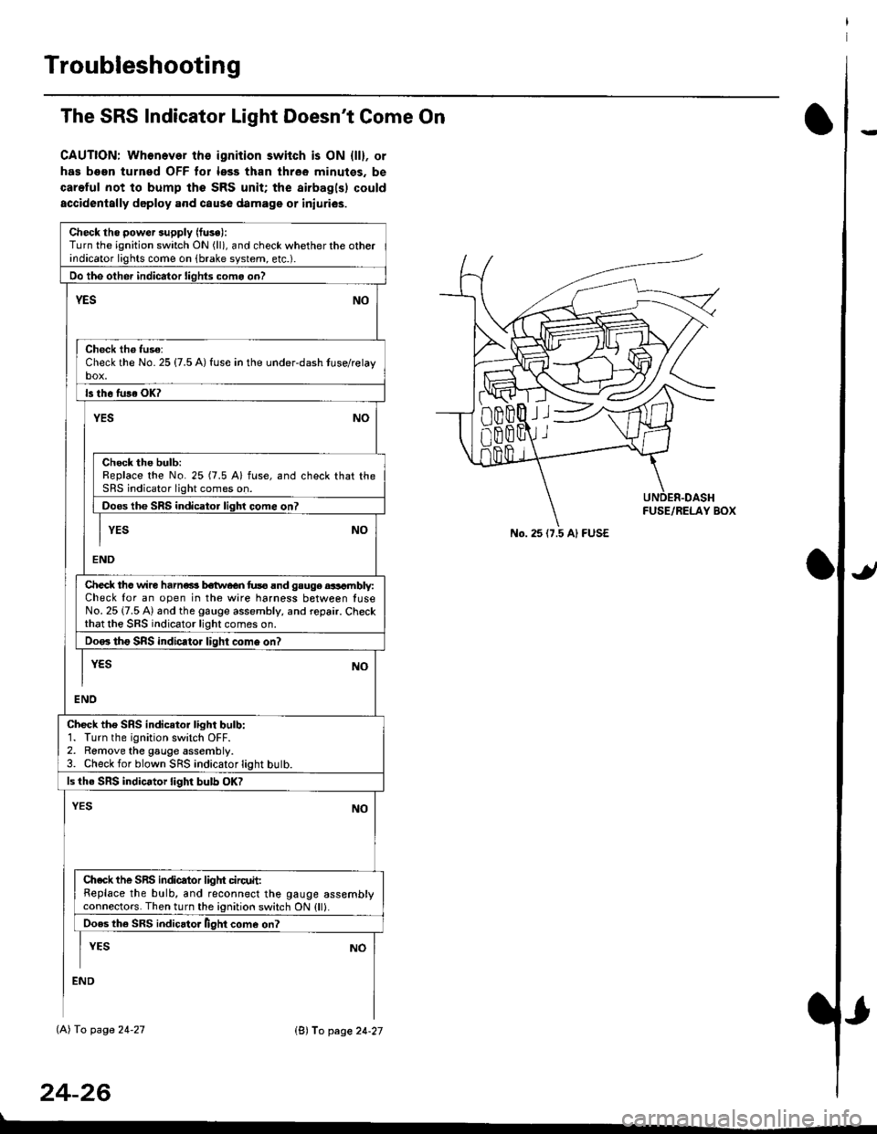
The SRS Indicator Light Doesn't Come On
CAUTION: Whonever ths ignition switch is ON {ll}, or
has been turned OFF tor less than three minutes. be
careful not to bump the SRS unit; the airbagls) could
accidentally deploy .nd caus6 damage or iniuri€s.
Check tho pow€r supply (fuse):
Turn the ignition switch ON (ll), and check whether the otherindicator lights come on (brake system, etc.).
Oo the other indicator liohts como on?
YESNO
Check th6 fuso:Check the No. 25 {7.5 A) fuse in the under-dash tuse/relayb"t
ls th6 tu36 OK?
NOYES
Check the bulb:Replace the No. 25 (7.5 A) fuse, and check that theSRS indicator light comes on.
Doos the SRS indicator liqhl come on7
I YES No
END
Check tho wire harns b€twecn fus6 and gauge aasambly:Check for an open in the wire harness between luseNo. 25 {7.5 A) and the gauge assembly, and repair. Checkthat the SRS indicator light comes on.
Doo. tho SRS indic.tor light como on?
I yEs No
I
END
Check tho SRS indicator light bulb:1. Turn the ignition switch OFF.2. Remove the gauge assembly.3. Check for blown SRS indicator light butb.
ls the SRS indicator light bulb OK?
NOYES
Ch.ck the SnS indicator liglrt circuit:Replace the bulb, and reconnect the gauge assemblyconnectors. Then turn the ignition switch ON {ll}.
Ooes th6 SRS indicato. llght come on?
I YEs No
:ND
lAl To page 24-27
24-26
lB'J fo page 24-27
))
No. 25 (7.5 Al FUSE
Page 1765 of 2189
)
From page 24-26
(A)
From page 24-26
(B)DASHBOARD WIRE HARNESS
5P CONNECTOR
It
MAIN WIRE HARNESS2,rP CONNECTOR
DASHAOARD WIREHARNESS 2irPCONNECTOR
c41 1
(cont'd)
24-27
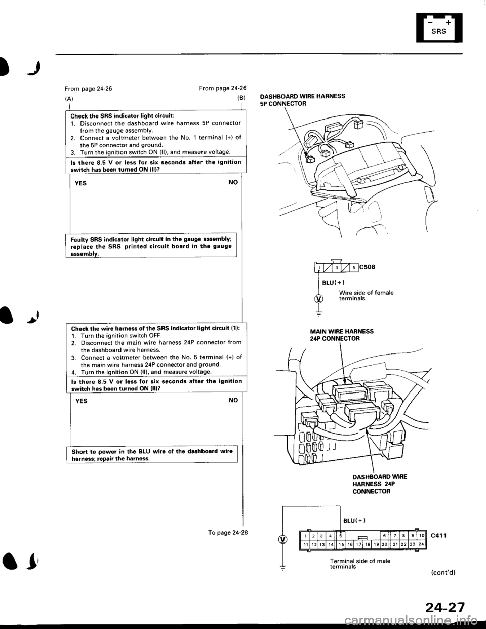
check the sRs indicator light circuit:1. Disconnect the dashboard wire harness 5P connector
from the gauge assembly.2. Connect a voltmeter between the No. 1 terminal (+) of
the 5P connector and ground.
3. T!rn the ignition switch ON 1ll), and meas!re voltage.
ls there 8.5 V or loss lor six seconds atter the ignition
swilch has been turned ON {lll?
YESNO
Faulty SRS indicator light circuit in the gauge e$embly;
replace the SRS printed circuit boa.d in tho gauge
ass€mblY.
Check the wire harness otthe SRS indicator light circuil {1):'1. Turn the ignition switch OFF.2. Disconnect the main wire harness 24P connector from
the dashboard wire harness.
3. Connect a voltmeter between the No. 5 terminal {+) of
the main wire harness 24P connector and 9round4. Turn the ignition ON (ll), and measure voltage.
ls thore 8.5 V or lcss tor tix second3 .Itor the ignition
switch has b6en turned ON lll)?
YESNO
Short to oower in the BLU wire ol the dashboald wiroharness; rgpaii the ham€ss.
To page 24-28
ar
Page 1769 of 2189
)
From page 24'30(B)
To page 24-33
5P CONNECTOF
mcsogA#
I Btu lYEtWire side of fomale
lUUpeA Wtng terminals
OASHBOARD WIRE HARNESS
It
Wire side ol femaletetmtnals
SRS MAIN HARNESSlAP CONNECTOR
(D)
To page 24'33
DASHBOARD WIRE HARNESS5P CONNECTOR
(cont'd)
DASHBOARD WINE HARNESS
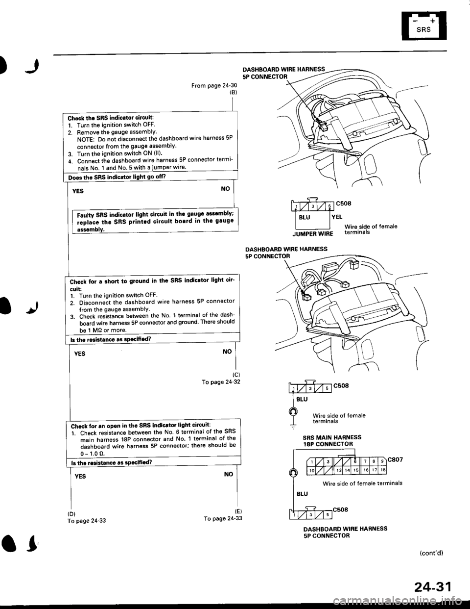
Check th. SBS indicatot circuit:
1. Turn the ignition switch OFF.
2. Removo the gauge assembly.
NoTE: Do n;t disconnect the dashboard wire harness 5P
connsctor lrom the gauge assembly
3. Turn the ignition switch ON (ll).
4. Connect th€ dashboard wire harness 5P connector termi-
nals No. 1 and No.5with a jumperwiro.
Doo3th. SRS indicstor light go offf
Fautty SRS indicltot light citouit in th. grugc a$cmbly;
rcpl.ce the SRS ptint.d cilcuit boaJd in thc gtugs
b€ 1 MO or more.
Ch.ck tor a ihort to glound in th. SRS IndioltoJ light cir'
cuit:1. Turn the ignition switch OFF.
2. Disconnect the dashboard wire harness 5P connector
from the gauge assemblY
3. Check resistance between the No. 1 terminal of the dash
board wire harness 5P connector and ground. There should
Ch.ck to. an opon in tho SnS indic.tor light circuh:
1. Ch6ck resistanc€ between the No 6 terminal of the SRS
msin harness 18P connector and No. 'l terminal ot the
dashboard wire harness 5P connector; there should be
Wire side ot female terminals
24-31
or
Page 1773 of 2189
)
From page 24-34(A)
SRS MAIN HARNESS I8P CONNECTOR
(B)
To page 24-36
1)
Wire sidg of lemale terminals
DASHBOARD WIRE HARNESS
5P CONNECTOR
ic)To page 21'31
DASHBOARD WIRE HARNESS
5P CONNECTOR
c508
t of lemale
(cont'd)
24-35
SRS MAIN HARNESS
Chock iho SRS unit:
Connect the SRS main harness 18P connector terminals No'
6 and No. 3 with a jumper wire and backprobe
Doos tho SRS indicator light go off?
Faulw SRS unit or poot co tact at the SRS ftain htmes!
18P connoctor; chack the connagtot.
ll tha connoctor b OK roplaca lho SRS unit'
oid tu3e No. 23 t10 A) blow?
Chcck for e short to ground in th. SRS indicator lighi cir-
cuh:1. Turn the ignition switch OFF
2. Disconneit the dashboard wire harness 5P connector
from the gauge assembly.
3. Check res-ista;ce between the No l terminai ofth€dash-
board wire harness 5P connector and ground There
should be '1 M0 or more.
Short to glound in th. gaugs aslomblY; .6plac' th' gtug'
JUMPEB WIRE
o!
Page 1774 of 2189
Troubleshooting
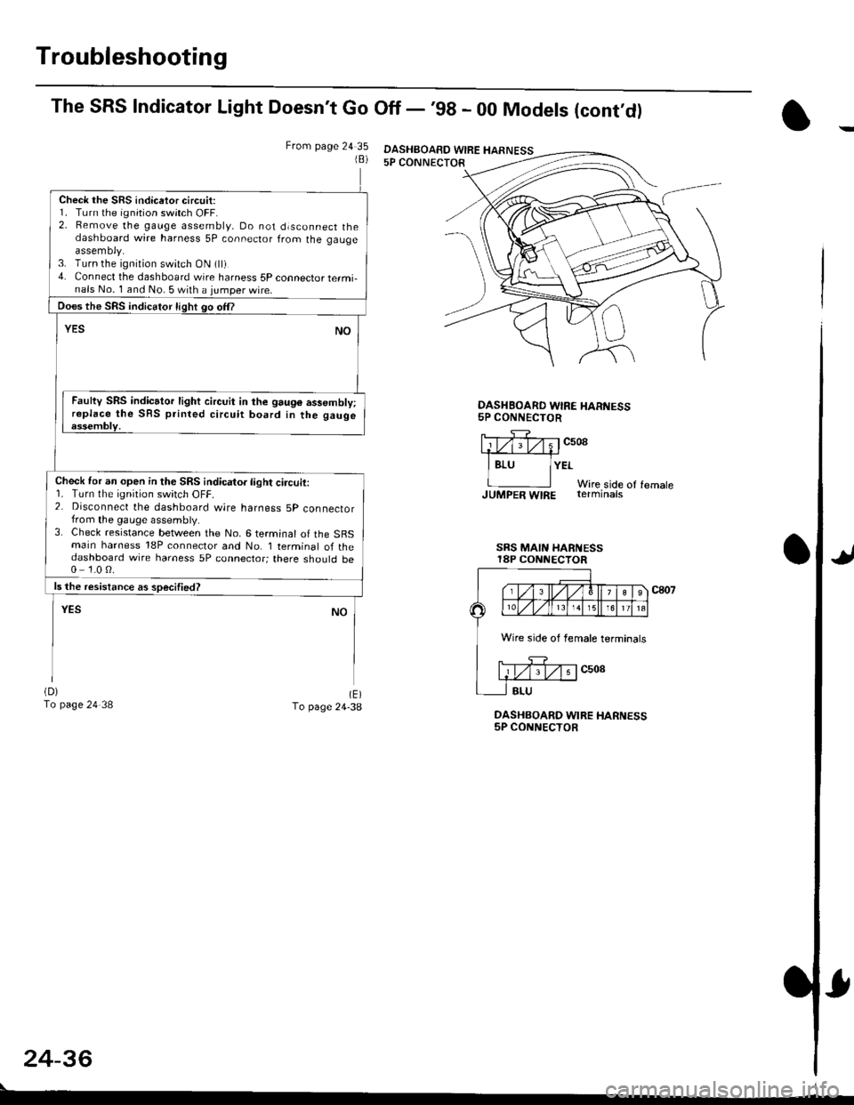
The SRS Indicator Light Doesn't Go Off - '98 - 00 Models (cont,dl
From page 24 351B)
Check the SRS indicetor circuit:1. Turn the ignition switch OFF.2. Bemove the gauge assembly, Do not dlsconnect thedashboard wire harness 5P connector from the gaugeassemoly.3. Turn the ignition switch ON (ll)4. Connect the dashboard wire harness 5P connector termi-nals No. 1 and No. 5 with a jumper wire.
Does the SRS indicator light go om
YESNO
Faulty SRS indicator light circuit in the 9au96 assembly;replace the SRS printed circuit board in the gaugeessembly.
Check for an open in the SRS indicator light circuit:r. rurn rne rqnrton swrtch ut-t-.2. Disconnect the dashboard wire harness 5p connectorfrom the gauge assembly.3. Check resistance between the No. 6 terminal of the SBSmain harness 18P connector and No. I terminal of thedashboard wire harness 5P connector; there should be0 1.0 0.
ls the resistance as soecified?
NOYES
(D)
To page 24 38(E)To page 24-38DASHBOARD WIRE HARNESS5P CONNECTOR
OASHBOARD WIRE HAR'{ESS5P CONNECTOR
llTf;rv;1c508.1#
I Bru lYErWire side of femaleJUMpER WIRE rerminats
SRS MAIN HARi{ESSI8P CONNECTOR
c807
24-36
DASHBOAED WIRE HARNESS
Wire side of female terminals
Page 1823 of 2189
How To Use This Manual
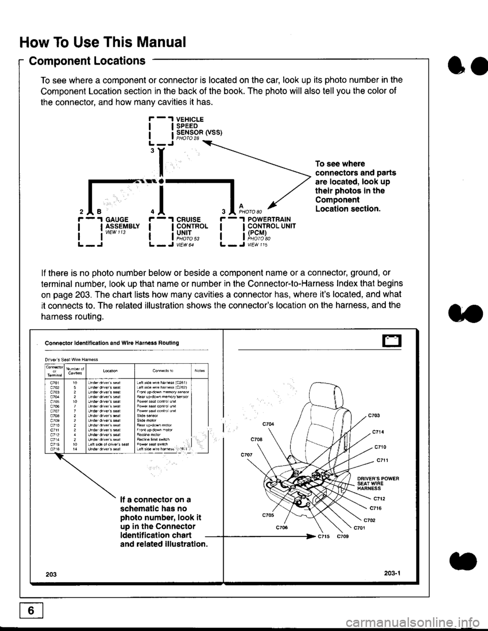
Component Locations
To see where a component or connector is located on the car, look up its photo number in the
Component Location section in the back of the book. The photo will also tell you the color of
the connector, and how many cavities it has.
To see where
connectors and parts
are located, look up
their photos in the
Component
Location section.
I
I
3
r - 1 GAUGE
| | I_S-9_EIBLY
lt''""'
r - 1 cRUtsE
! !fi':*
r - 1 POWERTRAIN
I I CONTROL UNrr
a i[i9#r,
lf there is no photo number below or beside a component name or a connector, ground, or
terminal number, look up that name or number in the Connector-to-Harness Index that begins
on page 203. The chart lists how many cavities a connector has, where it's located, and what
it connects to. The related illustration shows the connector's location on the harness, and the
harness routing.
Connactor ldontlticallon and Wke Harness Rouling
DFIVEF'S POWERSEAT WIAEHAFNESS
It a connector on a
schematic has no
photo number, look it
up in the Connector
ldentilication chart
c712
c7t6
c702c701
and related illustration.
203203.1
Drlvor s Sea! wne Harn€ss
Lefts'd.Hrc hatu$ 1c2611Loft s'd. src hamass 1c262)
F6ar up.dow^ n.morykisor
l
E
oo
Page 1825 of 2189
How To Use This Manual
Symbols
oo
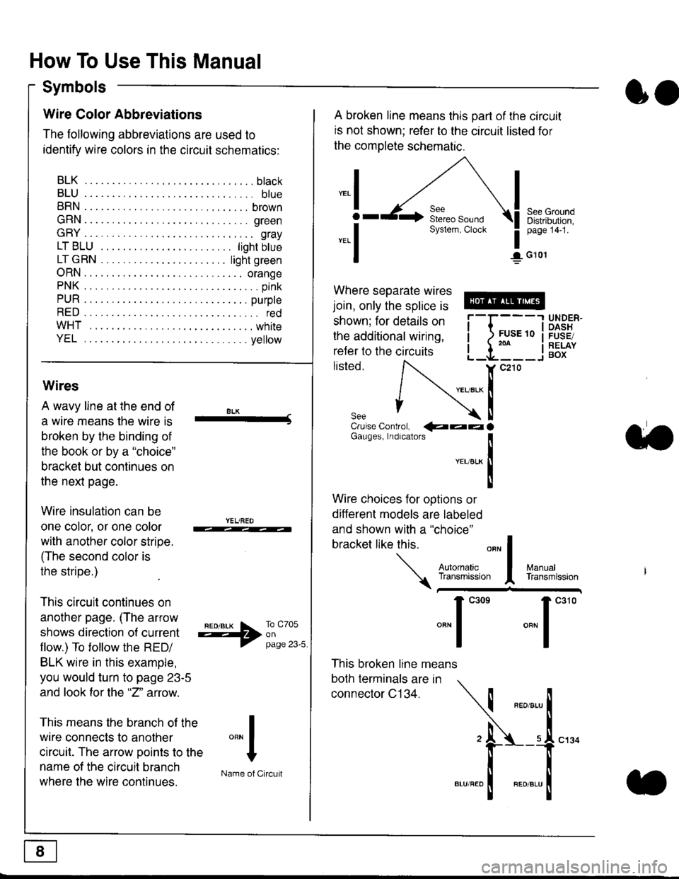
Wire Color Abbreviations
The following abbreviations are used to
identify wire colors in the circuit schematics:
BLK.... .........b|ack
BLU.... ......... blue
BRN.... ,....... brown
GRN.... ........ green
GRY.... ......,.. gray
LTBLU . .....lightbtue
LTGRN. ....lightgreen
ORN.... ....... orange
PNK .... .......,.. pink
PUR .... ........ purple
RED .... .......... red
WHT... .........white
YEL .... ........ yellow
A broken line means this part of the circuit
is not shown; refer to the circuit listed for
the complete schematic.
"ral
o
-.1
See GroundDistribution,page 141.
I G101
Where separate wires
join, only the splice is
shown; for details on
the additional wiring,
refer to the circuits
listed.ili::i
{[
UNDER-OASHFUSE/RELAYBOX
Wires
A wavy line at the end of
a wire means lhe wire is
broken by the binding of
the book or by a "choice"
bracket but continues on
the next page.
Wire insulation can be
one color, or one color
with another color stripe.
(The second color is
the stripe.)
This circuit continues on
another page. (The arrow
shows direction o{ current
flow.) To tollow the RED/
BLK wire in this example,
you would turn to page 23-5
and look for the "2" anow.
This means the branch of the
wire connects to another
circuit. The arrow Doints to the
name of the circuit branch
where the wire continues.
8LK-Cruise Control, €�aaaGauges, Indrcalors
!YEUsLK
Ttl
Wire choices for options or
different models are labeled
and shown with a "choice"
bracket like this.
This broken line means
both terminals are in
connector C134.
a.
+##l:i""lManuallransmission
ryil;::,
.""1
""'
"""1".'0
I
""^l
:-lName of Circuit
Page 1826 of 2189
Connectors - "C"
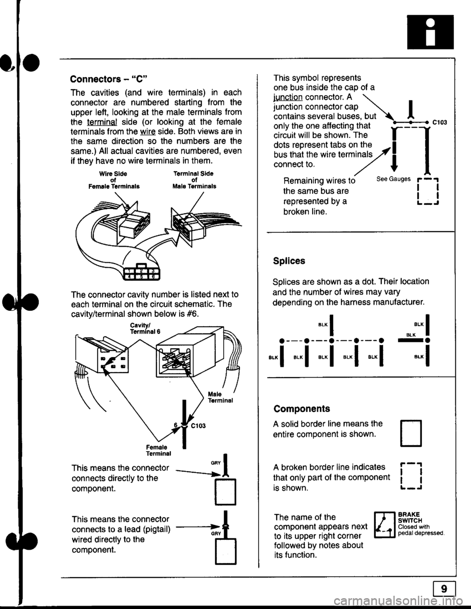
The cavities (and wire terminals) in each
connector are numbered starting from the
upper left, looking at the male terminals trom
the terminal side (or looking at the female
lerminals f rom the wire side. Both views are in
the same direction so the numbers are the
same.) All actual cavities are numbered, even
if they have no wire terminals in them.
Terminal SldeolMale Tsrminals
{
T
_A
Wlre SldeotFemalg Trrmlnala
The connector cavity number is listed next to
each terminal on the circuit schematic. The
cavity/terminal shown below is #6.
Terminal
This means the connector
connects directly to the
componenr.
This means the connector
connects to a lead (pigtail)
wired directly to the
component.
Cavlty/Termlnsl 6
only the one affecting that
ciriuit will be shown. The f
--f
!!*!"*F"#fi5'�;,Hy4
I
Remaining wires to
the same bus are
represented by a
broken line.
The name of the
component appears next
to its upper right corner
followed by notes about
its function.
This symbol represents
one bus inside the cao of a
iunction connector. A \
lr"ctb. connectorcap |contains several buses, but Ac103
tl
tl
*-
I ",.-"* I
a---a---a--- a--- o -a
*"1 *-l *-l *-l *"1 *-l
See Gauges
Splices
Solices are shown as a dot. Their location
and the number of wires may vary
depending on the harness manufacturer.
Components
A solid border line means the
entire component is shown.
A broken border line indicales
that only part of the component
is shown.
t_J
ll
ll
BRAXEswtTcHClosed wilhpedaldepressed.