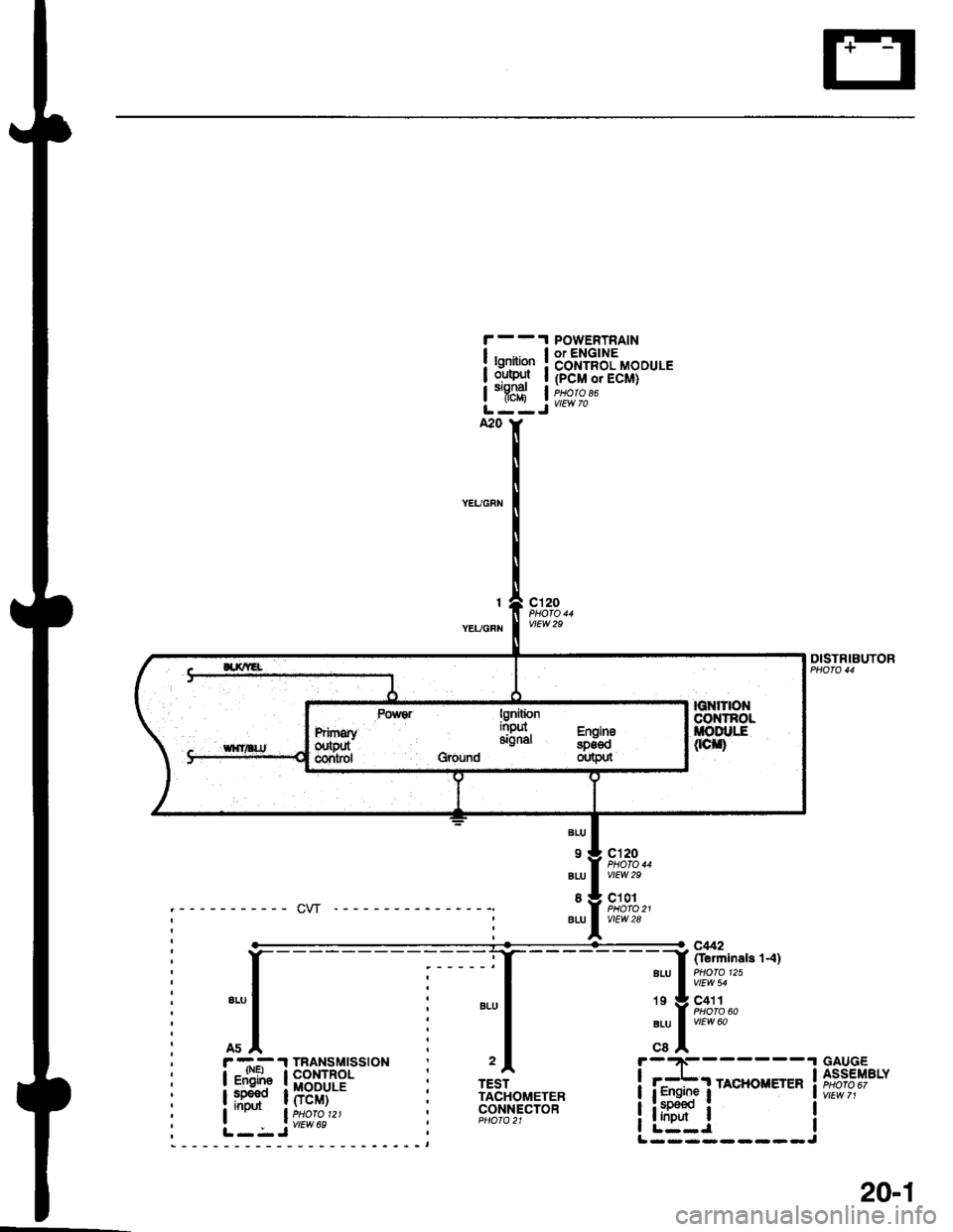
1996 HONDA CIVIC Gauge connector
[x] Cancel search: Gauge connectorPage 1840 of 2189

Ground-to-Components I ndex
f.,lONOTE: All ground wires are BLK unless otherwise noted.
GroundPageComponents or Circuit Grounded
Battery (BLKYEL)
Steering pump bracket
t+-rg ITransmission housing
l
G101
(-1)
G101
(-2)
14-2
and
14-3
ano
14-1
Powertrain or engine control module (PG1 and pG2 are BLK: LG1 and LG2 are
BRN/BLK), EGR control solenoid valve (CW, EGR valve and lift sensor (Dt6yS enginewith M,/T), Engine coolant temperature switch, pGM-Fl main relay, power steeringpressure switch (USA), Primary HO2S (D16Y5 engine with l\/,/T), Vehicle speed sensor,VTEC pressure switch (D16Y5/D16Y8 engines), CKF sensor (BRN/BLK), Transmission
control module (CYf) (Pc1 is BLK: LG1 is BRN/BLK)
Shielding betvveen the PCM or ECM and these components (all have BRN/BLK wires):
CKF sensor, TDC/CKP/CYP sensor. Primary and secondary heated oxygen sensors.
Knock sensor (CWDl6YB engine), Mainshaft speed sensor (AiT except CVT),
I Countershaft speed sensor (A/T except CVf)
Shielding between the TCM and these components (CVT) (all have BRN/BLK wires):
Drive pulley speed sensor, Driven pulley speed sensor, Secondary gear shaft
speed sensor
Powertrain or engine control module (PG1 and pG2 are BLK; LG1 and LGz are
BRN/BLK), EGR control solenoid valve (D16Y5 engine), EGR valve (Dt685), Engine
coolant temperature switch, Fuel pressure regulator shut-off solenoid valve (D1685),
PGM-FI main relay, Power steering pressure switch (USA), Vehicle speed sensor, VTECpressure switch (All except D16Y7 engine), CKF sensor (A
except 81642) (BRN/BLK)
Shielding between the PCM or ECM and these components (all have BRN/BLK wires):
CKF sensor, TDC/CKP/CYP sensor, Primary and secondary heated oxygen sensors,
Knock sensor (All except D16Y7 engine), i/ainshaft speed sensor (Arf except CW),
Countershaft speed sensor (A,/T except CVf), Drive pulley speed sensor (CW), Drivenpulley speed sensor (CVT), Secondary gear shaft speed sensor (CVf)
I Badiator fan motor, Right front parking/turn signat tight, Right headtight
G20214-4I Cruise control actuator, Left front parking/turn signal lights, Left headlight, Rear window
I washer motor, Windshield washer motor, Washer fluid level switch (,99-'00 Canada)
G401| +-o
and
14-7
Accessory power socket, Brake fluid level switch, Clutch interlock switch (M/T), Clutchswitch (lillT with cruise/D16Y5 engine with MfD, Combination wiper switch (Z wires),
Cruise control main switch, Cruise control unit, Dash lights brightness controller, Data
link connector, Daytime running lights control unit (Canada), Gauge assembly, Horn('96-'97 models), Integrated control unit, Interlock control unit (ArI), Keyless door lock
control unit ('99-'00 models with keyless), Moonroof close and open relays, Moonroof
switch, Park pin switch (A/r), Power window relay, Rear window defogger relay, Rear
window defogger switch ('96-'98 models), Steering lock, Stereo radio tuner (,96-,98
USA: LX, EX, and HX), Turn signal/hazard relay, Windshield wiper motor.....plus
everything grounded through G402
6-6
Page 1872 of 2189
, r -.-- .l TBANSMTSS|ON
I igF"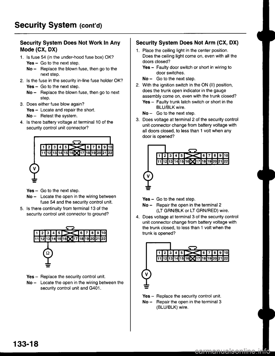
Security System (cont'd)
Security System Does Not Work ln Any
Mode (CX, DX)
1. ls luse 54 (in the under-hood fuse box) OK?
Yes - Go to the next step.
No - Repiace the blown fuse, then go to the
next step.
2. ls the fuse in the securiiy in-line fuse holder OK?
Yes - Go to the next step.
No - Replace the blown fuse, then go to next
srep.
3. Does either fuse blow again?
Yes - Locate and repair the short.
No - Retest the system.
4. ls there battery voltage at terminal 10 of the
security control unit connector?
Yes - Go to the next step.
No - Locate the open in the wiring between
fuse 54 and the security control unit.
ls there continuity from terminal 13 ol the
security control unit connector to ground?
Yes - Replace the security control unit.
No - Locate the open in the wiring between the
securitv control unit and G401.
5.
133-18
Security System Does Not Arm (CX, DX)
1. Place the ceiling light in the center position.
Does the ceiling light come on, even with all the
doors closed?
Yes - Faulty door switch or short in wiring to
door switches.
No - Go to the next steo.
2. With the ignition switch in the ON (ll) position,
does the trunk open indicator in the gauge
assembly come on, even with the trunk closed?
Yes - Faulty trunk latch switch or short in the
BLU/BLK wire.
No - Go to the next step.
3. Does voltage at terminal 2 of the security control
unit connector change from battery voltage with
all doors closed, to less than 1 volt when any
door is ooened?
Yes - Go to the next step.
No - Repair the open in the terminal 2
(LT GRN/BLK or LT GRN/RED) wire.
Does voltage at terminal 3 of the security control
unit connector change from battery voltage with
the trunk closed, to less than 1 volt when the
trunk is oDened?
v]" - R"pt"." tne security control unit.
No - Bepair the open in the terminal 3
(BLU/BLK) wire.
Page 2061 of 2189
Security System Does Not Arm
(HX, LX, EX, DX-V, Si)
1. With all the doors closed, do the doors lock
when you press the transmitter LOCK button?
Yes - Go to the next steo.
No - Go to Doors Do Not Lock With The
Transmitter, on page 130-11 ('96-98
models) or 1 30-18 ('99 models).
Check the trunk open indicator in the gauge
assembly. With the ignition switch in the ON (ll)
position, does the trunk open indicator come on
even with the trunk closed?
Yes - Faulty trunk latch switch or shod in
BLU/BLK wire.
No - Go to the next steo.
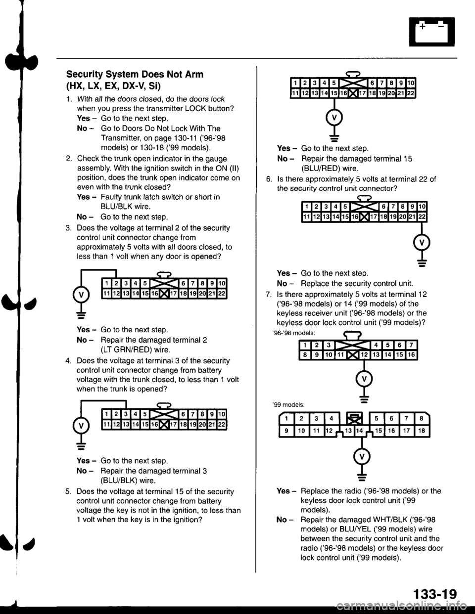
Does the voltage at terminal 2 of the security
control unit connector change from
approximately 5 volts with all doors closed, to
less than 1 volt when any door is opened?
Yes - Go to the next step.
No - Repair the damaged terminal 2
(LT GRN/RED) wire.
Does the voltage at terminal 3 of the security
control unit connector change from battery
voltage with the trunk closed, to less than 1 volt
when the trunk is ooened?
Yes - Go to the next steo.
No - Repair the damaged terminal 3
{BLU/BLK) wire.
Does the voltage at terminal 15 of the security
control unit connector change from battery
voltage the key is not in the ignition, to less than
1 volt when the key is in the ignition?
5.
o.
Yes - Go to the-next step.
No - Repair the damaged terminal 15
(BLU/RED) wire.
ls ihere approximately 5 volts at terminal 22 of
the security control unit connector?
Yes - Go to the next step.
No - Replace the security control unit.
7. ls there approximately 5 volts at terminal 12
('96-'98 models) or 14 ('99 models) of the
keyless receiver unit ('96-�98 models) or the
keyless door lock control unit ('99 models)?'96198 modelsi
Yes - Replace the radio ('96-'98 models) or the
keyless door lock control unit ('99
models).
No - Repair the damaged WHT/BLK ('96-'98
models) or BLU/YEL ('99 models) wire
between the security control unit and the
radio ('96-�98 models) or the keyless door
lock control unit ('99 models).
133-19
Page 2065 of 2189
Security System Alarm Does Not Trigger
When The System ls Armed And The
Trunk Or A Door ls Opened
Security System Does Not "Be€p" 3 Times
When The System is Armed With The Trunk
Or A Door Open (HX, LX, EX, Dx-V SD
1. Place the ceiling light in the center position, then
open and close the doors one at a time. Do all
the doors operate the ceiling light properly?
Yes - Go to the next steo.
No - Repair the ceiling light circuit.
With the ignition switch in the ON (ll) position,
does the trunk open indicator in the gauge
assembly come on with the trunk open?
Yes - Go to the next step.
No - Faulty trunk latch switch or an open in the
BLU/BLK wire.
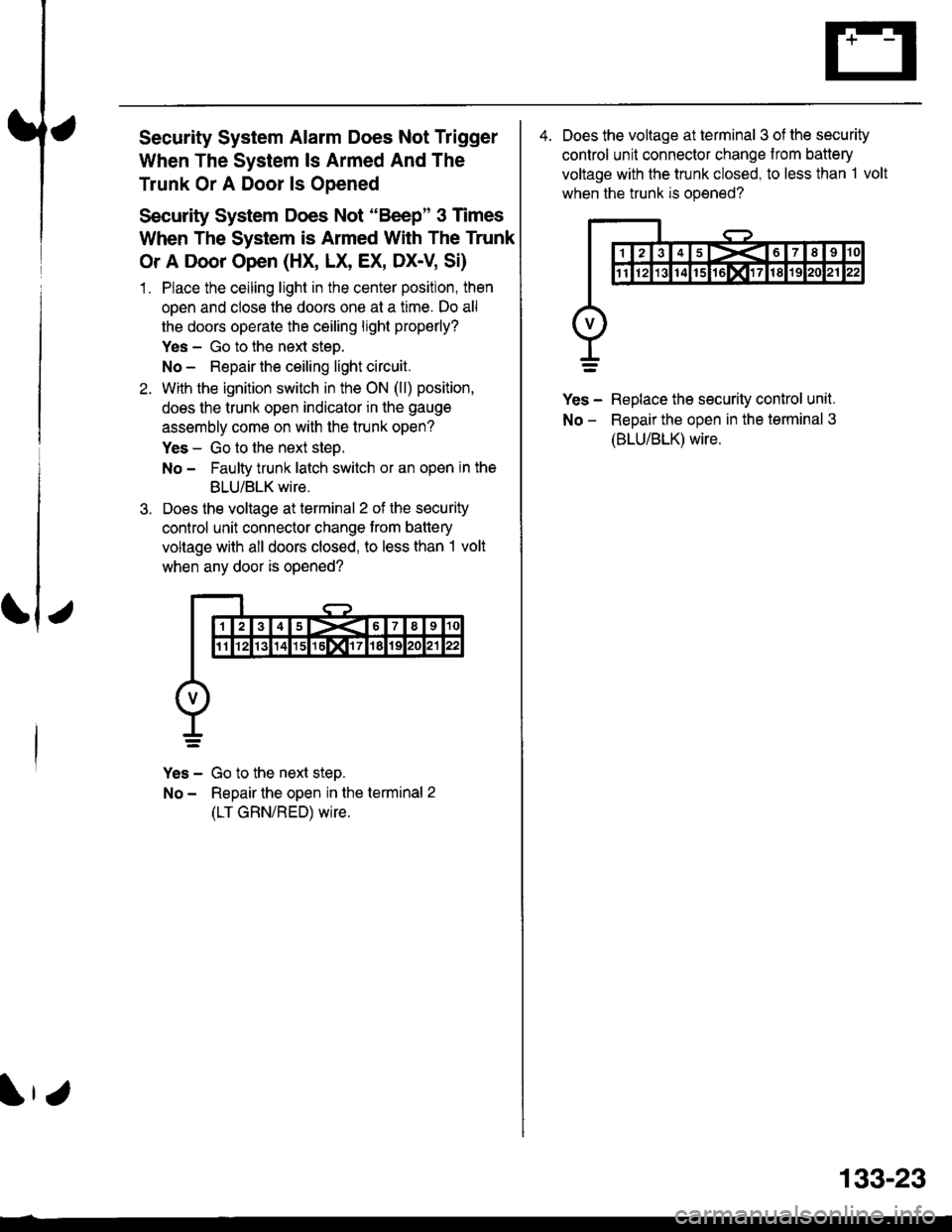
Does the voltage at terminal 2 of the security
control unit connector change trom battery
voltage with all doors closed, to less than I volt
when any door is opened?
Yes - Go to the next step.
No - Repair the open in the terminal 2
(LT GRN/RED) wire.
4. Does the voltage at terminal 3 of the security
control unit connector change from battery
voltage with the trunk closed, to less than 1 volt
when the trunk is opened?
Yes - Replace the security control unit.
No - ReDair the oDen in the terminal 3
(BLU/BLK) wire.
133-23
Page 2108 of 2189
-
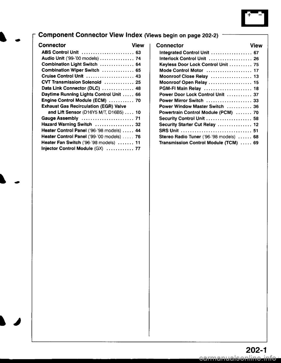
Component Connector View Index (Views begin on page 202-21
Connector View
ABS Control Unit........ ......63
Audio Unit ('99-'00 models) ......74
Combination Light Switch . . . . . . . . . . . . . . . 64
Combination Wiper Switch . . . . . . . . . . . . . . 65
Cruise Control Unit.... .....43
C\TTTransmission Solenoid ............. 25
Data Link Connector (DLC) ..... 48
Daytime Runnlng Lights Control Unit ..... 66
Engine control Module (ECM) ...........70
Exhaust Gas Recirculation (EGR) Valve
and Lift Sensor (D16Y5 Mfl, D1685) . . . . 10
Gauge Assembly .............71
HazardWarnlngSwitch,,. .,,,...,,,,... 32
Heater Control Panel ('96-'98 models) .....44
Heater Control Panel ('99-'00 models) ...., 76
Heater Fan Switch ('96-'98 models) ,,,.... 11
fniector Control Module (GX) ............77
I/
202-1
Connector View
Integrated Control Unit .......,. 67
f nterfock Control Unit .... ...... 26
Keyfess Door Lock Control Unit . . . . , . . . . . 75
Mode Control Motor ... ........'17
Moonroof Close Relay .. .......13
Moonroof Open Relay ... .......15
PGM-FI Main Relay .. .......... 18
Power Door Lock Conlrol Unil ..... ...... 37
Power Mirror Switch .,... ...... 33
Power Window Master Switch .,.........36
Powertrain Control Module (PCM) .......70
Security Control Unit ..., ..,,... 58
Security Starter Cut Belay ... ...,,,....,, 12
SRS Unit ............. 51
Stereo Radio Tuner ('96-'98 models) ...... 68
Transmission Control Module CICM) .....69
Page 2121 of 2189
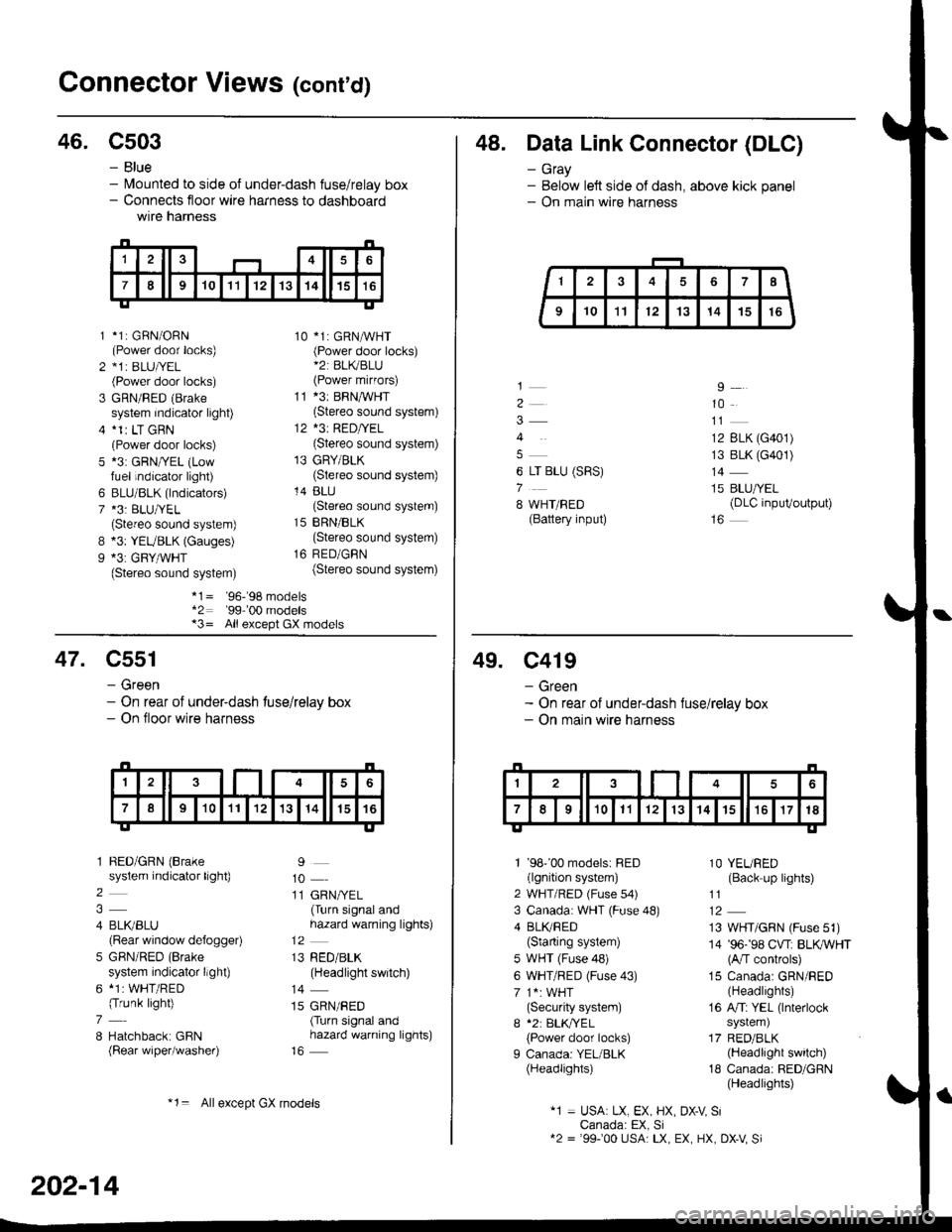
Gonnector Views (conrd)
46. C503
B
9
*1: GBN/ORN(Power door locks)*1r BLU|/EL(Power door locks)
GRN/RED (Brake
system indicator light)*1r LT GRN(Power door locks)*3: GRN/YEL (Lowfuel indicator light)
BLU/BLK (lndicators)*3: BLU/YEL(Stereo sound system)*3: YEUBLK (Gauges)*3: GRY/WHT(Stereo sound system)
10 *1: GRNAVHT(Power door locks)*2: BL(BLU(Power mirfors)
11 *3: BRNMHT(Stereo sound system)
12 *3: RED/YEL(Stereo sound system)
13 GRY/BLK(Stereo sound system)
14 BLU(Stereo sound system)
15 BRN/BLK(Stereo sound system)
16 RED/GBN(Stereo sound system)
- Blue- lvlounted to side of under-dash fuse/relay box- Connects floor wire harness to dashboardwtre narness
1
2
3
5
6
7
*1= '96-'98 models*2: '99-'00 models*3= All except GX models
48. Data Link Connector (DLC)
- Gray- Below left side of dash, above kick panel- On main wire harness
4
6 LT BLU (SRS)
7
8 WHT/BED(Battery input)
9
10
12 BLK (G401)
13 BLK (G401)
14
15 BLU/YEL(DLC inpuVoutput)
47. C551
- Green- On rear of under-dash tuse/relay box- On floor wire harness
1 BED/GRN (Brake
system indicator light)
2
4 BLI(BLU(Rear window defogger)
5 GBN/RED (Brake
system indicator llght)
6 *1: WHT/RED(Trunk light)
7
8 Hatchback: GBN(Rear wiper/washer)
9
10
11 GRN/YEL(Turn signal andhazard warning lights)
13 RED/BLK(Headlight switch)
14
15 GRN/RED(Turn signal andhazard warning lights)
202-14
*1= Allexcept GX models
49. C419
- Green- On rear of under-dash fuse/relay box- On main wire harness
1 '98''00 models: RED(lgnition system)
2 WHT/RED (Fuse s4)
3 Canada: WHT (Fuse 48)
4 BLI(RED(Starting system)
5 WHT (Fuse 48)
6 WHT/RED (Fuse 43)
7 1*: WHT(Security system)
I *2: BLK,TYEL
{Power door locks)
I Canada: YEL/BLK(Headlights)
1O YEURED(Back up lights)
11
13 WHT/GRN (Fuse 51)
14 '96-'98 CVT: BLKWHT(A/T controls)
15 Canada: GRN/RED(Headlights)
16 A/Ti YEL (lnterlock
system)
17 RED/BLK(Headlight switch)
18 Canada: RED/GRN(Headlights)
"1 = USA: LX, EX, HX, DX-V SiCanada: EX, Si12 = '99100 USA: LX, EX, HX, DX-V Si
Page 2123 of 2189
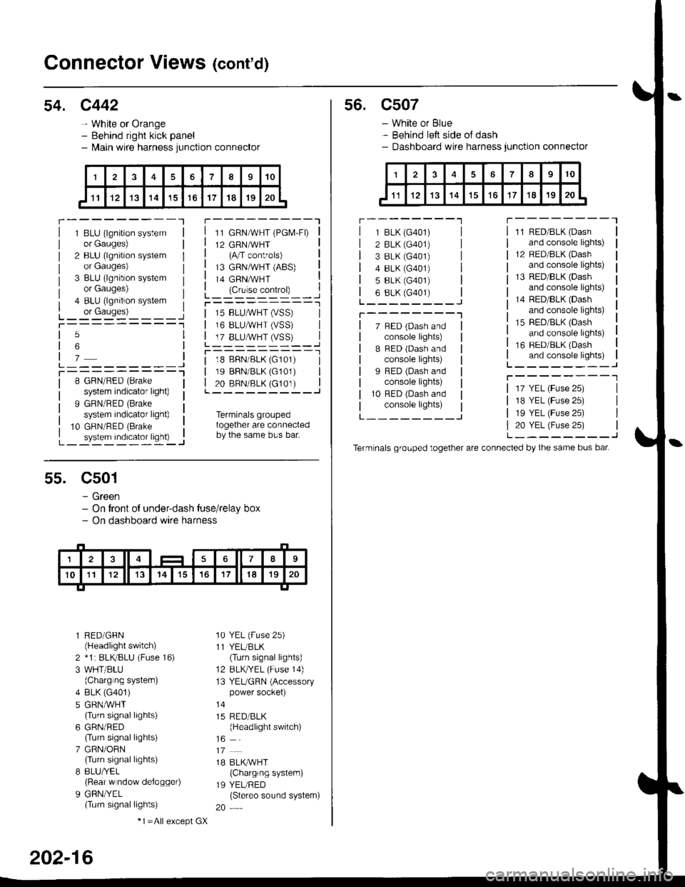
Connector Views (cont'd)
54. c442
- White or Orange- Behind right kick panel- l\,lain wire harness junction connector
r---------Tr---------"1
1 BLU (lgnition systemor Gauges)
2 BLU (lgnition syslemor Gauges)
3 BLU (lgnition systemor Gauges)
4 BLU (lgnition system
L_ or causes)L_-:-:::'-'�____Jt-----------1
11 GRN/WHT (PGM-FD
12 GRN/WHT(A/T controls)
13 GRNMHT (ABS)
14 GRNMHT
L_ lc,r'." .oIr"D_ _ _.jr----------_l
5
6
7L---------JT----------l8 GRN/RED (Brake
system indicator light)
9 GRN/RED (Brake
system indicator light)
10 GRN/RED (Brake
_ system indicator ligh0 -..1
| 15 BLUMHT (vSS) |I 16 BLUMHT (VSS) I
L T?_BLUSTrySS)--..]
l--------- - -l
| 18 BFN/BLK (G101) I| 19 BBN/BLK (G101) || 20 BRN/BLK (c101) |L---------J
Terminals groupedtogether are connectedby the same bus bar.
55. C501
- Green- On tront of under-dash tuse/relay box- On dashboard wire harness
l RED/GFN(Headlight switch)
2 *1 : BLKBLU (Fuse 16)
3 WHT/BLU(Charging systern)
4 BLK (G401)
5 GRNMHT(Turn signal lights)
6 GRN/RED(Turn signal lights)
7 GRN/ORN(Turn signal lights)
8 8LU/YEL(Rear w ndow delogger)
9 GFN/YEL(Turn signal lights)
'10 YEL (Fuse 25)
11 YEL/BLK(Turn signal lights)
12 BLKTYEL (Fuse 14)
13 YEUGRN (Accessorypower socket)
15 RED/BLK(Headlight switch)
1B BLK/WHT(Charglng system)
19 YEL/RED(Stereo sound system)
20
202-16
-1 =All e),cept GX
s6. c507
- White or Blue- Behind left side oJ dash- Dashboard wire harness junction connector
r --------'lT---------l
7 BED (Dash andconsole lights)
B BED (Dash andconsole lights)
I RED (Dash andconsole lights)
10 RFD (Dash andconsole lights)
11 RED/BLK (Dash
and console lights)
12 RED/8LK (Dash
and console lights)
13 RED/BLK {Dashand console lights)
14 RED/BLK (Dash
and console lights)
15 RED/BLK (Dash
and console lights)
16 RED/BLK (Dash
and console lights)L--------J
T--------T
L---_---_J
1 BLK (G401)
2 BLK (G401)
3 8LK {G401)4 8LK (G401)
5 BLK (G401)
6 8LK (G401)L________J
T--------"1
17 YEL (Fuse 25)
18 YEL (Fuse 25)
19 YEL (Fuse 25)
20 YEL (Fuse 25)L--------J
Term nals grouped together are connected by the same bus bat