Page 1178 of 2189
Rear Brake Pads
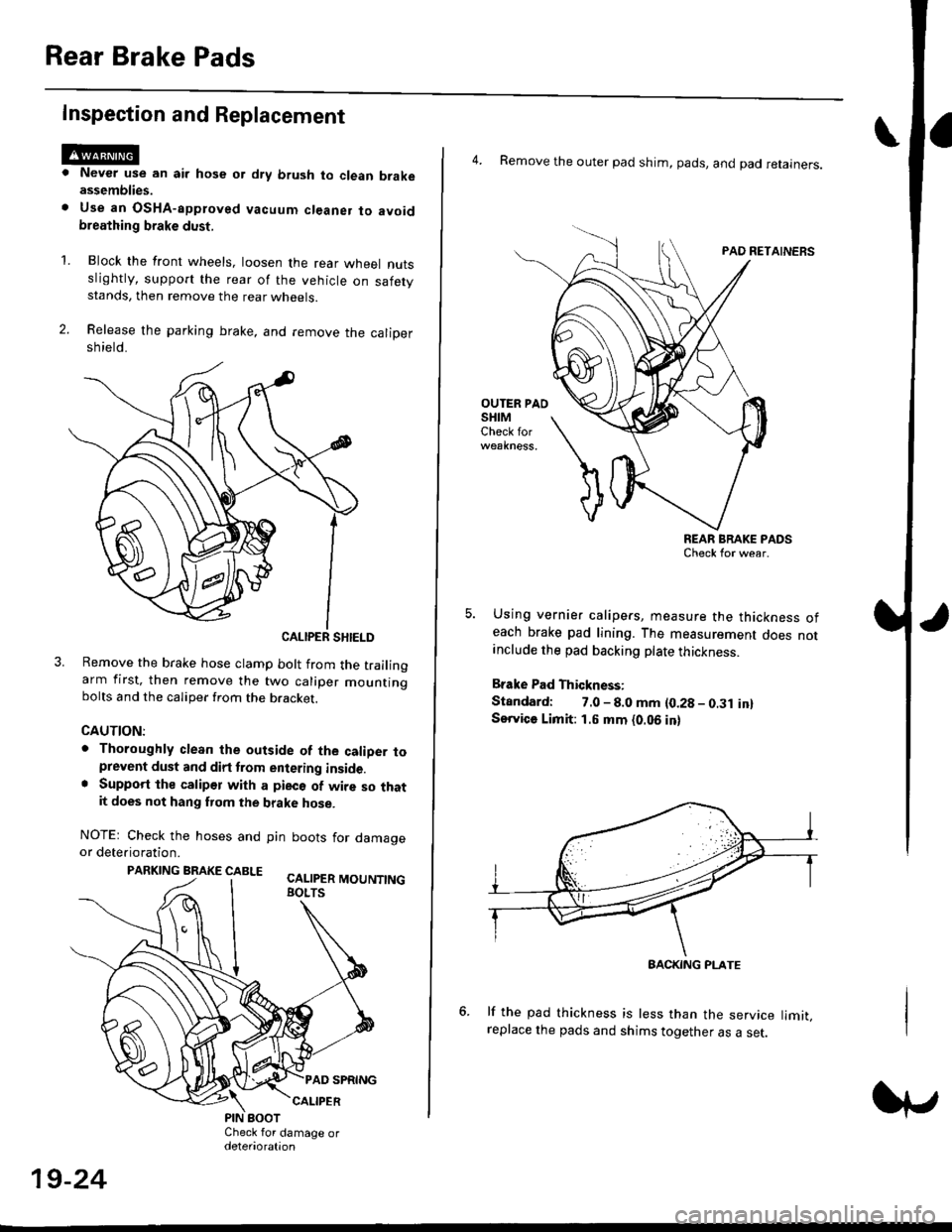
Inspection and Replacement
Never use an air hose or dry brush to clean brakeassemblies.
Use an OsHA-apptoved vacuum cl€aner to avoidbreathing brake dust,
Block the front wheels, loosen the rear wneet nutsslightly, support the rear of the vehicle on safetystands, then remove the rear wheels.
Release the parking brake, and remove the calioersh ield.
CALIPER SHIELD
Remove the brake hose clamp bolt from the trailingarm first, then remove the two caliper mountingbolts and the caliper from the bracket.
CAUTION:
. Thoroughly clean the outside of the caliDer toprevent dust and dirt trom entering inside.. Support the calipor with a pieco of wire so thatit does not hang fuom the brake hose.
NOTEr Check the hoses and pin boots for damageor deterioration.
PARKING BRAKE CABLE ^.. ._-_ ---.
'L
19-24
4. Remove the outer pad shim, pads, and pad retainers.
PAO RETAINERS
OUTER PAOSHIMCheck for
REAR BRAKE PADSCheck for wear.
Using vernier calipers, measure the thickness ofeach brake pad lining. The measurement does notanclude the pad backing plate thickness.
Brake Pad Thickness:
Standard: 7.0 - 8.0 mm {0.28 - 0.31 in}Service Limit: 1.5 mm {0.06 in}
lf the pad thickness is less than the service limit,replace the pads and shims together as a set.
BACKING PI-ATE
Page 1181 of 2189
Rear Brake Caliper
Disassembly
@f l',lever use an air hose or dry brush to clean
assemblies.
. Use an OsHA-approved vacuum cleaner to
brake
avoid
breathing brake dust.
. Contaminated brake discs or pads reduce stopping
ability.
CAUTION:
. Do not spill brake tluid on the cal; h may damage the
paint; if brake fluid does contact the paint, wash ii
ofl immediatelY with water.
. To prevent spills, cover the hose ioints whh rags or
shop tow€ls.
. Clean all parts in brake fluid and air dry; blow out all
passagss with complessed air.
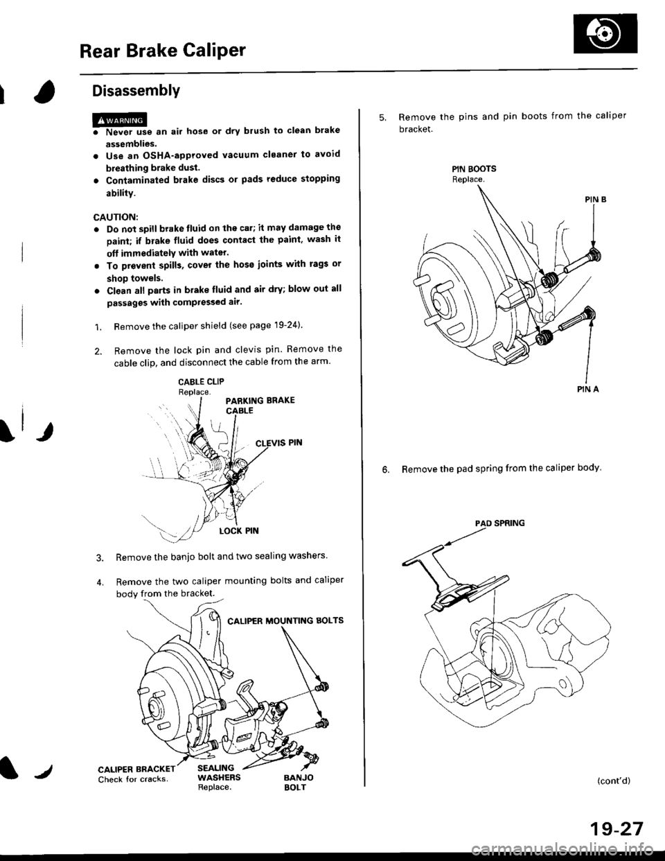
1. Remove the caliper shield (see page 19-24).
2. Remove the lock pin and clevis pin. Remove the
cable clip, and disconnect the cable from the arm
CABLE CLIP
Remove the banjo bolt and two sealing washers
Remove the two caliper mounting bolts and caliper
body from the bracket.
CALIPER MOUNTNG AOLTS
CALIPER BRACKETCheck for cracksSEALINGWASHERSReplace.BANJOBOLT
5, Remove the pins and pin boots from the caliper
bracket.
6. Remove the pad spring from the caliper body
PIN A
(cont'd)
19-27
Page 1188 of 2189
Rear Brake Caliper
Reassembly (cont'dl
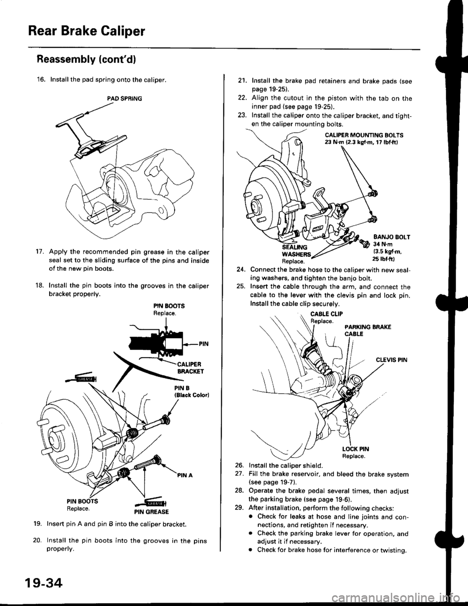
'16. Installthe pad spring onto the caliper.
Apply the recommended pin groase in the caliper
seal set to the sliding surface of the pins and inside
of the new pin boots.
Install the pin boots into the grooves in the caliper
bracket properly.
PIN BOOTSReplsce.
(Bl.ck Colorl
PINRepl6ce.
19. Insert pin A and pin B into the caliper bracket.
20. Install the pin boots into the grooves in thepropefly.
PAD SPRING
11.
PIN GREASE
19-34
pr ns
22.
21. Install the brake pad retainers and brake pads (see
page 19-25).
Align the cutout in the piston with the tab on the
inner pad (see page 19-25).
Install the caliper onto the caliper bracket. and tight-
en the caliper mounting bolts.
CALIPER MOUNTING BOLTS23 N.m {2.3 kg{.m. 17 lbf.ft)
WASHERSReplace.
BANJO BOLT34 N.m13.5 kg{.m.25 rbtft)
24.Connect the brake hose to the caliper with new seal,
ing washers, and tighten the banjo bolt,
Insert ths cable through the arm, and connect the
cabls to the lever with the clevis pin and lock pin.
Install the cable clip securely.
CLEVIS PIN
-t
//t
LOCK PINRoplace.
26. Install the caliDer shield.
27. Fill the brake reservoir, and bleed the brake svstem(see page 19-71.
28. Operate the brake pedal several times, then adjust
the parking brake (see page 19-6).
29. After installation, perform the following checks:. Check for leaks at hose and line joints and con-nections, and retighten if necessary.. Check the parking brake lever for operation, and
adjust it if necessary.
. Check for brake hose for interference or twistinq.
Page 1191 of 2189
t-
Brake Shoe Disassembly
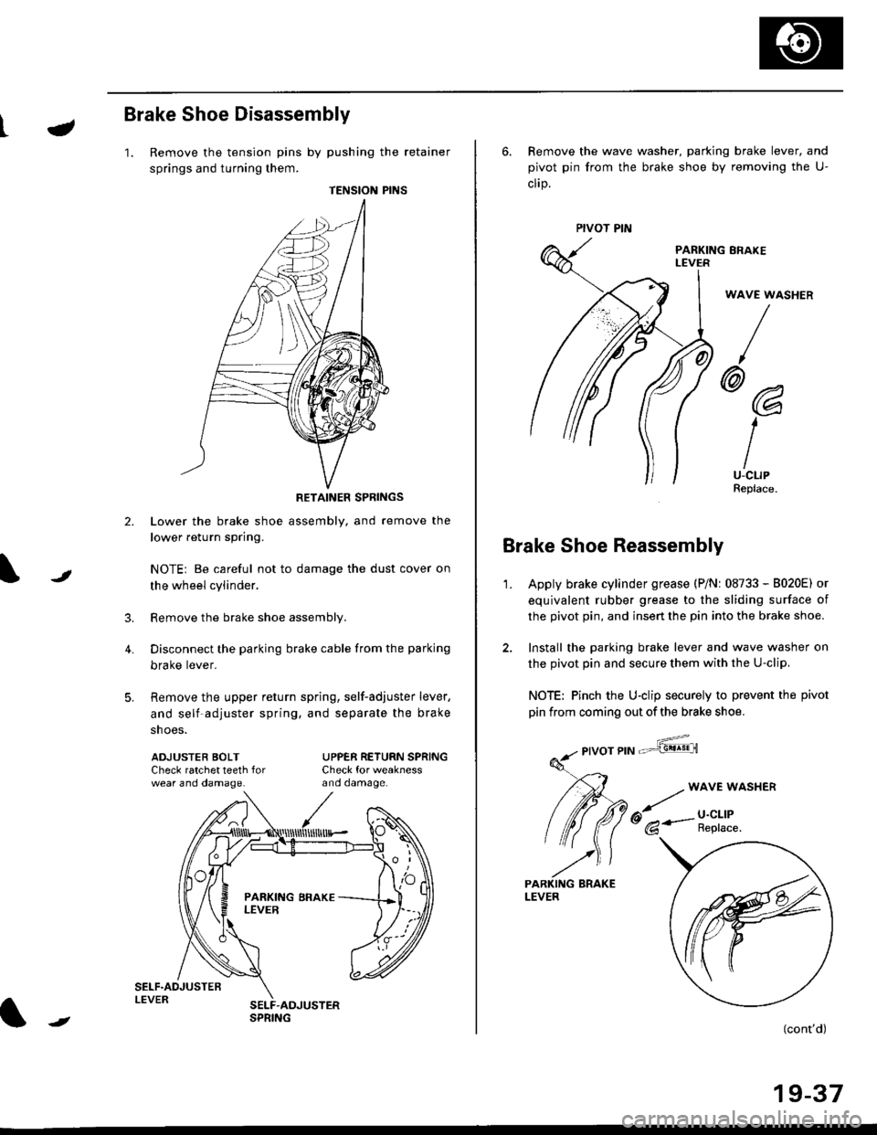
1. Remove the tension pins by pushing the retainer
springs and turning them.
TENSION PINS
RETAINER SPRINGS
Lower the brake shoe assembly, and remove the
lower return spring.
NOTEi Be careful not to damage the dust cover on
the wheel cylinder.
Remove the brake shoe assembly.
Disconnect the parking brake cable from the parking
brake lever.
Remove the upper return spring, self-adjuster lever,
and self-adjuster spring, and separate the brake
snoe5.
t
3.
4.
ADJUSTEB BOLTCheck ratchet teeth forwear ano oamage.
UPPER RETURN SPRINGCheck for weaknessano oamage.
ll
,'/
N
r
//
t
6. Remove the wave washer, parking brake lever, and
pivot pin from the brake shoe by removing the U-
clrp.
PARKING ERAKEI-EVER
WAVE WASHER
/
@@
I
IU-CLIPReplace.
Brake Shoe Reassembly
1.Apply brake cylinder grease (P/Nr 08733 - B020E) or
equivalent rubber grease to the sliding surface of
the pivot pin, and insert the pin into the brake shoe.
Install the parking brake lever and wave washer on
the pivot pin and secure them with the U-clip,
NOTE: Pinch the U-clip securely to prevent the pivot
pin from coming out of the brake shoe.
,6;::"'
(cont'd)
19-37
LEVER
Page 1192 of 2189
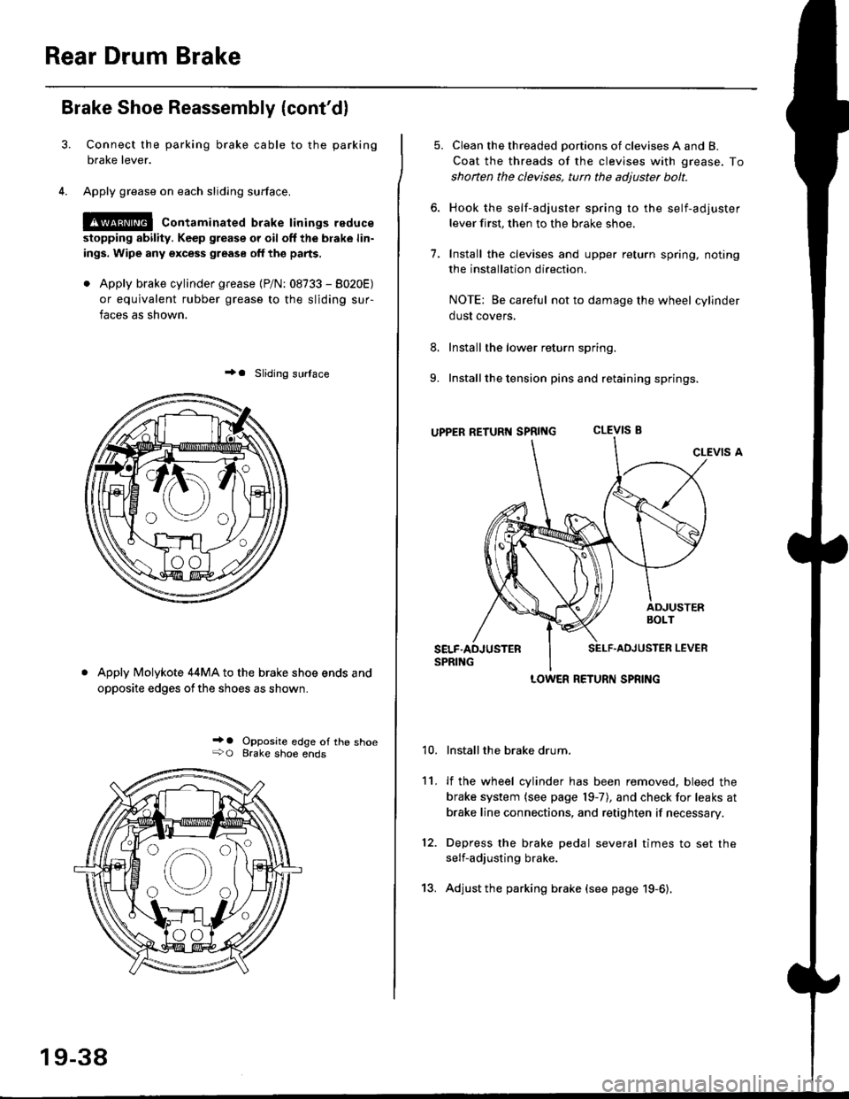
Rear Drum Brake
Brake Shoe Reassembly {cont'dl
Connect the parking brake cable to the parking
brake lever.
Apply grease on each sliding surface.
!@ contaminated brake linings reduce
stopping ability. Keep grease or oil off the blake lin-
ings. Wipe any excess grease off the parts,
. Apply brake cylinder grease {P/N: 08733 - 8020E)
or equivalent rubber grease to the sliding sur-
faces as shown.
+a Sliding surlace
Apply Molykote 44MA to the brake shoe ends and
opposite edges ofthe shoes as shown.
_' o Opposite edge of the shoe+O Brake shoe ends
19-38
13.
5. Clean the threaded portions of clevises A and B.
Coat the threads of the clevises with grease. To
shoften the clevises, tun the adjuster bolt.
6. Hook the self-adjuster spring to the self-adjuster
lever first, then to the brake shoe
7. Install the clevises and upper return spring. noting
the installation direction.
NOTE: Be careful not to damage the wheel cylinder
dust covers,
8. Install the lower return spring.
9. Install the tension pins and retaining springs.
uppER RETURT{ SpRtNG CLEVIS B
CLEVIS A
Installthe brake drum.
lf the wheel cylinder has been removed, bleed the
brake system (see page 19-7), and check for leaks at
brake line connections, and retighten if necessary.
Depress the brake pedal several times to set the
self-adjusting brake.
Adjust the parking brake (see page 19-6).
't0.
11.
12.
LOWER RETURN SPRING
Page 1195 of 2189
Parking Brake Cable
LInspection and Replacement
CAUTION: The parking blake cables must not be bent or distorted. This will lead to stiff operation and premature cable
failure.
PARKING BRAKE CABLECheck for faulty movement.
PARKING BRAKE LEVERCheck for smoothoperation.
\i ,
EOUALIZER
PARKING BRAKE SWITCH
Disc Brake Type:
Disconnect the parking brake cable from the lever on the
caliper by removing the lock pin and clevis pin, and remove
the cable from the arm by removing the clip
CLEVIS PIN
Drum Brake Type:
Remove the parking brake cable from the backing plate
using a 12 mm offset wrench as shown.
12 mmOFFSET WRENCH(Commercially available)
DISC BRAKE TYPE:
CLEVIS PIN
PARKING ERAKE CABLE
{tt
BACKING PLATE
/
19-41
Page 1231 of 2189
l}
e\
Body ('96 modell
Doors
Front Door Index (4D) ...20-2
Rear Door Index {4Dl .....20-8
Door fndex lzDl3Dl .......20-14
Emblems
f nstallation 20-118
Exterior
Component Location Index ............... 20-93
*Frame Repair Chart .......... 20-120
* Interior
Component Location Index ............... 20-58
Mirrors
Mirror Rep|acement .................. ......... 20-24
Mirror Holder/Gover Replacement ... 20-25
Rearview Mirror Reolacement .......... 20-25
Moonroof
lndex .......... .....................20-50
Opener Cable/Opener and Latch/
Wiper and Washer
Component Location Index .......... ...,. 20-107
Seats and Seat Belts
Gomponent Location Index .......... ..... 20-73
Sub-frame ....20-119
Windshield, Rear Window and Ouarter Glass
Index .......... .....................20-26
Body {'97 modell
Body ('98 modell
Body ('99 modell
Body ('00 model)
20-123
20-131
20-135
20-141
It
Page 1234 of 2189
Doors
Door Panel Replacement
NOTE; Take care not to scratch the door panel and otherpans.
1. Remove:
. Inner handle (see page 20-3)
. Mirror mount cover panel (see page 20-24)
2. lf applicable, remove the regulator handle by pulling
HANOLE
3. Remove the door grip cover and speaker cover, thenremove the screws.
>: Screw locations, 5POWER WTNOOWswtTct{
the clip out with a wire hook.
20-4
4. Release the clips that hold the door panel. Remove
the door panel by pulling it upward.
NOTE: Remove the door panel with as little bending
as possible to avoid creasing or breaking it.
95 mm {3.74 in.)
.L12 mm(0.47 in.) fTRIM PADREMOVER(Commercially
availablelSnap-on#A'177, o.equivalenllmm(0.04 in.l
r_
rr-l
45 mm(1.77 in.l
>i Clip loc.tions, 5
lu-i
J$- I
:fe i
cL,P / IREMovERil I
_ _t/
Dasconnect the;peaker connector,
5. lnstallation is the reverse of the removal procedure.