1996 HONDA CIVIC Cable
[x] Cancel search: CablePage 1031 of 2189
t
Adjustment
!@ Make sure lifts, jacks and safety stands are
placed properly (see section 1).
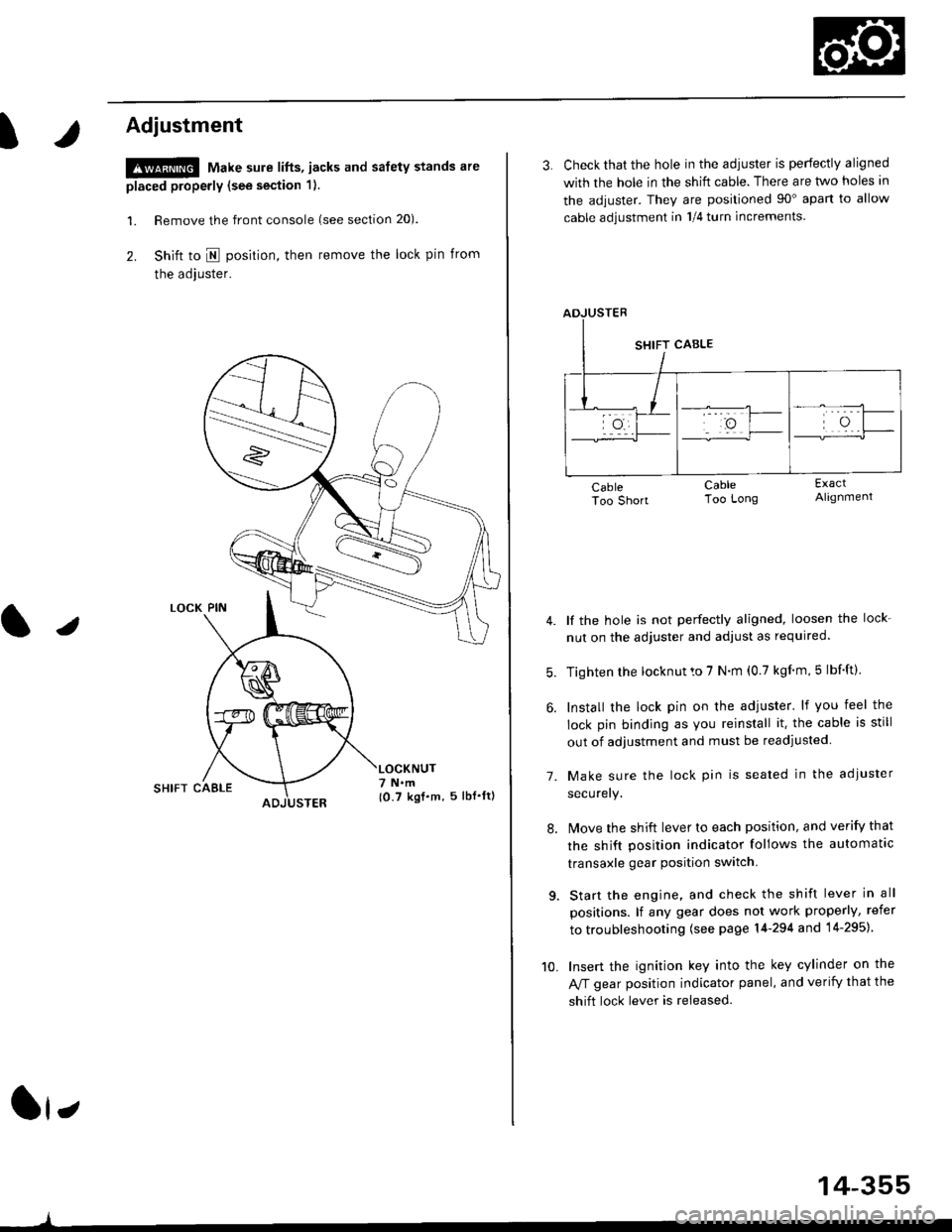
l. Remove the front console (see section 20).
2. Shift to I posirion, then remove the lock pin from
the adjuster.
SHIFT CAELE
l,
,l
{0.7 kgf.m, 5lbf'ltl
3. Check that the hole in the adiuster is perfectly aligned
with the hole in the shift cable. There are two holes in
the adjuster. They are positioned 90" apart to allow
cable adjustment in 1/4 turn increments.
lf the hole is not perfectly aligned, loosen the lock-
nut on the adjuster and adjust as required.
Tighten rhe locknut to 7 N.m (0.7 kgim,5 lbf'ft).
Install the lock pin on the adjuster' lf you feel the
lock pin binding as you reinstall it. the cable is still
out of adjustment and must be readjusted
Make sure the lock pin is seated in the adiuster
securery.
lMove the shift lever to each position, and verify that
the shift position indicator follows the automatlc
transaxle gear position switch.
Start the engine, and check the shift lever in all
positions. lf any gear does not work properly, refer
to troubleshooting (see page 14-294 and 14-295).
Insert the ignition key into the key cylinder on the
Aff gear position indicator panel, and verify that the
shift lock lever is released.
7.
10.
14-355
Page 1039 of 2189
Driveshafts
Disassembly (cont'dl
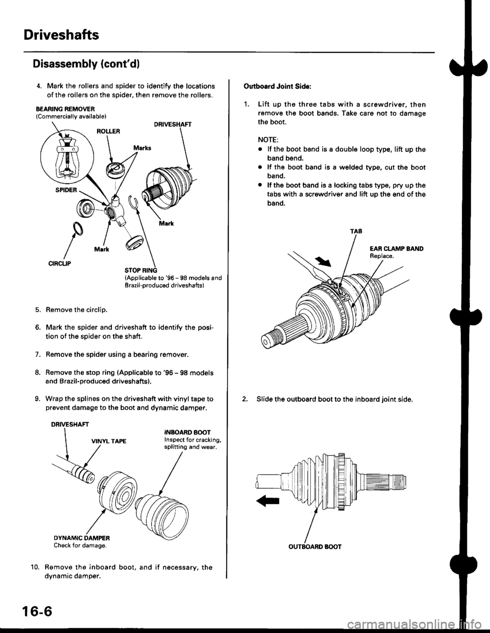
4. Mark the rollers and spider to identify the locations
of the rollers on the sDider, then remove the rollers.
B€ARING REMOVER{Commerciallv available}
STOP RING(Applicable to '96 - 98 modols andErazil-produced driveshafts)
Remove the circlip.
Mark the spider and driveshaft to identify the posi-
tion ot the spider on the shaft.
Remove the spider using a bearing remover.
Remove the stop ring (Applicable to '96 - 98 models
and Brazil-produced driveshafts).
Wrap the splines on the drivsshaft with vinyl tape to
prevent damage to the boot and dynamic damper.
DRIVESHAFT
1.
VINYL TAPE
DYNAMIC DAMPERCheck for damage.
Remove the inboard
dynamic damper.
INBOARO AOOTInspect for cracking,splitting and wear.
16-6
boot, and if necessary, the
Outboard Joint Side:
1. Lift up thc three tabs with a screwdriver, then
remove the boot bands, Take care not to damage
the boot.
NOTE:
. lf the boot band is a double loop type, lift up the
band bend.
. lf the boot band is a welded type, cut the boot
band.
. lfthe boot band is a locking tabs type, pry up the
tabs with a scr€wdriv€r and lift uo the snd of the
band.
2. Slide the outboard boot to the inboard ioint side.
TAB
OUTBOABD BOOT
Page 1059 of 2189
Component Locations
tlndex
Manual Steering
NOTE:
. lf an intact airbag assembly has been removed from a scrapped vehicle or has been found defective or damaged dur-
ing transit. storage or service, it should be deployed (see section 24)'
o Before removing the gearbox, remove the driver's airbag assembly and steering wheel
. After insta lling the gearbox, check the wheel alignmentand adjust if necessary
SRS components are located in this area. Review the SRS component locations, precautions, and procedures in the SRS
section 124) before performing repairs or service'
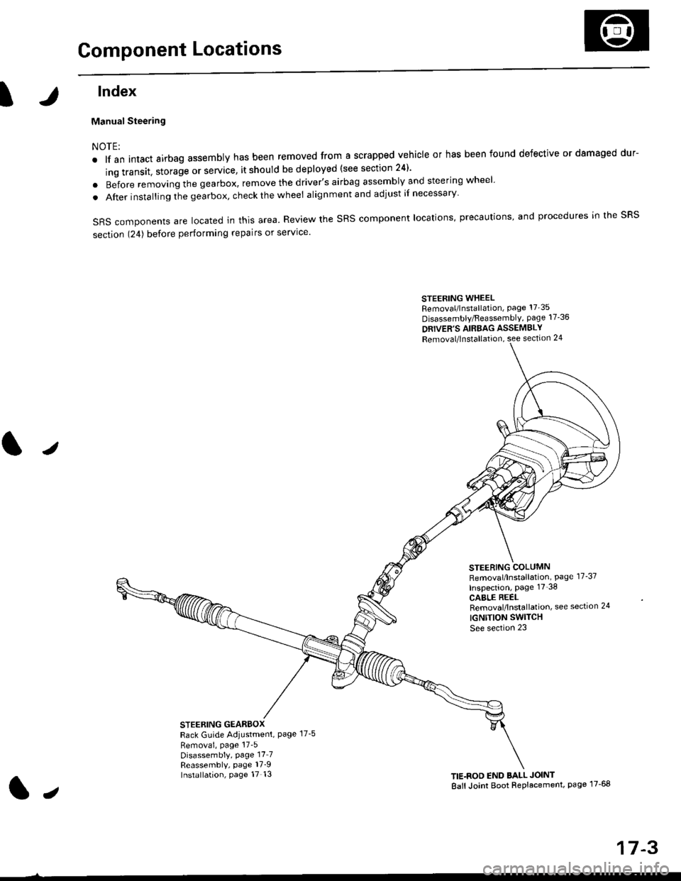
STEERING WHEELRemoval/lnstallation, Page 17'35
Disassembly/FeassemblY, page 17-36
DRIVER'S AIRBAG ASSEMBLY
Removal/lnstallation, see section 24
STEERING COLUMNRemoval/lnstallation, Page 17-37
Inspection, page 17'38
CABLE REELRemoval/lnstallation, see section 24
IGNTTION SWITCH
See section 23
STEERING GEARBOXRack Guide Adiustment, Page 17-5
Removai, page 17'5Disassembly, Page 17_7Reassembly, page 17_9Installation, page 17 13TIE.ROD END BALL JOINT
Ball Joint Boot Replacement, page 17-68
J
t,
17-3
Page 1070 of 2189
Steering Gearbox
Installation (cont'dl
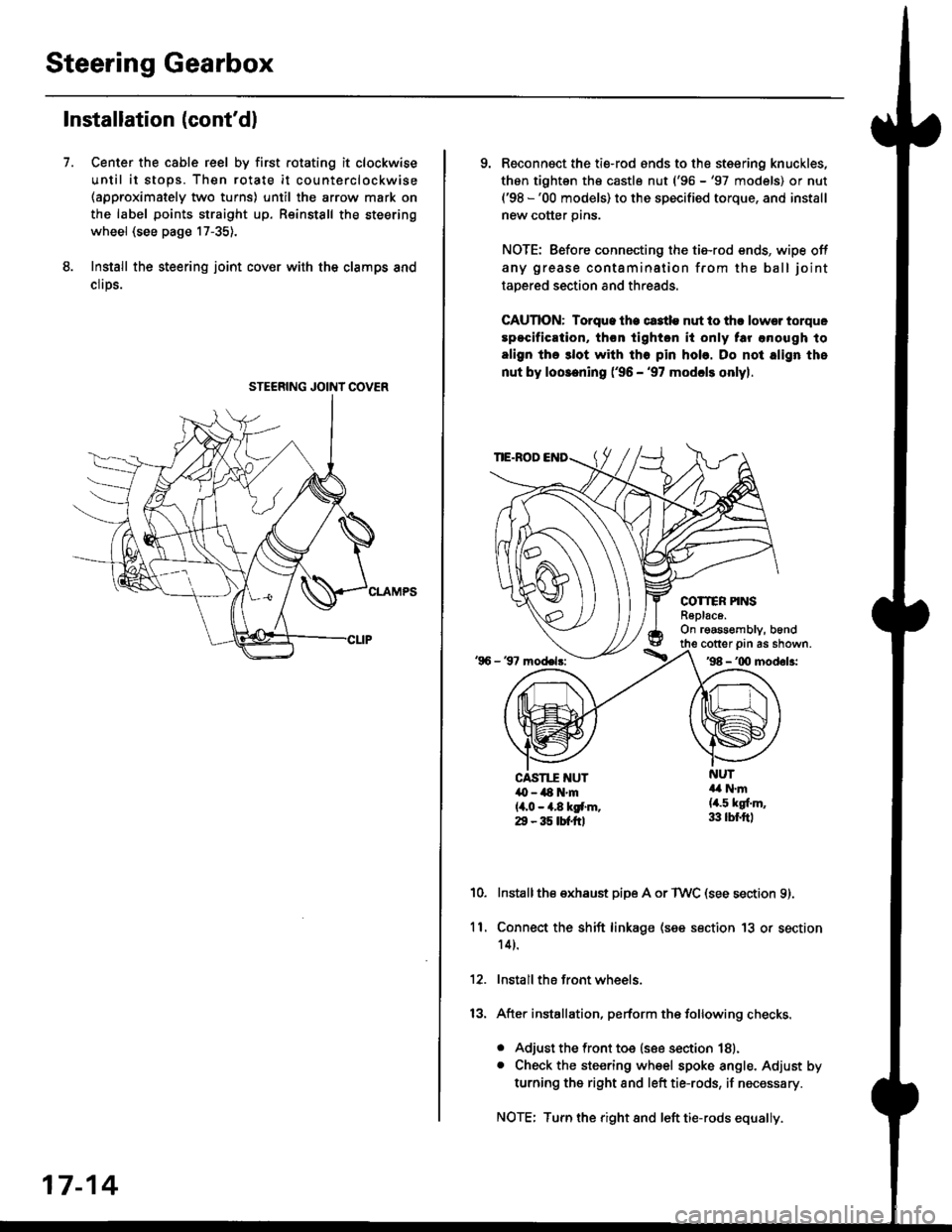
Center the cable reel by first rotating it clockwise
until it stops. Then rotate it counterclockwise(approximately two turns) until the arrow mark on
the label points straight up. Reinstall the steering
wheel (see page 17-35).
Install the steering joint cov€r with the clamps and
clrps.
7.
STEERING JOINI COVER
17-14
9. Reconnsct the ti€-rod ends to the steering knuckles,
thon tightsn th€ castle nut ('96 -'97 models) or nut('98 -'00 models) to the specified torque, and install
new cotter pins.
NOTE: Before connecting the tie-rod ends, wipe off
any grease contamination from the ball joint
tapered section and threads.
CAUTION: Torque lhe ct3tle nut to thr lowsr torque
spocification, th€n tighton it only tar anough to
align the 3lot with tho pin hob. Do not align the
nut by loosening ('96 - '97 modcls onlyl.
TIE.ROD
COTTER PINSR6plac6.On rgassombly, b6nd
'96 - 37 model3:
cotter prn as shown.'98 - '00 modol3:
NUT4a N.m(4.5 kgf.m,33 lbr.ftl
CAST1T NUT,O - ilt N'm{4,0 - 4.8 kgf.m.29 - 35 tbtftl
10.Installthe exhaust pipe A or TWC (see section 9).
Connect the shift linkage (see section 13 or section
14).
Install the front wheels.
After installation, perform the following checks.
. Adjust the front toe (see section 18).. Check the steering wheel spoke angle. Adjust by
turning the right and left tie-rods, if necessary.
NOTE: Turn the right and left tie-rods equally.
ll.
Page 1091 of 2189
Steering Wheel
l,/
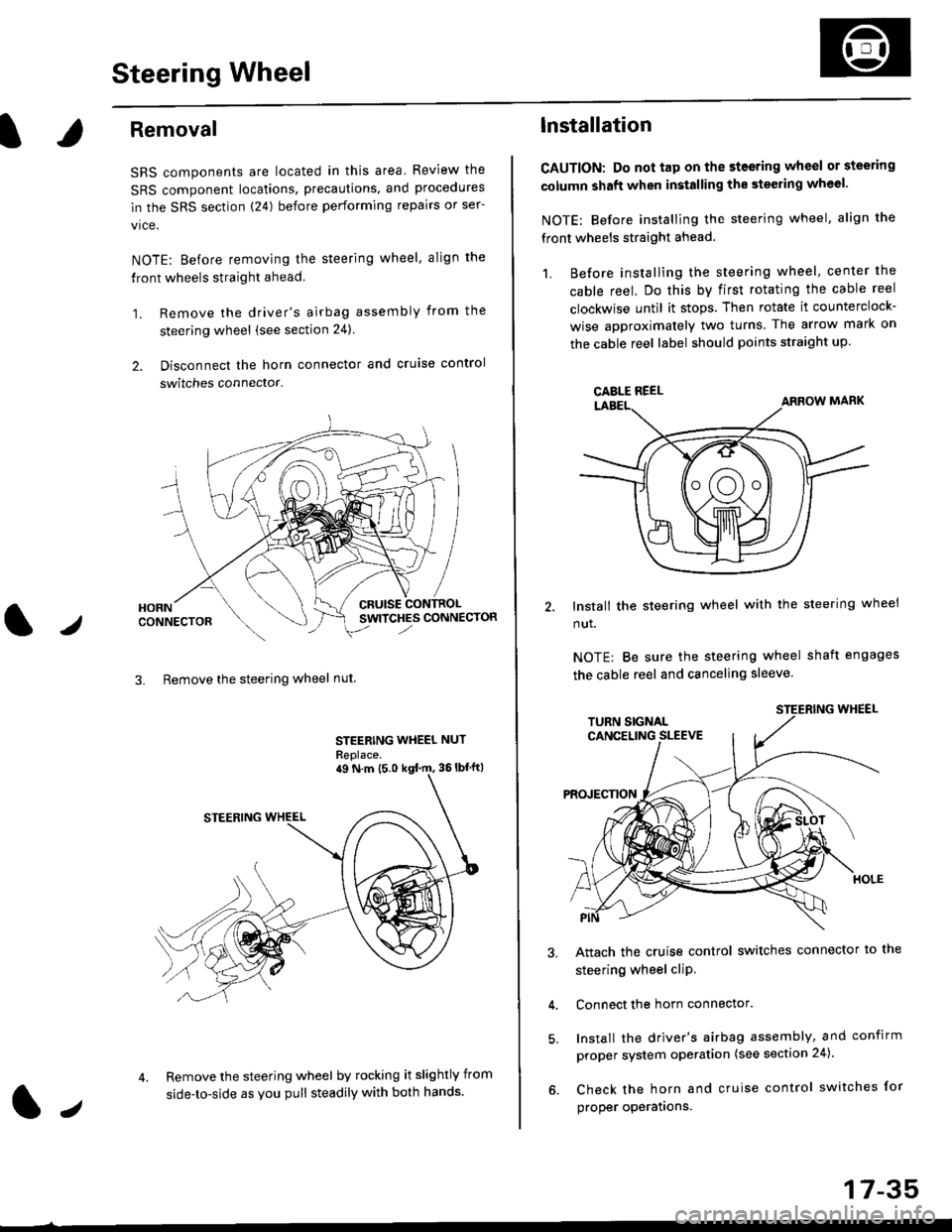
Removal
SRS components are located in this area Review the
SRS component locations, precautions, and procedures
in the SRS section (24) before performing repairs or ser-
vice.
NOTE: Before removing the steering wheel. align the
front wheels straight ahead.
1. Remove the driver's airbag assembly from the
steering wheel (see section 24)
2. Disconnect the horn connector and cruise control
switches connector.
CRUISESWITCHES CONNECTOR
3. Remove the steering wheel nut
STEERING WHEEL NUT
Replace.
Remove the steering wheel by rocking it slightly from
side-to-side as you pull steadily with both hands.
ag N.m {5.0 kgt rn, 36lbfft)
1.,
17-35
lnstallation
CAUTION: Do not tap on the steering wheel or steering
column shaft when installing the stsering wheel.
NOTE: Before installing the steering wheel, align the
front wheels straight ahead.
1. Before installing the steering wheel, center the
cable reel, Do this by first rotating the cable reel
clockwise until it stops. Then rotate it counterclock-
wise approximately two turns The arrow mark on
the cable reel label should points straight up.
Install the steering wheel with the steering wheel
nut.
NOTE: Be sure the steering wheel shaft engages
the cable reel and canceling sleeve.
Attach the cruise control switches connector io the
steering wheel cliP,
Connect the horn connector.
Install the driver's airbag assembly, and confirm
proper system operation (see section 24).
Check the horn and cruise control switches for
proper operatrons.
CAELE REEL
Page 1093 of 2189
Steering Column
I
Removal/lnstallation
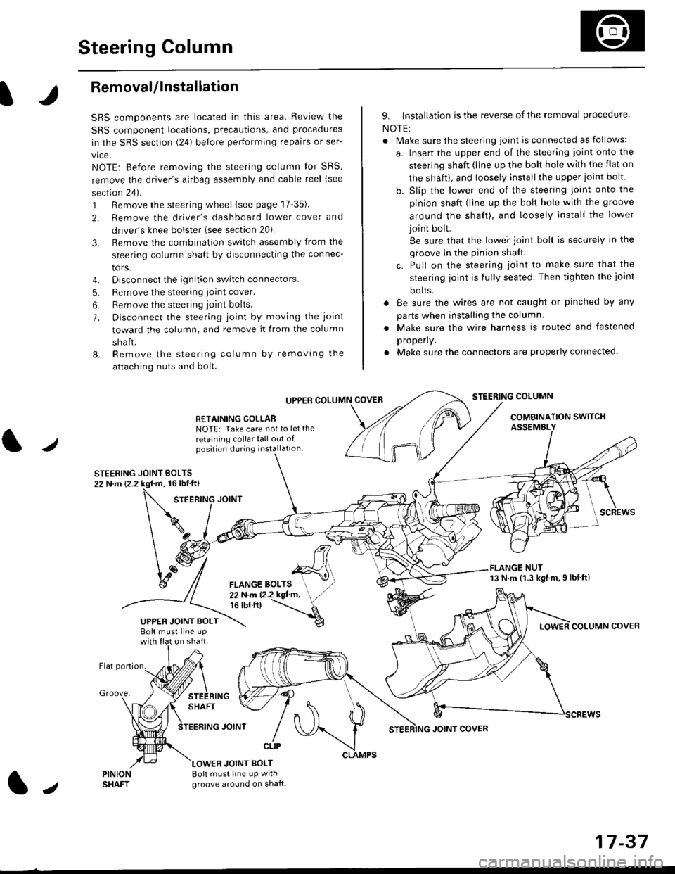
SRS components are located in this area. Review the
SRS component locations, precautions, and proceclures
in the SRS sectron (24) before pertorming repairs or ser-
vice.
NOTE: Before removing the steering column for SRS,
remove the driver's airbag assembly and cable reel lsee
section 24).
1. Remove the steering wheel (see page 17 35).
2. Remove the driver's dashboard lower cover and
driver's knee bolster (see section 20).
3. Remove the combination switch assembly from the
steering column sha{t by disconnecting the connec-
tors.
4. Disconnect the ignition switch connectors.
5. Remove the steering joint cover.
6. Bemove the steering joint bolls.
7. Disconnect the steering ioint by moving the joint
toward the column, and remove it from the column
shaft.
8. Remove the steering column by removing the
attaching nuts and bolt.
UPPER
RETAINING COLLABNOTE: Take care not to let the
retaining collar fall out ofposition during installation.
STEERING JOINT BOLTS22 N.m {2.2 kgf.m, 16lbtft}
9. Installation is the reverse of the removal procedure
NOTE:
. Make sure the steering joint is connected as follows:
a. Insert the upper end of the steering ioint onto the
steering shaft (line up the bolt hole with the flat on
the shait), and loosely install the upper joint bolt.
b. Slip the lower end of the steering joint onto the
pinion shaft (line up the bolt hole with the groove
around the shaft), and loosely install the lower
joint bolt.
Be sure that the lowei joint bolt is securely in the
groove in the pinion shaft.
c. Pull on the steering joint to make sure that the
steering joint js fully seated. Then tighten the ioint
bolts.
. 8e sure the wires are not caught or pinched by any
parts when installing the column
. Make sure the wire harness is routed and fastened
properly.
. Make sure the connectors are properly connected.
STEERING COLUMN
COMBINATION SWITCHASSEMBLY
FLANGE NUT13 N.m {1.3 kgl.m.9 lbf ft)
COLUMN COVER
FLANGE BOLTS22Nm12.2kgl'm,16 tbt.tr)
UPPER JOINT BOLTBolt musl line upon shaft.
Groove.
LOWER JOINT BOLT8oh must line up wrthgroove around on shaft.
CLIP
J
JOINT COVER
17-37
Page 1122 of 2189
Steering Gearbox
Installation (cont'dl
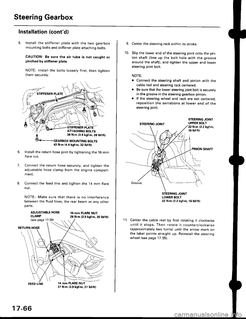
5. Install the stiffener plate with the two gearbox
mounting bolts and stiffener plate aftaching bolts.
CAUTION: Be sure the air tube is not caught orpinched by stiffener plate,
NOTE: Install the bolts loosely first, then tighten
them securely.
7.
8.
6.Install the return hose joint by tightening the l6 mm
flare nut.
Connect the relurn hose securely, and tighten the
adjustable hose clamp from the engine compart-ment.
Connect the feed line and tighten the 14 mm flare
nut.
NOTE: Make sure that there is no interference
between the fluid lines, the rear beam or any otherparts.
ADJUSTABLE HOSECLAMP(see page 17-39)
16 mm FLARE NUT28 N.m {2.9 ksl.m. 20 lbf.ft)
RETURN
1a mm FLARE NUT37 N.m (3.8 kg{.m, 27 lbt.ftl
ATTACHING AOLTS38 N.m 13.9 kgf.m, 28 lbf.ftl
MOUNTING BOLTS(} N.m (4.a kgt m, 32 lbf.ftl
17-66
9.Center the steering rack within its stroke.
Slip the lower end of the steering joint onto the pin-
ion shaft (line up the bolt hole with the groove
around the shaft), and tighten the upper and lower
steering joint bolt.
NOTE:
. Connect the steering shaft and pinion with the
cable reel and steering rack centered.. Be sure that the lower steering joint bolt is securely
in the groove in the steering gearbox pinion.
. lf the steering wheel and rack are not centered,
reposition the serrations at lower end of the
steering joint.
10.
STEERING JOINTUPPER BOLT22 N.m (2.2 kgf.m,16 tbt.ftl
PINION SHAFT
Groove,
STEERING JOINTLOWER BOLT22 N.m (2.2 kgt.m, 16lbtttl
11.Center the cable reel by first rotating it clockwise
until it stops. Then rotate it counterclockwise(approximately two turns) until the arrow mark onthe label points straight up. Reinstall the steeringwheel (see page 17 35).
Page 1155 of 2189
t
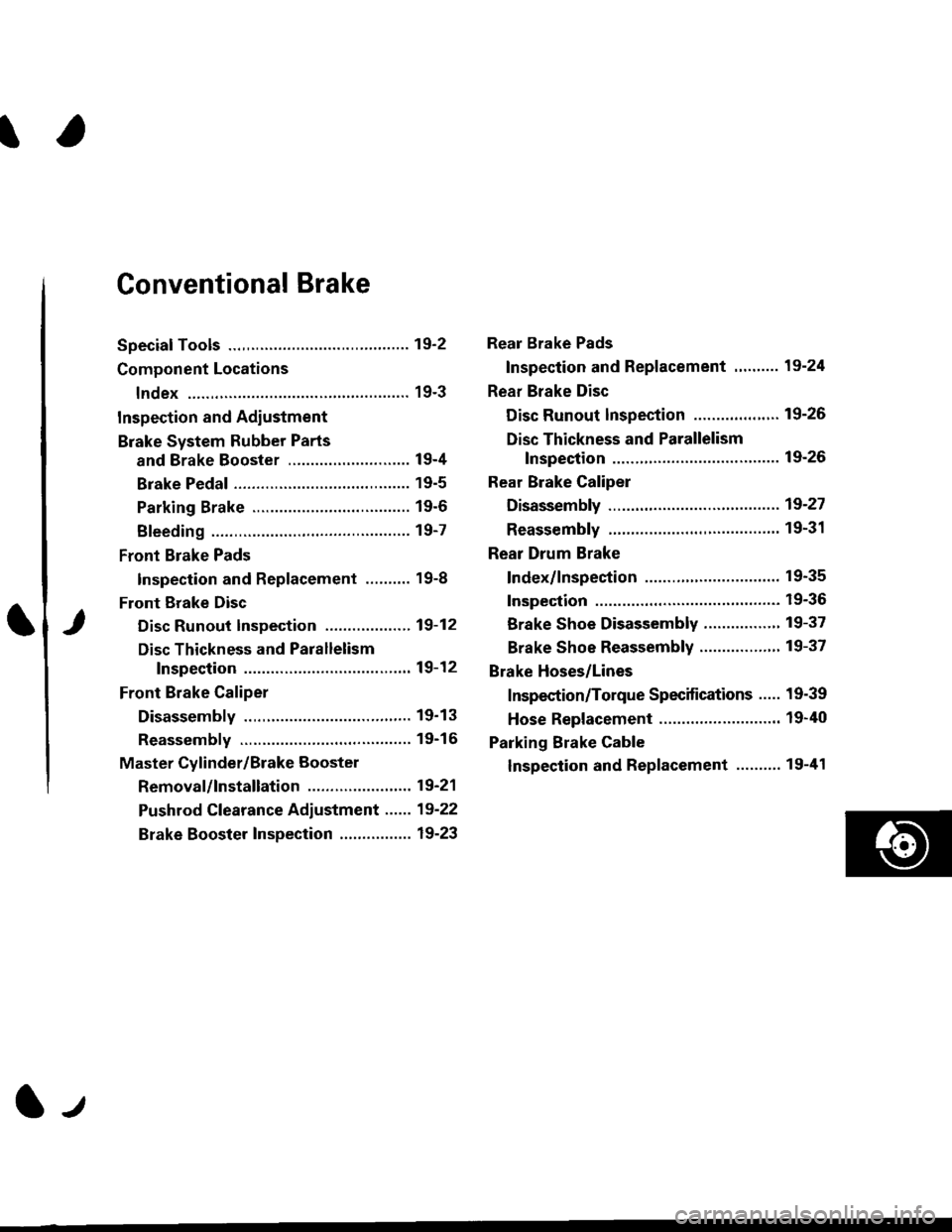
Conventional Brake
Speciaf Tools .............19'2
Component Locations
lndex ................ ...... 19-3
Inspection and Adiustment
Brake System Rubber Parts
and Brake Booster ...........,.,............. 19-4
Brake Pedal ............ 19-5
Parking Brake ........ 19-6
Bleeding ................. 19-7
Front Brake Pads
Inspection and Replacement .......... 19-8
Front Erake Disc
Disc Runout Inspection ................... 19-12
Disc Thickness and Parallelism
Inspection .......... 19-12
Front Brake Caliper
Disassembly .......... 19'13
Reassembly ........... 19-16
Master Cylinder/Brake Booster
Removal/lnstallation ....................... 19-21
Pushrod Clearance Adiustment ...... 19-22
Brake Booster Inspection ................ 19-23
Rear Brake Pads
Inspection and Replacement ,,........ 19-24
Rear Brake Disc
Disc Runout lnspection ................... 19-26
Disc Thickness and Parallelism
Inspection .......... 19-26
Rear Brake Caliper
Disassembly ...........19-27
Reassembly ........." 19-31
Rear Drum Brake
Index/lnspection .............................. 19-35
Inspection ....,.,....... 19-36
Brake Shoe Disassembly ..............." 19-37
Brake Shoe Reassembly ...............'.. 19-37
Brake Hoses/Lines
Inspection/Torque Specifications ..... 19-39
Hose Replacement ........................... 19-40
Parking Brake Cable
lnspection and Replacement ........,. 19-41
l-l