Page 45 of 2189

Towing
lf the vehicle needs to be towed, call a professional tow-
ing service. Never tow the vehicle behind another vehi
cle with iust a rope or chain lt is very dangerous'
Emergency Towing
There are three popular methods of towing a vehicle:
Flat-bed Equipment - The operator loads the vehicle on
the back of a truck. This is the best way of transporting the
vehicle.
Wheel Lift Equipment - The tow truck uses t\ivo pivoting
arms that go under the tires {front or rear} and lifts them
off the ground. The other two wheels remain on the
ground.
Sling-type Equipment - The tow truck uses metal cables
with hooks on the ends. These hooks go around parts of
the frame or suspension, and the cables lift that end of
the vehicle off the ground The vehicle's suspension and
body can be seriously damaged if this method of towing
is attemDted.
lf the vehicle cannot be transported by flat-bed. it should
be towed with the front wheels off the ground lf due to
damage, the vehicle must be towed with the front
wheels on the ground, do the following:
lvlanual Transmission and CW
. Release the parking brake
. Shift the transmission to neutral (CW to E position)'
Automatic Transmission
. Release the Parking brake.
. Sta rt the engine.
. Shift to LDll position, then E position.
. Turn oif the engine
CAUTION;
o lmploper towing preparation will damage ihe tfans-
mission. Follow the above procedute exaqtly lf you
cannot shift the tlansmission or start the engino
laulomatic transmissionl, yout vehicle must be trans-
ported on a flat-bed.
. lt is best to tow the vehicle no farther than 50 mil€s
(80 km), and ksop thE speed below 35 mph (55 km/hl
. Trying to lift 01 tow your vehicle by tho bump€F will
caus€ setious damagg. Ths bumpers are not dEigned
to supportthe vshicle's weigh.
tJO
1-43
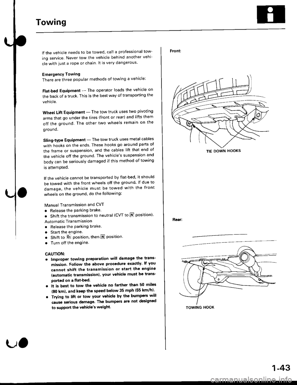
Front:
Rear:
TIE DOWN HOOKS
TOWING HOOK
Page 570 of 2189
lllustrated Index
\
NOTE:
. Whenever the transmission is removed, clean and grease the release bearing sliding surface
. lf the parts marked with an asterisk (*) are removed, the clutch hydraulic system mustbe bled (seepage 12-6)
. Inspect the hoses for damage, leaks, interference, and twisting
'RESERVOIF TANK
ASSIST SPRING
LOCK PIN
5x1,0mm9.8 N.m (1.0 kgf.m,7.2 tbtftl*CLUTCH LINE15 N.m {1.5 kgJ m,11 tbt.ft)
RELEASE BEARINGRemoval/lnspection, page 12-1 1Installation, page 12-'12
*CLUTCH MASTER CYLINDERRemoval/lnstallation, page 12 5
6x1.0mm9.8 N.m (1.0 kgf.m,7.2 tbf.ft)
FLYWHEELInspectaon, page 12IReplacement, Page 12-9
CLUTCH DISCRemoval/lnspection, page 1 2-8
lnstallation, page 12-'10
'12 x 1.0 mm118 N.m {12.0 kgt'm,86.8lbfft)
PBESSURE PLATEBemoval/lnspection, page 12 7Installation, page 12''10
8 x 1.25 mm22 N m (2.2 kgf.m, 16lbf ft)
ISLAVE CYLINDERRemoval/lnstallation, page 12_6
12-3
Page 588 of 2189

Transmission Assembly
Removal(cont'd)
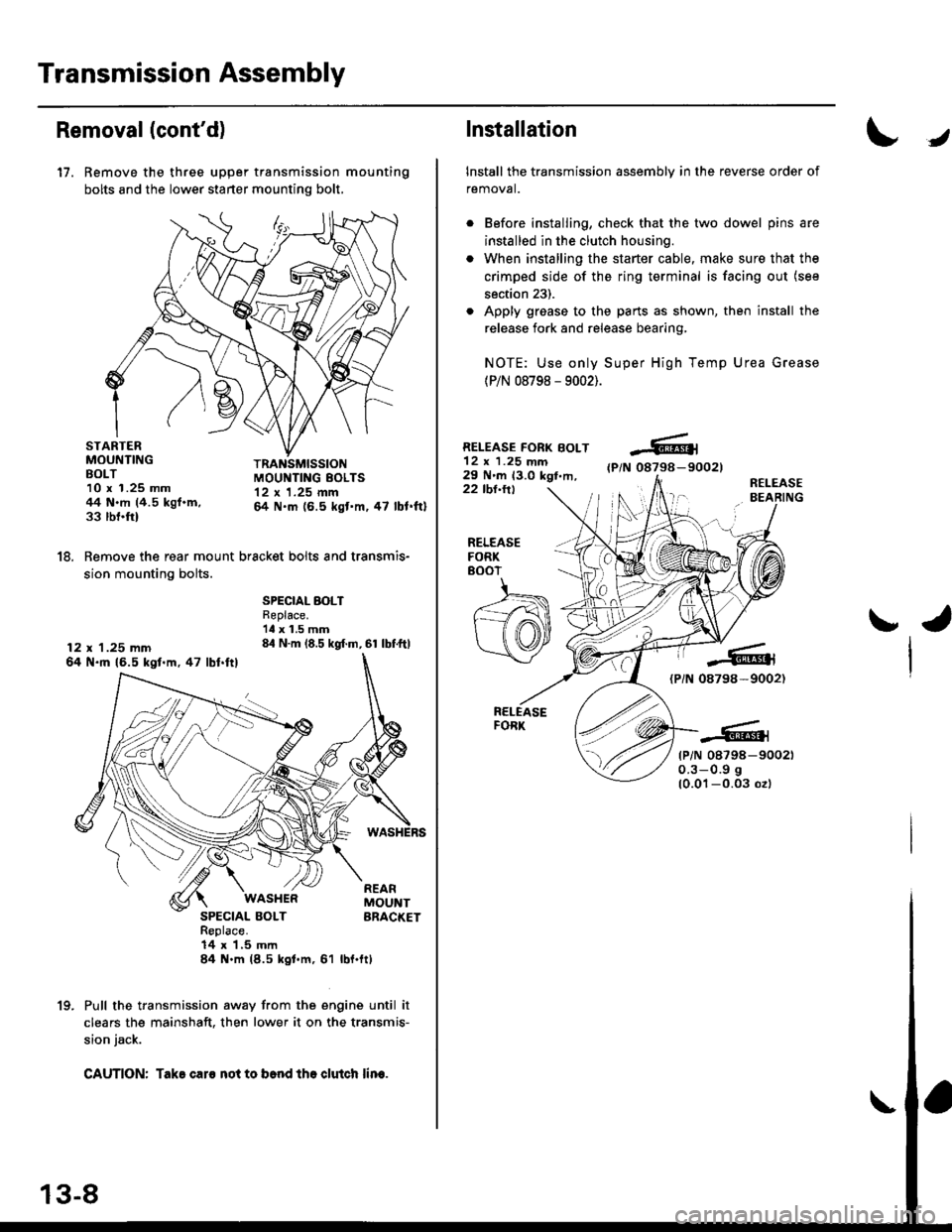
17. Remove the three upper transmission mounting
bolts and the lower starter mounting bolt,
STARTERMOUNTINGBOLT10 x 1.25 mm44 N.m (4.5 kgf.m,33 rbnftl
TRANSMISSIONMOUI{TING EOLTS12 x 1.25 mm& N.m (6.5 kgt'm,47 lbl.ftl
18. Remove the rear mount bracket bolts and transmis-
sion mounting bolts.
12 x 1.25 mm64 N.ft 16.5 kgl.m,47 lbl.ftl
SPECIAL BOLTReplace.'ll x 1.5 mm84 N.m (8.5 kgf.m, 61 lbf.ftl
SPECIAL BOLTReplace.14 x 1,5 mln84 N.m (8.5 kgl.m, 61
WASI{ERREARMOUNTBRACKET
rbl.ftt
Pull the transmission away from the engine until it
clears the mainshaft. then lower it on the transmis-
sion jack.
CAUTION: Take caro not to b6nd tho clutch lin€.
1(|
Installation
Install the transmission assembly in the reverse order of
removal.
Before installing, check that the two dowel pins are
installed in the clutch housing.
When installing the starter cable, make sure that the
crimped side of the ring terminal is facing out (see
section 23).
Apply grease to the parts as shown, then install the
release fork and release bearing,
NOTE: Use only Super High Temp Urea Grease
(P/N 08798 - 9002).
RELEASE FORK BOLT12 x 1.25 mm29 N'm 13.0 kgt,m,(P/N 08798-90021
22 tbl.ttlR€LEASEBEARING
J
RELEASEFORK8()07
ra
{PiN 08798-9002)
tP/N 08798-900210.3-0.9 g
10.01-0.03 ozl
Page 590 of 2189
lllustrated lndex
!
Refer to the drawing below for transmission disassembly/reassembly,
Clean all the parts thoroughly in solvent and dry with compressed air.
I luuricate attthe parts with oil before reassembty.
NOTE:
. This transmission uses no gaskets betvveen the major housings; use liquid gasket (PiN 08718-0001 or08718-0003)
(see page 13-41).
. Always clean the magnet @ whenever the transmission housing is disassembled.
. Inspect all the bearings for wear and operation.
a6_
'%/t'*.
k+-o
-{-g}.-_a
13-10
Page 632 of 2189

Transmission Assembly
lnstallation
Install the transmission assembly in the reverse order of
removal.
. Before installing, check that the two dowel pins are
installed in the clutch housing.
. When installing the starter cable. make sure that the
crimped side of the ring terminal is facing out (see
section 23).
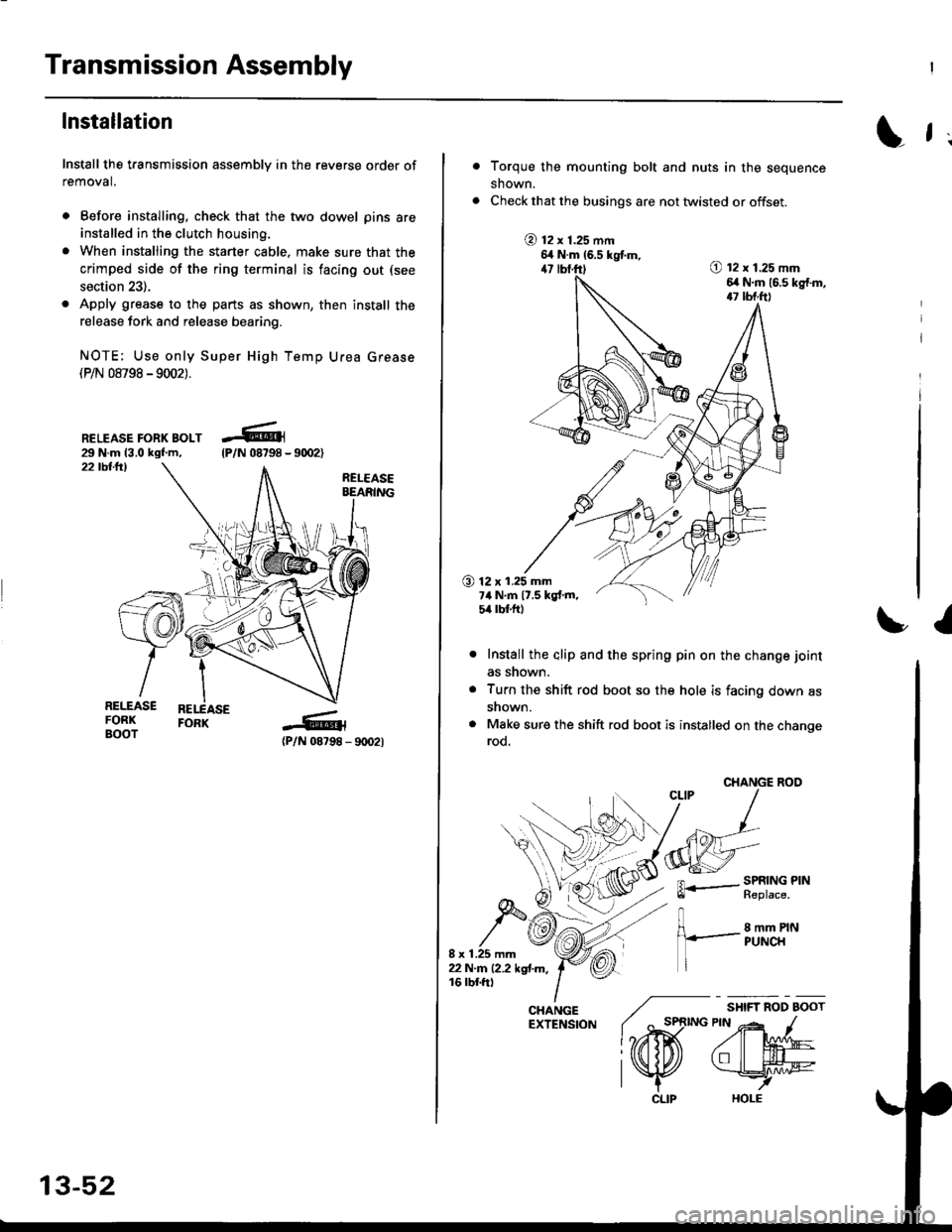
. Apply grease to the parts as shown, then install the
release fork and release bearing.
NOTE; Use only Super High Temp Urea Grease(P/N 08798 -9002).
RELEASE FORK BOLT29 N.m 13.0 kgf.m,22 tbllrl
(P/N 08798 - 9rD2l
-R1
tP/N 08798 -
13-52
CLIP
L f ;
Torque the mounting bolt and nuts in the sequence
shown.
Check that the busings are not twisted or offset.
@ t2 x 1.25 mm6,t N.m 16.5 kgtm,47 lbf.ft)O t2 x 1.25 mm6,r N.m (6.s kg{.m,17 tbf.ft)
O 12 x 1.25 mm7ilNm17.5kgf.m,5it lbt ft)
I
Install the alip and the spring pin on the change joint
as snown.
Turn the shift rod boot so the hole is facing down as
snown.
Make sure the shift rod boot is installed on the changerod.
CHANGE ROO
FL.- SPRING PINll heptace,
8 mm PINPUNCH
/ "*,*
lo,iD(
CHANGE ./EXTENSfoN ( ^ st
l?rffi
l\K
Page 634 of 2189
lllustrated Index
t
Refer to the drawing below for transmission disassembly/reassembly.
Clean all the parts thoroughly in solvent and dry with compressed air.
I Luoricate att the pans with oil before reassembly.
NOTE:
. This transmission uses no gaskets between the majorhousings; use liquid gasket (P/N 08718-0001 or08718-0003)
(see page '13-93).
. Always clean the magnet @ whenever the transmission housing is disassembled.
. Inspect all the bearings for wear and operation.
?-c
\I
ir 6d
a h Plt tia.fl
) K1T\A
l,l 1r
@rt? u
L6q
i"\^Br 'u
t@)
E,M A
#&f
o-*ffiX,
@
I
R
h"ii
'F@
,
€D
13-54
Page 826 of 2189

Mainshaft
Disassembly/lnspestion/Reassembly
NOTE:
. Lubricate all parts with ATF during reassembly..Inspectthethrustneedlebearingsandtheneedlebearingsforgallingandroughmovement,
. Before installing the O-rings, wrap the shaft splines with tape to prevent damaging the O_rings.. Locknut has left-hand threads.
LOCKNUT {FLANGE NUTI21 x 1.25 mm78 N.m (8.0 kgl.m,58 lbt.fttReplace.Left-hand threadsSNAP RINGCONICAL SPRING WASHERReolace.
lST CLUTCHASSEMBLYTHRUST WASHER
THRUST NEEOI.EBEARING
4TH GEAN
O-RINGSReplace.
THRUST WASHER
THRUST NEEDLEBEARING
MAINSHAFTCheck splines for excessivewear and oamage.Check bearing surtace for scoring,scratches and excessive wear.
BEARINGBEARINGS
THRUST NEEDLEBEABING
4TH GEAR COLLAR
2ND/4TH CLUTCHASSEMBLY
THRUST NEEDLEEEARING
2NO GEAB
NEEDLE BEABING
THRUST NEEDLEBEARING
1ST GEAR
1ST GEARCOLLAR
TRANSMISSIONHOUSING BEARING
O-RINGSReplace.
THRUST WASHER, 36.5 x 55 mmSelective part.
SEALING RINGS,35 mm
Install the sealing ringmating faces as shown,
RING,29 mm
NEEDLE BEARING
SET RING
14-148
Page 829 of 2189
Countershaft
Disassembly/lnspection/Reassembly
NOTE:
. Lubricate all parts with ATF before reassembly'
. tnrp"",,n",t -"t needle bearings and the needle bearings for galling and rough movement'
. Before installing the O-rings. wrap the shaft splines with tape to prevent damaging the O-rings
. Locknut has left-hand threads
LOCKNUT (FLANGE NUT}
23 x 1.25 mm103 N.m
{10.5 kgf'm, 75.9 lbf'tt)
Replace.Left'handlhreads
CONTCAL SPRING
WASHERReplace.
GEAR
CLUTCH
1ST GEAR
BEARING
lST GEAR COLLAR
TRANSMISSIONHOUSING BEARING
REVERSE GEAR
NEEDLEBEARING
SELECTOR
SELECTOR
4TH GEAR
NEEDLE BEARING
DISTANCE COLLAS,
28 mmSelective pa .
COUNYERSHAFTCheck splines lor excesslve
wear and damage
2'{D GEAR
THRUST NEEDLEBEARING
3RD GEAB
NEEDLE BEARING
3RD GEAR COLLAR
THRUST NEEDLE EEARING
SPLINEO WASHER
3RD CLUTCH ASSEMBLY
Check bearing surface for scoring'
scratches and excessive wear'
Replace.
1+151