Page 1293 of 2189
Hatch Trim
>:Clip locationsa>,2NOTE: Do not push thlnner clip in too far.
& ct-tp.
54d-g+-\
2. INNF
Ijy. "
\
.V ft -s---
- k-"i-t-;-a-
Replacement
CAUTION:
. Put on gloves to protect your hands.
. When prying with a flat-tip screwdrivel, wrap it with protestive tape to prevent damage.
NOTE: Take care not to bend or scratch the trim and panel.
LEFT HATCHSIDE TRIM
HATCHUPPER TRIM
Installation is the reverse of the removal procedure.
NOTE:
. lf necessary, replace any damaged clips.
. ToinstalltheAclips,pulltheinnerclipup.installtheclip,thenpushtheinnerclipuntil it'sflush
a
I
20-63
Page 1307 of 2189
Harness Wiring and Recline
Cable Locations
NOTE: When installing the seat cushion, make sure the
seat belt switch harness, connector and recline cable are
fastened correctly on the seat cushion frame'
Driver's:>: Clip locations
Passenger's (with lecline cablel:
TRACK
Seat Cover RePlacement
CAUTION: Put on gloves to protest yout hands'
NOTE: Take care not to tear the seams or damage the
seat covers.
Seat-back cover removal:
1. Release the hook, and fold back the seat-back cover'
Release all inside springs, then fold back the seat-
back cover.
Remove the headrest.
Remove the headrest guide, then remove the seat-
back cover.
lnst;llation is the reverse of the removal procedure'
NOTE: To prevent wrinkles when installing a seat-
back cover, make sure the material is stretched evenly
over the pad before securing the inside springs and
hook.
3.
(cont'd)
20-77
HEADREST
Page 1330 of 2189
Trunk Lid/Hatch
WeatherstripLicense Plate Trim
Replacement
When installing the trunk lid/hatch weatherstrip. align it
with the alignment mark on the trunk lid/hatch opening.
NOTE:
. Make sure there are no wrinkles in the weatherstrip.
. Check for water leaks.
2DllDi
STEEI.CORE
3D:
ALIGNMENTMARK (2Dl4D)
ALIGNMENT MARK
WEATHERSTRIP
ALIGNMENT MARK
BODY
\
20-100
Replacement
CAUTION: Put on glov€s to plotest your hands.
NOTE: Take care not to scratch the trunk lid/hatch.
1. Remove the license plate.
2, 3D: Remove the hatch trim panel (see page 20-63).
3. Remove the nuts and clips, and detach the clip, then
remove the license plate trim.
NOTE: Take care not to drop the nuts inside the trunk
lid/hatch.
a: Nut locations,2
6fi\5x0.8mm Irvr?// 1,8 N.m {0.18 kst.m,l- j llrftl ,/
>: Clip locations,
InA
aa# )
-,/
Installation is the reverse of the removal orocedure.
NOTE: lf necessary, replace any damaged clips.
Page 1332 of 2189
Side Window MoldingsRoof Molding
Replacement
CAUTION: Put on glovos to protect your hands.
NOTE:
. Take care not to scratch the body
. Remove the screw, and pull th€ side window molding
by hand.
>: Clip locationsA>,13
Installation is the reverse of the removal procedure.
NOTE: lf necessary, replace any damaged clips.
1l
)
A
>: Screw locations,
*@
MOLOING
\
20-102
Replacement
CAUTION: When prying with a flat-tip screwdriver, wrap
it with protestive taps to prevent damage, and use pro-
toctiv€ tape on the body.
NOTE: Take care not to scratch the bodv.
WINDSHIELOMOLDING
Installation is the reverse of the removal procedure.
NOTE:
. Take care not to damage the windshield molding.. Make sure the roof molding is installed securely.
K
PINlBody side)
I
)
Page 1420 of 2189

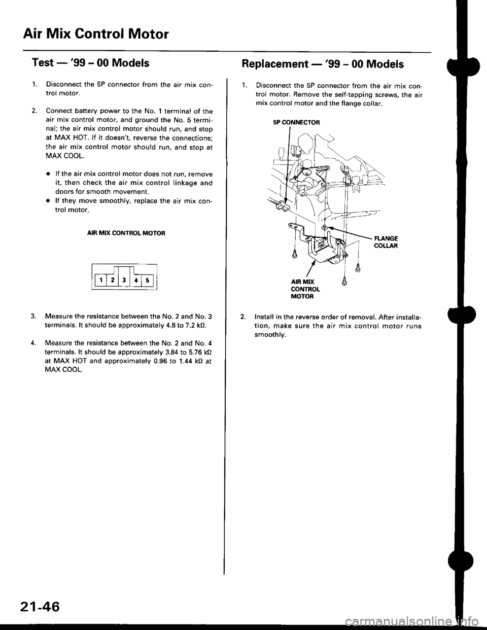
Air Mix Gontrol Motor
't.
Test -'99 - 00 Models
Disconnect the 5P connector from the air mix con-
trol motor.
Connect battery power to the No. 1 terminal of the
air mix control motor, and ground the No. 5 termi,
nal; the air mix control motor should run, and stop
at MAX HOT. lf it doesn't, reverse the connections;
the air mix control motor should run, and stop at
MAX COOL.
lf the air mix control motor does not run, remove
it, then check the air mix control linkage and
doors for smooth movement.
lf they move smoothly, replace the air mix con-
trol motor.
AIR MIX CONTROL MOTOR
Measure the resistance between the No.2 and No.3
terminals. lt should be approximately 4.8 to 7.2 kO.
Measure the resistance between the No. 2 and No. 4
terminals. lt should be approximately 3.84 to 5.76 kO
at MAX HOT and approximately 0.96 to 1.44 kO at
MAX COOL.
21-46
5P OONNECYOB
Replacement -'99 - 00 Models
1, Disconnect the 5P connector from the air mix con-
trol motor. Remove the self-tapping screws, the airmix control motor and the flange collar.
CONTROLMOTOR
Install in the reverse order of removal. After installa-
tion, make sure the air mix control motor runs
smoothly.
Page 1421 of 2189

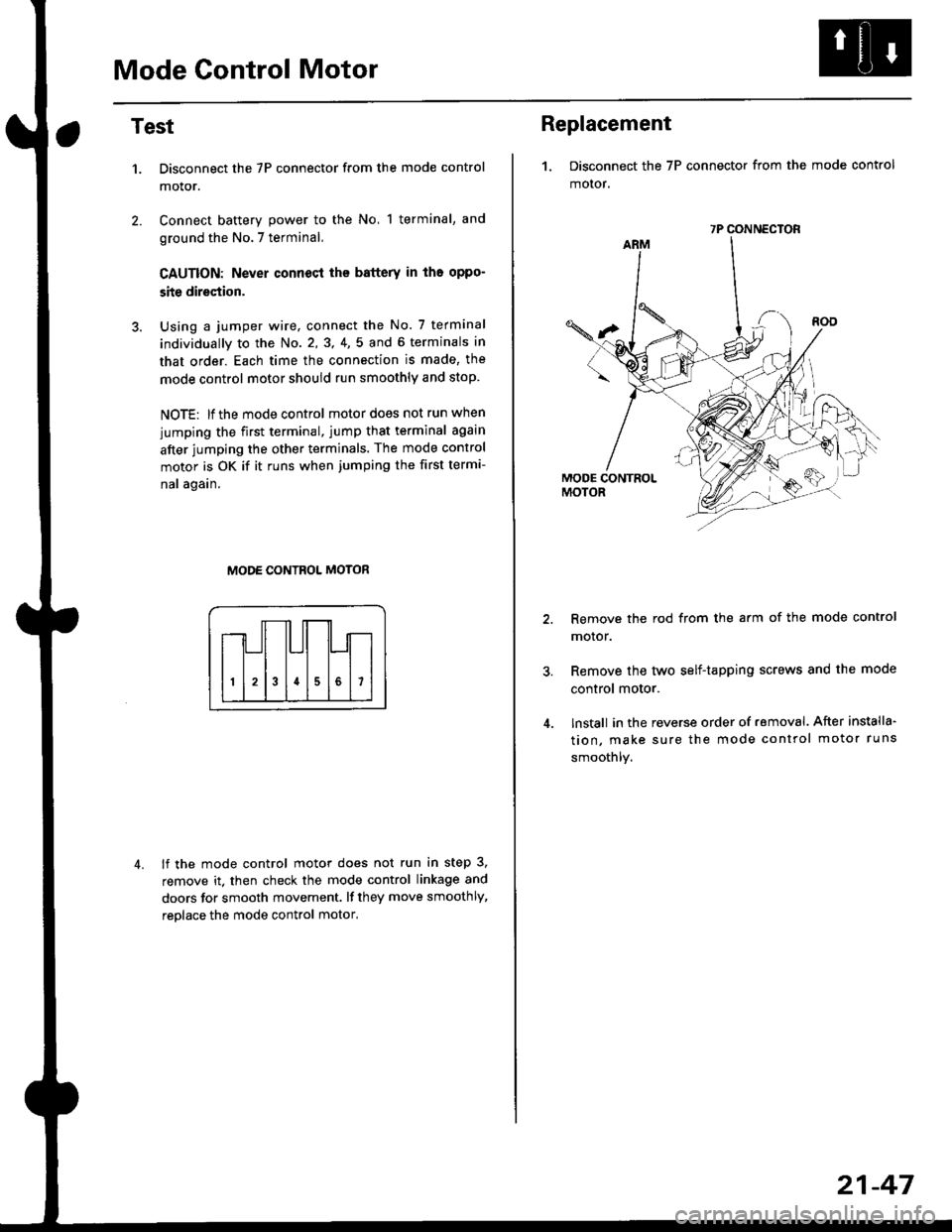
Mode Control Motor
2.
Test
1.
4.
Disconnect the 7P connector from the mode control
motor.
Connect battery power to the No, 1 terminal, and
ground the No.7 terminal,
CAUTION: Never connecl the battery in iho oppo-
site direction.
Using a jumper wire, connect the No. 7 terminal
individually to the No. 2,3, 4,5 and 6 terminals in
that order. Each time the connection is made, the
mode control motor should run smoothly and stop.
NOTE: lf the mode control motor does not run when
jumping the first terminal, jump that terminal again
after jumping the other terminals. The mode control
motor is OK if it runs when jumping the first termi-
nal again.
MODE CONTROL MOTOR
lf the mode control motor does not run in step 3,
remove it. then check the mode control linkage and
doors for smooth movement. lf they move smoothly,
reolace the mode control motor,
Replacement
1. Disconnect the 7P connector from the mode control
motor,
Remove the rod from the arm of the mode control
motor.
Remove the tyvo self-tapping screws and the mode
control motor.
lnstall in the reverse order of removal. After installa'
tion, make sure the mode control motor runs
smoothly.
7P CONNECTOR
21-47
Page 1422 of 2189

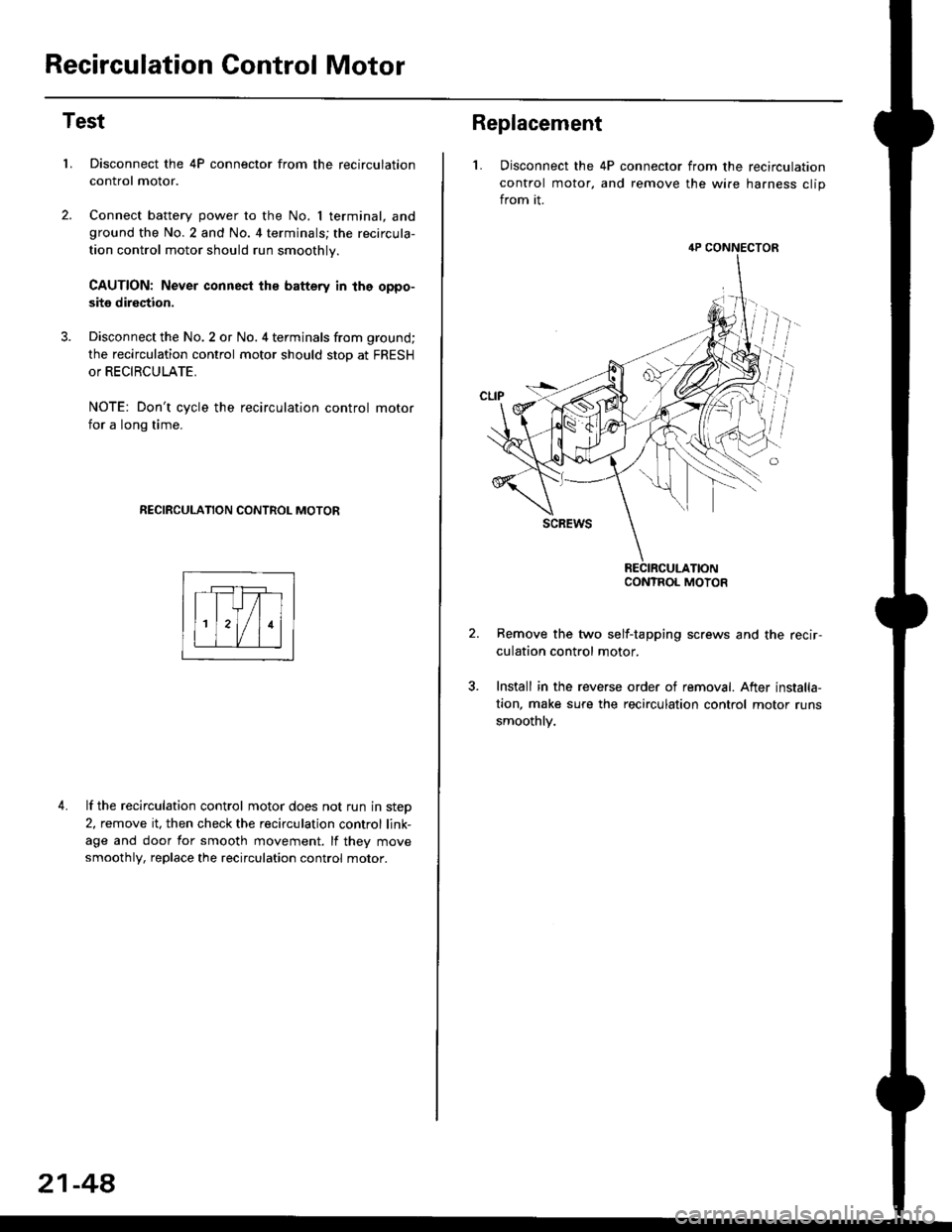
Recirculation Control Motor
Test
LDisconnect the 4P connector from the recirculation
control motor.
Connect battery power to the No. I terminal, andground the No.2 and No. 4 terminals; the recircula-
tion control motor should run smoothly.
CAUTION: Never connest ths battery in the oppo-
site direction.
Disconnect the No. 2 or No. 4 terminals from ground;
the recirculation control motor should stop at FRESH
or RECIRCULATE.
NOTE: Don't cycle the recirculation control motor
for a long time.
RECIRCULATION CONTROL MOTOR
4. lf the recirculation control motor does not run in step
2, remove it, then check the recirculation control link-
age and door for smooth movement. lf they move
smoothly, replace the recirculation control motor.
21-48
Replacement
L Disconnect the 4P connector from the recirculation
control motor, and remove the wire harness clip
from it.
Remove the two self-tapping screws and the recir-
culation control motor.
Install in the reverse order of removal. After installa,
tion, make sure the recirculation control motor runs
smoothly.
4P CONNECTOR
CONTROL MOTOR
Page 1451 of 2189

Recovery
Use only service equipment that is U.L.-listed and is cer-
tified to meet the requirements of SAE J2210 to remove
HFC-134a (R-134a) from the air conditioner system
CAUTION: Exposure to air conditioner relrigerant and
lubricant vapor or mist can illitate eyes, noss and
throat. Avoid breathing the ail conditioner refrigerant
and lubricant vapor or mist.
lf accidental system discharge occurs, ventilate work
area before resuming service.
R-134a service equipment or vehicle air conditioner sys-
tems should not be pressure tested or leak tested with
compressed air.
!@@ some mixtures ot air and R'13'[a havo been
strown to be combustiblg at elevated pressures and Gan
resuh in fire or explosion causing iniury or property dam-
age, Never use compressed air to pressure test R-134a
service equipment or vehicle air conditioner systems.
Additional health and safetv information may be obtained
from the refrigerant and lubricant manufacturers.
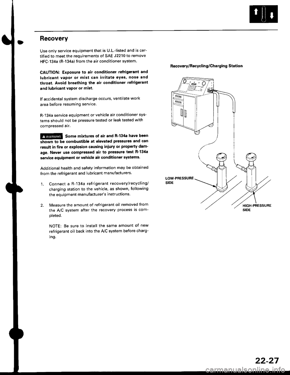
1, Connect a R-'134a refrigerant recove rylrecycling/
charging station to the vehicle, as shown. tollowing
the equipment manufacturer's instluctions.
2. Measure the amount of refrigerant oil removed from
the A/C svstem after the recovery process is com-
pleted.
NOTE: Be sure to install the same amount of new
refrigerant oil back into the Iy'C system before charg-
tno.
R€covery/Recyclin g/Cha19ing Station
22-27