1996 HONDA CIVIC Stall test
[x] Cancel search: Stall testPage 550 of 2189

\
'99 - 0O modols except Dl5Y5 engine with M/T:
rFo45'::n":"tooIindicatesDiagnosticTroub|ecode(DTc)P0453:Ahighvo|tageprob|emintheFUelTankPressure
Wire side of temale terminals
FUEL TANKPRESSUNE SENSOR
SUB.HARNESS6P CONNECTOR {C574 (C568)}}
vcc2{YEL/BLUI
sG2IGRN/BLK)
Wire side of female terminals
PTANK{LT GRNI
(cont'd)
11-281
ECM/PCM CONNECTOR A {32P)
PTANK {LT GRN)
The MIL has been reported on.
DTC P0453 is stored.
Check the vacuum lines:
Check the vacuum lines ot the
fuel tank pressure sensor for mis-
routing, leakage, breakage and
clogging.
Are the vacuum lines OK?
Problem verilication:1. Do the ECM/PCM Reset Proce-
du re,2. Remove the fuel fill caP
3. Turn the ignition switch ON (ll).
4. Monitor the FTP Sensor volt'
age with the Honda PGM
Tester, or measure voltage
between body ground and
ECM/PCM connector terminalA.29.
lntermittent failuro. svstem b OK
at this time. Check for Poor con_
noctions or loo3€ wire3 at C131
{located under tight side of dash),
C4Ol {located above underdash
fuse/relay boxl, C57{ (C5681'
llocaled unde. access Panell,C792 {fuel tank Pressure sensorl
aod ECM/PCM.
ls there approx.2.5 V?
Ch€ck for an open in the wira
{SG2line):1. Turn the ignition switch OFF.
2. Reinstall the fuel fill caP
3. Remove the access Panellrom the floor.
4. Disconnect the fuel tank Pres-sure sensor sub-harness 6P
5. Turn the ignition switch ON (ll)
6, At the access Panelside, mea-
sure voltage between the fuel
tank pressure sensor sub_har-
ness 6P connector termlnals
No.5 and No.6.
Repair open in the wire between
the fueliank Pres3ure 3ensor and
ECM/PCM {Cl8).ls there approx.5 V?
Check lor an oPen in the wire
{PTANK linel:At the access Panel side, mea
sure voltage between the fuel
tank pressure sensor suo_harness
6P connector No. 2 terminal and
No. 6 terminal.
ls there approx. 5 V?
(To page 11.282)
Page 563 of 2189

Emission Control System
Evaporative Emission (EVAPI Controls (cont'd)
Evaporative Emission (EVAPI Two Way Valve Testing
l'96 DIGYS engine lcoupel,'97 Dl6Y7 engine (coupe: KL
model, sedan: KL (LX) modoll,'97 Dl6Y8 engine {coup€:
alt models, sedan: KL model, '98-all modelsll:
1. Remove the fuel fill cap.
2. Remove the vapor line from the EVAP two way
valve. and connect it to a T-fitting from a vacuum
gauge and a vacuum pump as shown.
VACUUM/PRESSURE
IJ
f96 D16Y5 engine,'96 D16Y7 engine,'96 D16Y8 ongine
(sedanl,'97 D16Y5 engine,'97 Dl6Y7 engine {coupe: KA,
KC models, sedan: KA, KC, KL {DX} models, hatchback:
all modsls),'97 D16Y8 engine {sedan: KA, KC models}l:
1. Remove the fuel fill cap,
2. Remove the vapor line from the EVAP two way
valve on the fuel tank, and connect it to a T-fitting
from a vacuum gauge and a vacuum pump as
snown.
VACUUM/PRESSURE GAUGE,0 - 4 in.Hg07JAZ - 0010008VACUUMPUMP/GAUGE.0 -30 in.HgA973X-041 -XXXXX
Apply vacuum slowly and continuously while watch-
ing the gauge. The vacuum should stabilize momen-
tarily at 0.8 - 2.1 kPa (6 - 16 mmHg, 0.2 - 0.6 in.Hg).
lf the vacuum stabilizes (valve opens) below
0.8 kPa {6 mmHg, 0.2 in.Hg) or above 2.1 kPa
(16 mmHg, 0.6 in.Hg), install a new valve and retest.
Move the vacuum pump hose from the vacuum fit-
ting to the pressure fitting, and move the vacuum
gauge hose from the vacuum side to the pressure
side as shown.
Slowlv pressurize the vapor line while watching the
gauge. The pressure should be stabilize momentari
ly above 1.0 kPa (8 mmHg. 0.3 in.Hg).
. lf the pressure momentarily stabilizes (valve
opens) above '1.0 kPa (8 mmHg, 0.3 in.Hg), the
valve is OK.
. lf the pressure stabilizes below 1.0 kPa (8 mmHg,
0.3 in.Hg), install a new valve and retest.
Apply vacuum slowly and continuously while
watching the gauge. The vacuum should stabilize
momentarily at 0.7 - 2.0 kPa (5 - 15 mmHg, 0.2 - 0.6
in.Hg ).
lf the vacuum stabilizes (valve opens) below
0.7 kPa (5 mmHg,0.2 in.Hg) or above 2.0 kPa
(15 mmHg, 0.6 in.Hg), install a new valve and retest.
Move the vacuum pump hose from the vacuum fit-
'l'
4.
5.
ting to the pressure fitting, and move the
gauge hose from the vacuum side to the
side as shown.
PRESSURESIDE
Slowly pressurize the vapor line while watching the
gauge. The pressure should stabilize at 1.3 - 4.7 kPa
(0 - 35 mmHg, 0.4 - 1.4 in.Hg).
. It the pressure momentarily stabilizes (valve
opens) at 1.3 - 4.7 kPa (10 - 35 mmHg, 0.4 - 1.4
in. Hg), the valve is OK.
. lf the pressure stabilizes below 1.3 kPa (10 mmHg,
0.4 in.Hg) or above 4.7 kPa (35 mmHg. 1.4 in.Hg),
install a new valve and retest.
vacuum
pressure
GAUGE0- 4 in.Hg
T-FITTINGT-FITTING
11-294
\,
Page 564 of 2189

\
Evaporative Emission (EvAPl Two Way Valve T6ting
'99 - 00 modols:
'L Remove the fuel tank (see page 11-242).
2. Remove the vapor line {rom the EVAP two way
valve (located above the EVAP control canister), and
connect it to a T-fitting from vacuum gauge and
vacuum pumo as snown,
VACUUM/PRESSUREGAUGE0 - il in.Hg07JAZ - 001(x)08
ry(L
"*'"""_,";f1
T.FITTING
Apply vacuum slowly and continuously while watch-
ing the gauge.
The vacuum should stabilize momentarily at 0.8 -
2.1 kPa {6 - 16 mmHg, 0.2 - 0.6 in.Hg).
lf the vacuum stabilizes (valve opens) below
0.8 kPa (6 mmHg, 0.2 in.Hg) or above 2.1 kPa
(16 mmHg, 0.6 in.Hg), install a nsw valve and retest.
Move the vacuum pump hose from the vacuum fit-
ting to the pressure fitting, and move the vacuum
gauge hose from the vacuum side to the pressure
side as shown.
GAUGE,0 - 30 in.Hg4973X - (Xl -
xxxxx
J.
5. Slowly pressurize the vapor lin€ while watching the
gauge.
The pressure should be stabilize momentarily
above 1.0 kPa (8 mmHg, 0.3 in.Hg).
. lf the pressure momentarily stabilizes (valve
opens) above 1.0 kPa (8 mmHg, 0.3 in.Hg), the
valve is OK.
. ll the pressure stabilizes below 1.0 kPa (8 mmH9,
0,3 in,Hg), install a new valve and retsst.
(cont'd)
11-295
Page 565 of 2189

Emission Gontrol System
Evaporative Emission (EVAP) Controls (cont'dl
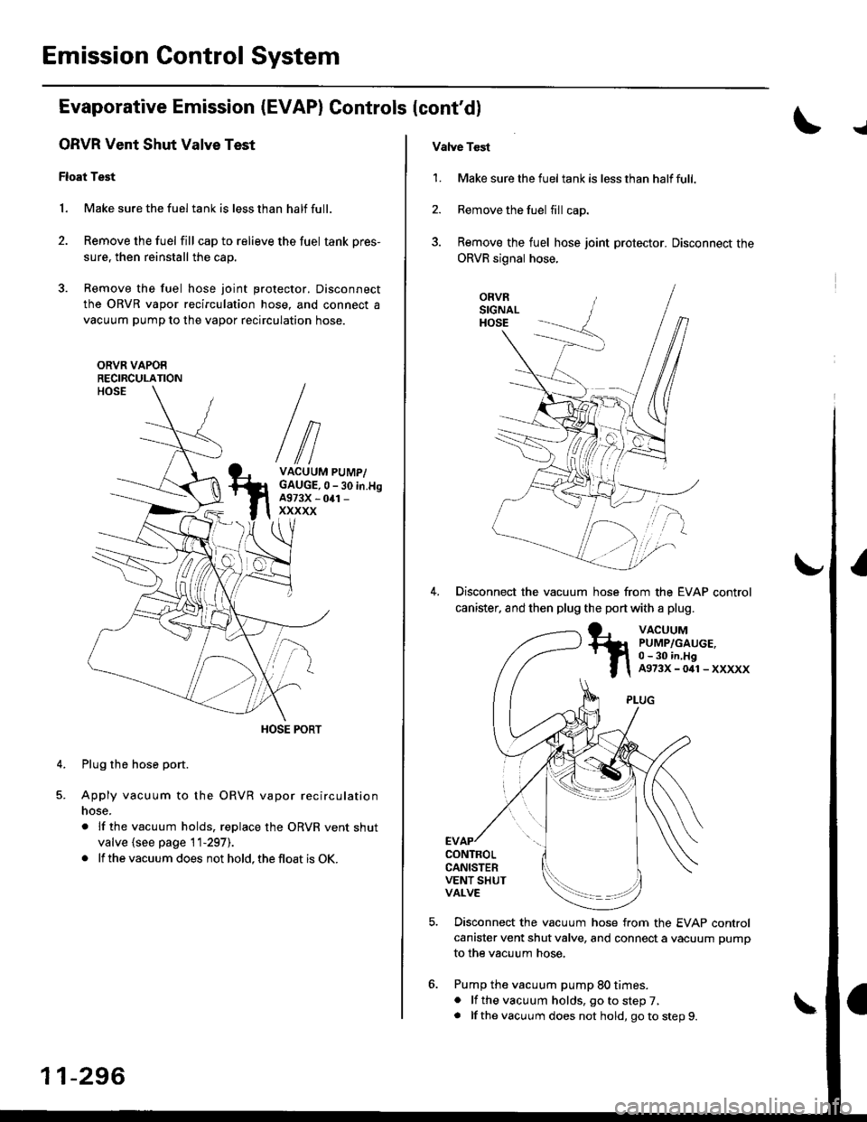
ORVR Vent Shut Valve Test
Float Test
1. Make sure the fuel tank is less than half full.
2. Remove the fuel fill cap to relieve the fuel tank pres-
sure, then reinstall the cap.
3. Remove the fuel hose joint protector. Disconnect
the ORVR vapor recirculation hose, and connect a
vacuum pump to the vapor recirculation hose.
ORVR VAPOERECIRCULATION
VACUUM PUMP/GAUGE,0 - 30 in.H9A973X - 041 -
xxxxx
Plug the hose port.
Apply vacuum to the ORVR vapor recirculation
nose.
. lf the vacuum holds, replace the ORVR vent shut
valve {see page 11-297).
. lf the vacuum does not hold, the float is OK.
4.
11-296
Vatve Tcst
1. Make sure the fueltank is lessthan halffull.
2. Remove the fuel fill cap.
3. Remove the fuel hose joint protector. Disconnect the
ORVR signal hose.
ORVRSIGNALHOSE
Disconnect the vacuum hose from the EVAP control
canister. and then plug the port with a plug.
VACUUMPUMP/GAUGE,0 - 30 in,HgA973X-041-XXXXX
CONTROLCANISTERVENT SHUTVALVE
Disconnect the vacuum hose from the EVAP control
canister vent shut valve, and connect a vacuum pump
to the vacuum hose,
Pump the vacuum pump 80 times.. lf the vacuum holds, go to step 7,. lf thevacuum does not hold, goto step9.
Page 583 of 2189

MaintenanceBack-up Light Switch
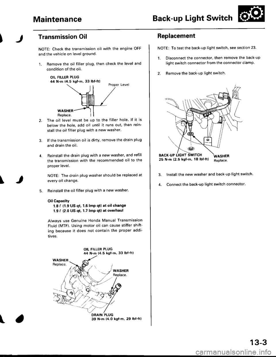
Transmission Oil
NOTE: Check the transmission oil with the engine OFF
and the vehicle on level ground.
1. Remove the oil filler plug, then check the level and
condition of the oil.
OIL FILLER PLUG/14 N.m (4.5 kgl.m,33 lbl.ft)Proper Level
4.
WASHERReplace.
The oil level must be up to the filler hole. lf it is
below the hole, add oil until it runs out. then rein-
stall the oil filler plug with a new washer.
lf the transmission oil is dirty, remove the drain plug
and drain the oil.
Reinstall the drain plug with a new washer, and refill
the transmission with the recommended oil to the
proper lever.
NOTE: The drain plug washer should be replaced at
every oil change.
Reinstall the oil filler plug with a new washer.
OilCapacity
1.8 f (1.9 US qt. 1.6 lmp qtl at oil change
1.9 { (2.0 US $, 1.7 lmp qt) at overhaul
Always use Genuine Honda Manual Transmission
Fluid {MTF). Using motor oil can cause stiffer shift-
ing because it does not contain the proper addi-
t|ves.
\
\
Replacement
NOTE: To test the back-up light switch, see section 23
1. Disconnect the connector, then remove the back-up
light swirch connector from the connector clamp.
2. Remove the back-up light switch.
25 N.m (2.5 kgf'm, 18lbf'ltl
Install the new washer and back-up light switch
Connect the back-up light switch connector.
ASHER
13-3
Page 679 of 2189

Automatic Transmission
Special Tools ......... .....'."".'-.-.' 14'2
Description .,....................-...... 14-3
power Flow ......,................. 14"6
Elestronic Control System .... . ................'..'.'.. 14-13
Hvdraulic Control .....'......" 1'l-19
Hydraulic F|ow...... .'.'.".'....11-21
Lock-up System '............ ... t/t'33
Electrical System
Component Locations....,.............'......'.............'.,. 14'39
PCM Circuit Diagram
lA/T Control Syst€m: '96 - 98 Models) .........'.. 1/t-40
PCM Tarminal Volt8ge/Measuring Condhions
{'96 - 98 ModeblA/T Control System ............
PCM Circuit Disgram(A/T Conlrol System: '99 - 00 Modsls) '..........' 14-44
PCM Terminal Voltage/Measuring Conditions('99 - 00 Models)A/T Control System ...
Troubleshooting Proceduros ....
Symptom-to-ComPonent Chari
Efectricaf SFiem - '96 - 98 Models '..-.-..."'.'..11-52
Eloqtrical System -'99 - 00 Modols ... .........". 1+54
EleclricatTroubl$hooting ('96 - 98 Models)
Valve Body
Repair .................... ........'.... 14-139
Valve
Assembly
ATF Pump
1,1-1i10
Inspection ...........'.......... 14-141
Main Valvs Body
Disass€mbf y/lnspoction/R.sssembly .'.'.'.'.. -. -. 1 1-1 12
Secondsry Valve BodY
Disa$embfy/lnspoction/Rsassembly ......'.'.'.'. 11-111
Regulator Valve Body
Disa$embly/lnspoction/Rea3sembly ..........'... 14-1{5
Servo Body
Disassombly/lnsp€ction/Reassembly .".'........ 14-146
Lock-up Valv6 Body
Dis$s.mbf y/ln3poction/Rea$embly .'.. -. -..'.'.' 1 1-1 17
Mainsh!ft
Dkassembly/lnep€ction Reassembly ..'...'........ 14'148
Inspoction .............'..........'. l it-149
Countsrshaft
Disa$embly/lnspeqtion/Rea3sembly .......'...'.. 1a-l51
Dba$ombly/Re$s.mblY11-152
til-46
I rl-48
Troubleshooting Flowcharts
Electrical Troubleshooting ('9!t - 00 Models)
Troublsshooting Flowchart3
Lock-up Control Solenoid vslvo A/B AssemblY
RePlacoment
Shift Cont.ol Solenoid Valve A/B A3sembly
Inspestion
Ona-way Clutch
Disassembh/lrupoction/Rca$embly .. "'........ l4-155
Clutch
lllustlttcd Ind.x {A48A, B4RA Transmlssion) ..' 14-156
tustr.tod Index (MrnA Transmi$ionl ............ til-158
...................... 14-153
L
14-56
1+81'
14-105
1+105
Replacoment ......
Mainshaft/Countorshaft Spo€d Sonsors
Replacemsnt ......'."'........... lit'108
Hydraulic System
Symptom-to-Componeni Chart
Hydraulic Sydemr+109
t4-113
1+116
11-117
Rea$emblY
14-106 Difforrr ial
llhdraied Index........ t4-156
B.ckhrh ln3poction. 14-167
Boaring Roplacemont..-..........11-167
..... 14-108 Diftrrsniial Carrior Repl8cemeni .'.-.............'...' lil-168
Oil Sall Romovalt4-t 59
Oil Soal ln3tallstion/Sidc Clearance'......'.....'... 1'l'169
Torqua Convertcr Housing Boarings
Mlin3haft Besring/Oil Scal Roplac.ment ."..'.. lil-172
Counio6hatt Betring R.plscem.nt ..'...... ....... 14-173
Test.....,......14-106
14-107
14-160
11-162
11-171
11-175
Replacement
Test .....,.,..........
Road Te3t
Linear Solenoid AsssmblY
Stall Speed
lllustrated Indax
Transmission/End Cover'. ....
Transmission Hou3ing,.............'.'......'....""..-.-.. 11-128
Torque Conve.ter Housing/Valvo Body ........... 14-130
End Cover
14-itB Park Stop
1+119 In3pection/Adiustmsnt...'......'.'............'...."""'14-175
Transmbgion
Reassombly
11-122 Torquo Convertet/Drivr Plsie ............'.'............'.. . l4-182
Transmission
11.726 Inrtallation
Tranlmission Housing Boarings
Msinsh.ft /CounteEhaft Bearings
B!pltcomgnt
Rcvo.3s ldlor Gear
lnrtallation
Cooler Flushing ..
Shift Cabls
Test
Fluid Level
Checkin9 .........."..'.'.....
Changing
Pressure Testing
Transmission
Transmission
Rgmoval ..
lil-176
.'..........'.'.'..... 1'l-183
.... lil-187
11-132Adiustmont
RemovaUlnttallation1,1-190
lit-191Transmisgion Housing
Removal ... '.'...... ......'..... 14-l3il
Tolque Convgrter Housing/valvs Body
Rsmoval .........,...... ............. 14-136
Valve CaDs
Description .......'................. t 4'138
Shift lndicator Panel
Adiu3tmant ..'.................. 14-192
ATF Coolor Hoses
Connection ..,............,.,....... l'l-192
Shift Lever .,........
Page 784 of 2189

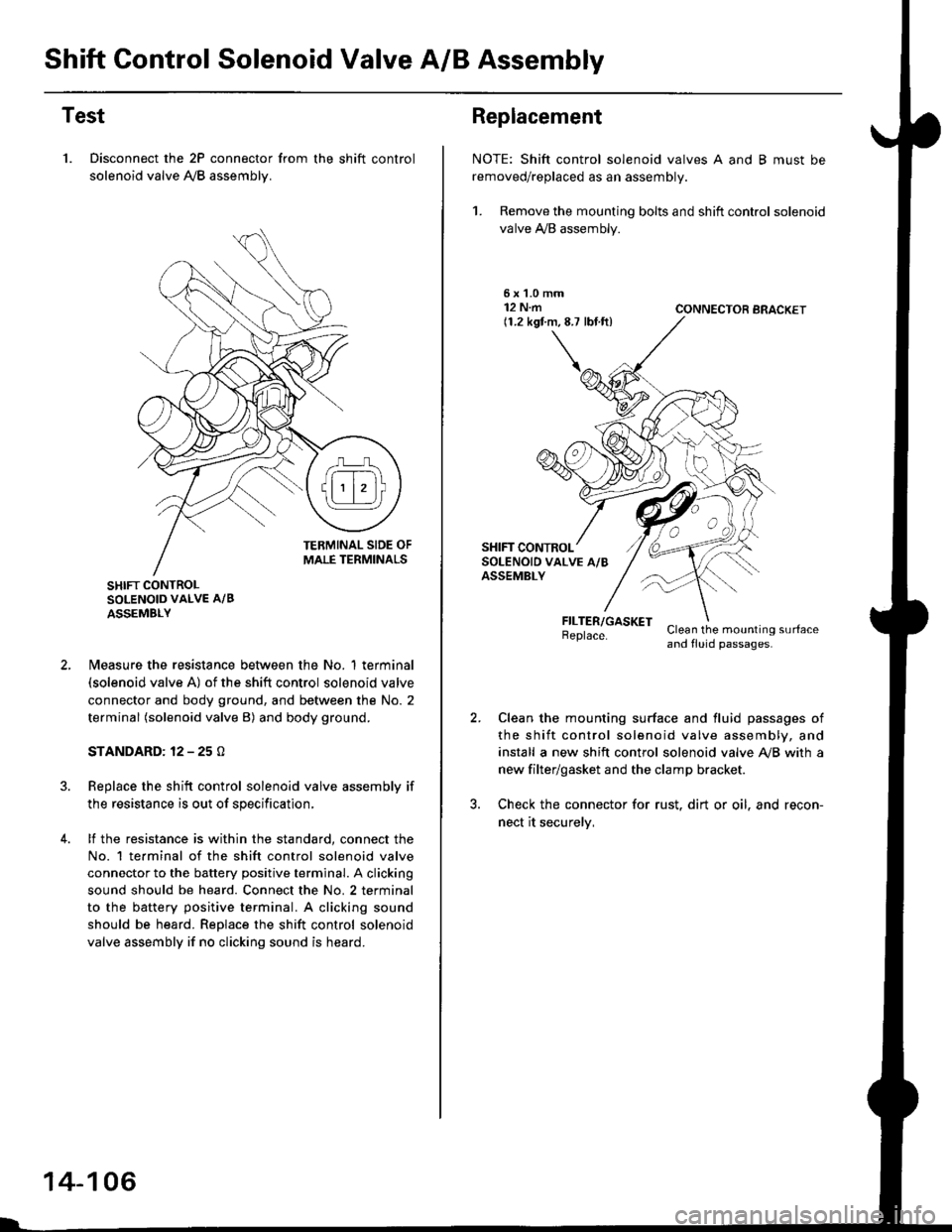
Shift Control Solenoid Valve A/B Assembly
Test
1. Disconnect the 2P connector from the shift control
solenoid valve A,/B assemblv.
SHIFT CONTROLSOLENOID VALVE A/B
ASSEMBLY
N4easure the resistance between the No. 1 terminal(solenoid valve A) of the shift control solenoid valve
connector and body ground, and between the No. 2
terminal (solenoid valve B) and body ground.
STANDARD: 12 - 25 O
Replace the shift control solenoid valve assembly if
the resistance is out of specification,
lf the resistance is within the standard, connect the
No. 1 te.minal of the shift control solenoid valve
connector to the battery positive terminal. A clicking
sound should be heard. Connect the No. 2 terminal
to the battery positive terminal. A clicking sound
should be heard. Replace the shift control solenoid
valve assembly if no clicking sound is heard.
14-106
Replacement
NOTE: Shift control solenoid valves A and B must be
removed/replaced as an assembly.
1. Remove the mounting bolts and shift control solenoid
valve A,/B assembly.
5xL0mm12 N.m(1.2 kgf.m,8.7 lbf.ft)CONNECTOR BRACKET
FILTER/GASKETBeplace.Clean the mounting surfaceand fluid passages.
Clean the mounting surface and fluid passages of
the shift control solenoid valve assembly, and
install a new shift control solenoid valve Ay'B with a
new filter/gasket and the clamp bracket.
Check the connector for rust. dirt or oil. and recon-
nect it securelv,
Page 791 of 2189

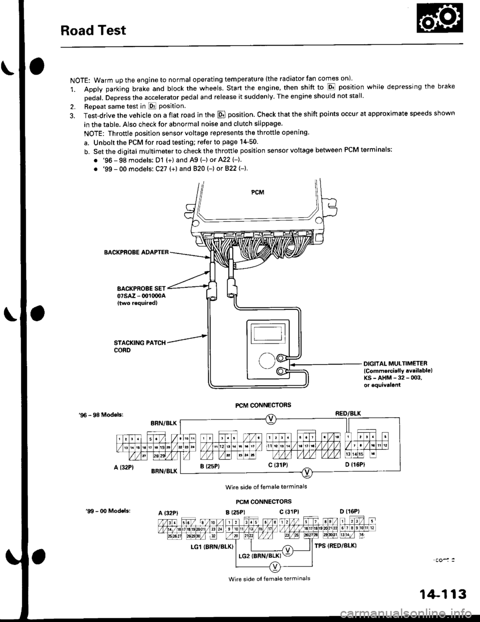
Road Test
NOTE: Warm up the engine to normal operating tem peratu re (the rad iator fan comes on )'
1. Apply parking brake and block the wheels. Start the engine, then shift to E position while depressing the brake
Dedal, Depress the accelerator pedal and release it suddenly. The engine should not stall'
2. Repeat same test in E Position.
3. Test-drive the vehicle on a flat road in the E position. Check that the shift points occur at approximate speeds shown
in the table. Also check for abnormal noise and clutch slippage.
NOTE: Throttle position sensor voltage represents the throttle opening
a. Unbolt the PCM for road testing; refer to page 14-50.
b. Setthedigital multimeter to check the th rottle position sensor voltage between PCM terminals;
. '96 - 98 models: D1 {+) and A9 (-) or 422 (-}.
. '99 - 00 models: C27 (+) andB20t-) orB22{-}.
BACKPROBE ADAPTER
BACKPROBE SET07sAz - 001oq)A{two requiredl
DIGIIAL MULTIMETERlCommercially available)KS-AHM-32-003,or equivalenl
'96 - 98 Modelsr
Wire side ol temale terminals
PCM CONNECTORS
B t25Pl c (31P)
LG1 IBRN/BLK)
I (25P1c (31P}
A t32PtD (16P)
Wire side ol female terminals
'9!t - 00 Models:
1+113