1996 HONDA CIVIC Stall test
[x] Cancel search: Stall testPage 1745 of 2189
Precautions/ Procedures
)General Precautions
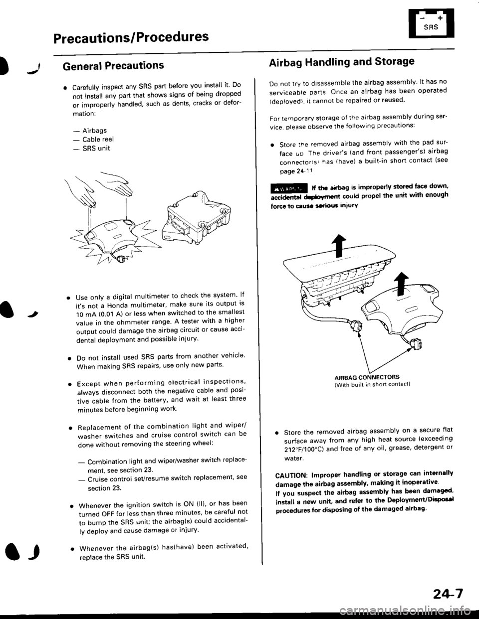
r Carefully inspect any SRS part before you install it Do
not install any part that shows signs of being dropped
or improperly handled' such as dents, cracks or defor-
mation:
- Airbags- Cable reel
- SRS unit
-
Use only a digital multimeter to check the system lf
it's not a Honda multimeter, make sure its output ls
1O mA (0.01 A) or less when switched to the smallest
value in the ohmmeter range. A tester with a higher
output could damage the airbag circuit or cause acci-
dental deployment and possible injury'
I Do not install used SRS parts from another vehicle
When making SRS repairs, use only new pans'
) Except when performing electrical inspections'
always disconnect both the negative cable and posl-
tive cable from the battery, and wait at least three
minutes before beginning work
r Replacement of the combination light and wiper/
washer switches and cruise control switch can be
done without removing the steering wheel:
- Combinalion light and wiper/washer switch replace
ment, see section 23
- Cruise control sevresume switch replacement' see
section 23.
. Whenever the ignition switch is ON {ll), or has been
turned OFF for less than three minutes' be careful not
to bump the SRS unit; the airbag(s) could accidental-
ly deploy and cause damage or injury'
. Whenever the airbag{s) has(have) been activated'
replace the SRS unit.l,
2+7
Airbag Handling and Storage
Do not try to disassemble the airbag assembly. lt has no
serviceable parts Once an airbag has been operated
(deployed). it cannot be repaired or reused'
For temporary storage of the airbag assembly during ser-
vice. olease observe the following precauttons:
. store the .emoved airbag assemblv with the pad sur-
face uo The driver's (and front passenger's) airbag
connecto''s'-as {have) a built.in short contact (see
page 2a-l 1
: | ..r r-+r-a k imninncrlv slorcd lace down,-""dd.r6t dtatltt-,tl could propel the unit whh enough
force lo c.usa 3a.ix! intury
AIRBAG CONNECTORS(With built in shon contact)
. Store the removed airbag assembly on a secure flat
surface away from any high heat source {exceeding
212"FI1OO"CJ and free of any oil' grease, detergent or
water.
CAUTION: lmproper handling or storage can intern'lJy
damage the airbag assembly, making it inoperativo
lf you suspect the airbag assembly has been dam€cd'
inslall a new unit. and relsr lo the Deployment/DisPG'l
olocedules for disposing ol the damaged airbag
Page 1747 of 2189
)
Wiring Precautions
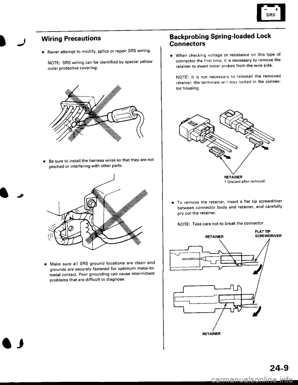
. Never attempt to modify, splice or repair SRS wiring'
NOTE: SRS wiring can be identified by special yellow
outer Protective covering.
8e sure to install the harness wires so that they are not
oinched or interfering with other parts.
t
Make sure all SRS ground locations are clean and
grounds are securely fastened for optimum metal-to-
metal contact. Poor grounding can cause intermittent
problems that are difficult to diagnose.
a,
24-9
Backprobing Spring'loaded Lock
Gonnectors
. When checking voltage or resistance on this type of
connector the flrst time, it is necessary to remove lne
retainer to insert tester probes from the wire side.
NOTE: lt is not necessary to reinstall the removed
retainer; the terminals wi I stay locked in the connec-
tor housrng.
To remove the retainer, insert a flat tip screwdriver
between connector body and retainer, and carefully
pry out the retainer.
NOTE: Take care not to break the connector.
FLAT TIPSCBEWDRIVER
RETAINER* Discard after removal.
RETAINER
Page 1812 of 2189
Cable Reel
Replacement (cont'd)
11.
NOTE:
. Before installing the steering wheel, the front
wheels should be aligned straight ahead.. Be sure to install the harness wires so that theyare not pinched or interfering with other parts.. After reassembly. confirm that the wheels arestill turned straight ahead and that the steeringwheel spoke angle is correct (road test). lf minor
spoke angle adjustment is necessary, do so onlyby adjusting the tie-rods, not by removing andrepositioning the steering wheel.
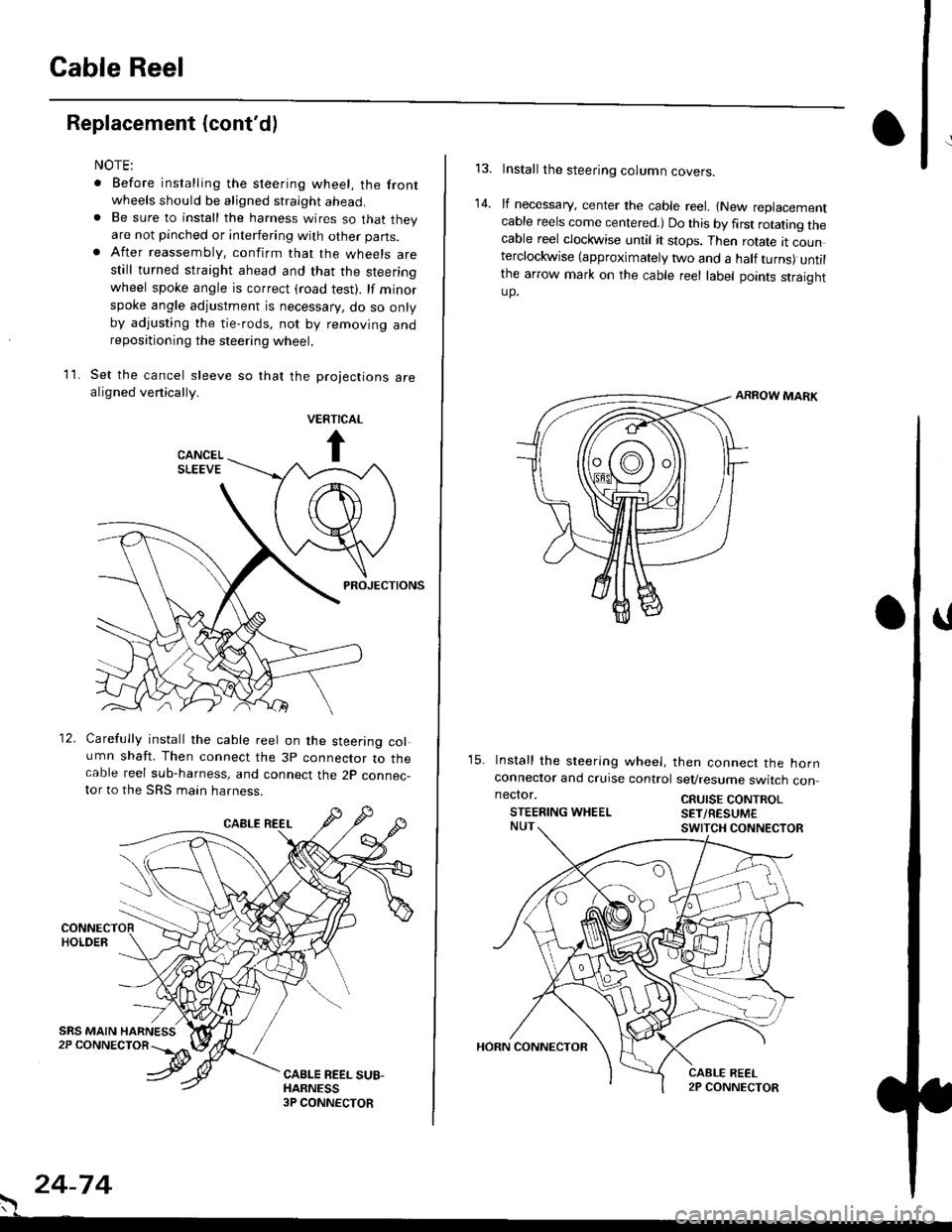
Set the cancel sleeve so that the projections arealigned venically.
PROJECTIONS
12. Carefully install the cable reel on the steering column shaft. Then connect the 3p connector to thecable reel sub-harness, and connect the 2p connec-tor to the SRS main harness.
. 24-74
Install the steering column covers.
lf necessary, center the cable reel. {New replacementcable reels come centered.) Do this by first rotating thecable reel clockwise until it stops. Then rotate tt counterclockwise (approximately two and a half turns) untilthe arrow mark on the cable reel label points straightup.
ARROW MARK
15. lnstall the sleering wheel, then connect the hornconneclor and cruise control sevresume switch con
14.
neclor.
STEERING WHEELCRUISE CONTROLSET/RESUM€
Page 1813 of 2189
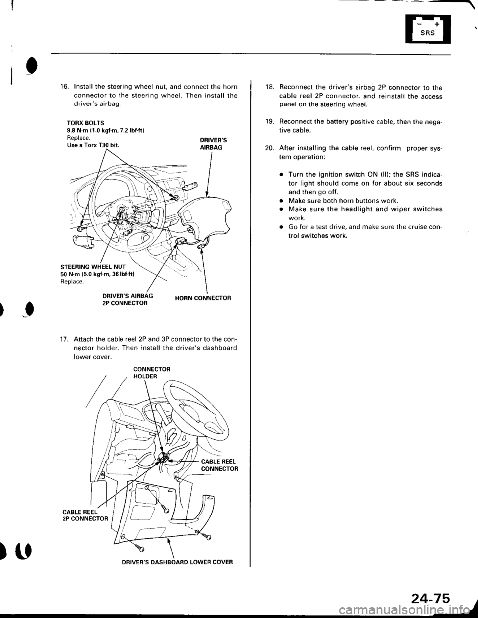
16. Install the steering wheel nut, and connect the horn
connector to the steering wheel. Then install the
driver's airbag.
TORX SOLTS9.8 N m 11.0 kgf m, 7.2 lbtftlReplace.Use a Torx T30 bit.
STEERING WHEEL NUT50 N.m 15.0 kgf.m,36lblft)Replace.
DRIVEB'SAIRBAG
DRIVER'S2P CONNECTOBHORN CONNECTOB
I
17.Attach the cable reel 2P and 3P connector to the con-
nector holder. Then install the driver's dashboard
lower cover.
)UDRIVER'S DASHBOARD LOWER COVER
24-75
18. Reconnect the driver's airbag 2P connector to the
cable reel 2P connector. and reinstall the accesspanel on the steering wheel.
19. Reconnect the battery positive cable, then the nega-
tive cable.
20. After installing the cable reel, confirm proper sys-
tem operation:
Turn the ignition switch ON (ll); the SRS indica-
tor light should come on for about six seconds
and then go off.
Make sure both horn buttons work.
Make sure the headlight and wiper switches
Go for a test drive, and make sure the cruise con
trol switches work.
a
a
Page 2030 of 2189
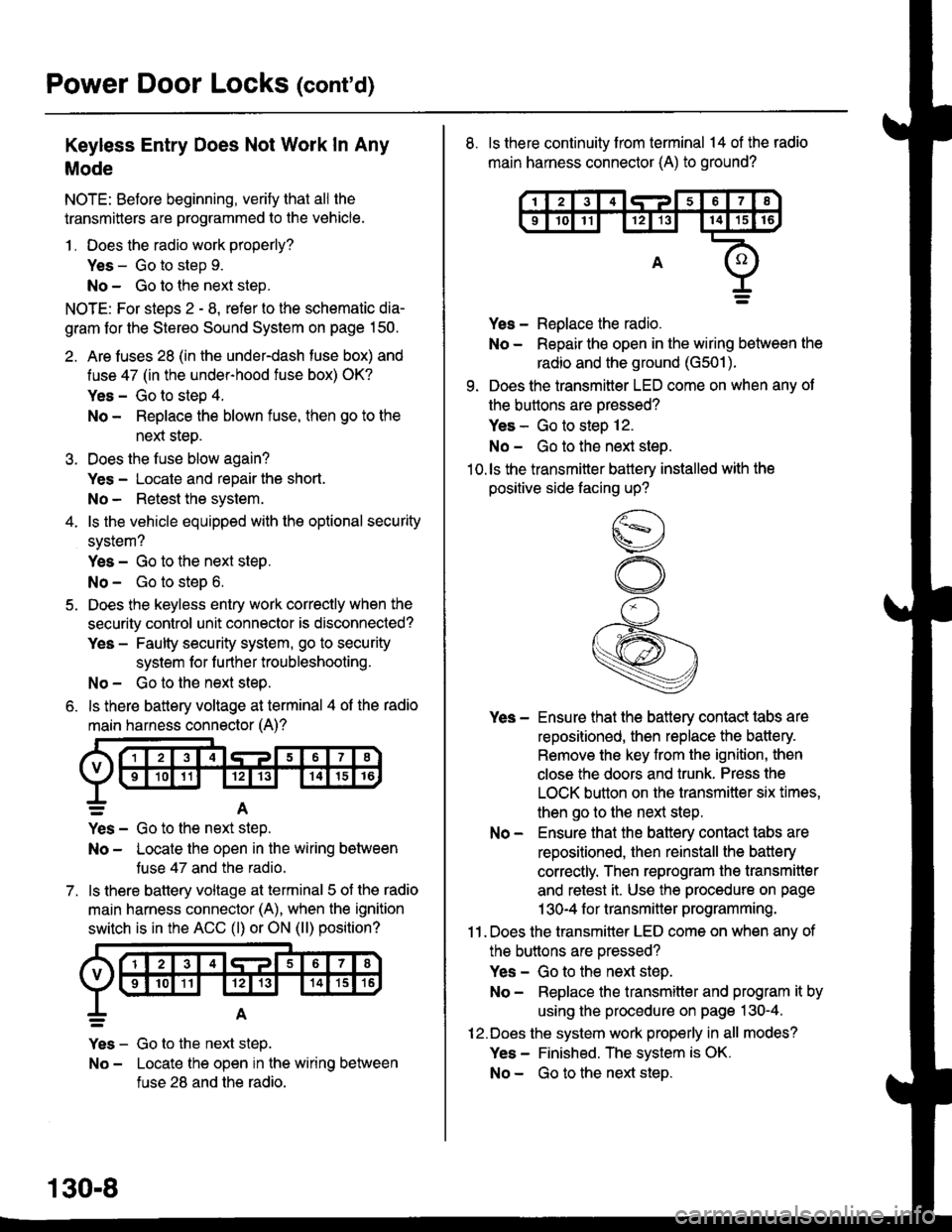
Power Door Locks (cont'd)
Keyless Entry Does Not Work In Any
Mode
NOTE: Before beginning, verify that all the
transmitters are programmed to the vehicle.
1 . Does the radio work properly?
Yes - Go to step 9.
No - Go to the neld step.
NOTE: For steos 2 - 8. refer to the schematic dia-
gram for the Stereo Sound System on page 150.
2. Are fuses 28 (in the under-dash fuse box) and
fuse 47 (in the under-hood fuse box) OK?
Yes - Go to step 4.
No - Replace the blown fuse, then go to the
nen steo.
3. Does the fuse blow again?
Yes - Locate and repair the short.
No- Retest the system.
4. ls the vehicle equipped with the optional security
system?
Yes - Go to the next steP.
No - Go to steD 6.
5. Does the keyless entry work correctly when the
security control unit connector is disconnected?
Yes - Faulty security system, go to security
system for f urther troubleshooting.
No - Go to the next step.
6. ls there battery voltage at terminal 4 of the radio
main harness connector (A)?
7.
=A
Yes - Go to the nen step.
No - Locate the open in the wiring between
tuse 47 and the radio.
ls there battery voltage at terminal 5 of the radio
main harness connector (A), when the ignition
switch is in the ACC (l) or ON (ll) position?
Yes - Go to the next step.
No - Locate the open in the wiring between
fuse 28 and the radio.
130-8
8. ls there continuity from terminal 14 of the radio
main harness connector (A) to ground?
Yes - Replace the radio.
No - Repair the open in the wiring between the
radio and the ground (G501).
9. Does the transmitter LED come on when any ot
the buttons are oressed?
Yes - Go to steo 12.
No - Go to the next steo.'10.ls the transmitter battery installed with the
positive side facing up?
Yes - Ensure that the battery contact tabs are
repositioned, then replace the battery.
Remove the key from the ignition, then
close the doors and trunk. Press the
LOCK button on the transmitter six times,
then go to the next step.
No - Ensure that the baftery contact tabs are
repositioned, then reinstall the batlery
correctly. Then reprogram the transmitter
and retest it. Use the procedure on page
1 30-4 f or transmitter programming.
11 . Does the transmitter LED come on when any of
the buttons are oressed?
Yes - Go to the next step.
No - Replace the transmitter and program it by
using the procedure on page 130-4.
12.Does the system work properly in all modes?
Yes - Finished. The system is OK.
No - Go to the next steD.
Page 2031 of 2189
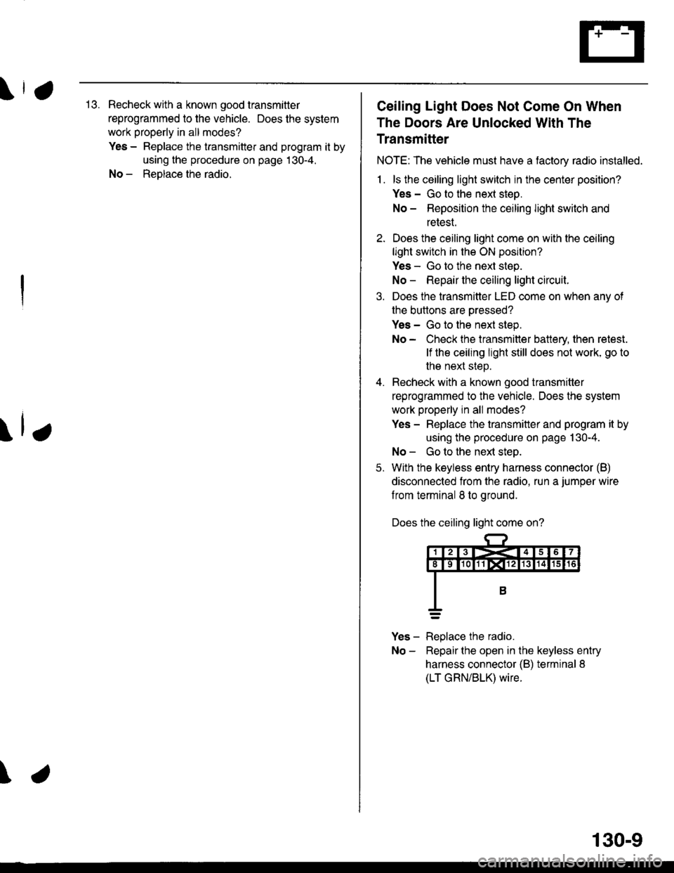
\,113. Recheck with a known good transmitler
reprogrammed to the vehicle. Does the system
work properly in all modes?
Yes - Replace the transmitter and program it by
using the procedure on page 130-4.
No - ReDlace the radio.
\lr
\
Ceiling Light Does Not Come On When
The Doors Are Unlocked With The
Transmitter
NOTE: The vehicle must have a tactory radio installed.
1 . ls the ceiling light switch in the center position?
Yes - Go to the nexl steo.
No - Reposition the ceiling light switch and
retest.
2. Does the ceiling light come on with the ceiling
light switch in the ON position?
Yes - Go to the next step.
No - Repair the ceiling light circuit.
3. Does the transmitter LED come on when anv of
the buttons are oressed?
Yes - Go to the next step.
No - Check the transmitter battery, then retest.
lf the ceiling light still does not work, go to
the next steD.
4. Recheck with a known good transmitter
reprogrammed to the vehicle. Does the system
work properly in all modes?
Yes - Replace the transmitter and program it by
using the procedure on page 130-4.
No - Go to the ne)d steo.
5. With the keyless entry harness connector (B)
disconnected from the radio. run a jumper wire
f rom terminal 8 to ground.
Does the ceiling light come on?
Yes - Replace the radio.
No - Repairthe open in the keyless entry
harness connector {B) terminal 8
(LT GRN/BLK) wire.
130-9
Page 2039 of 2189
rl,
;
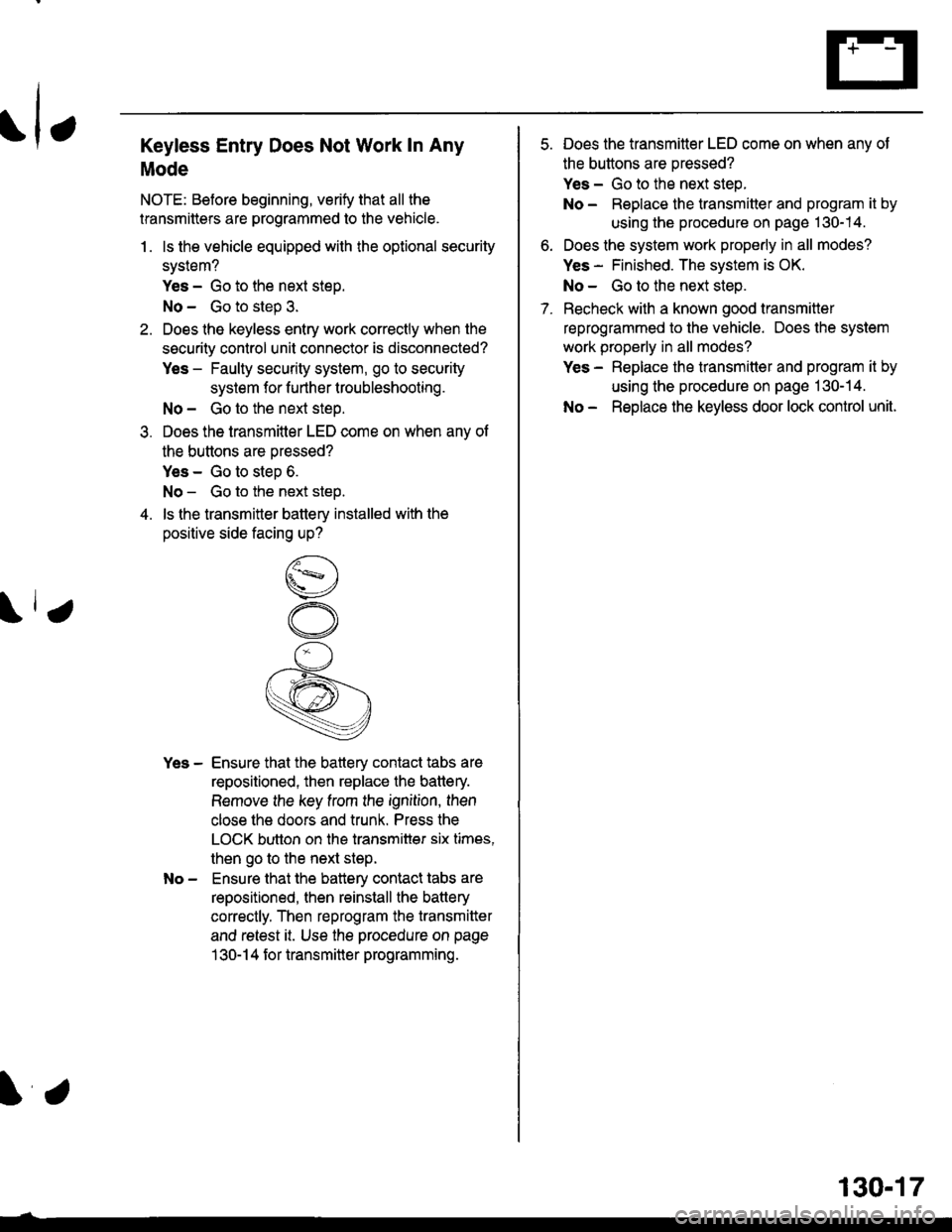
Keyless Entry Does Not Work ln Any
Mode
NOTE: Before beginning, verify that all the
transmitters are programmed to the vehicle.
1. ls the vehicle equipped with the optional security
system?
Yes - Go to the next steD.
No - Go to step 3.
2. Does lhe keyless entry work correctly when the
security control unit connector is disconnected?
Yes - Faulty security system, go to security
system for f urther lroubleshooting.
No - Go to the next steo.
3. Does the transmitter LED come on when anv of
the buttons are pressed?
Yes - Go to step 6.
No - Go to the next step.
4. ls the transmitter battery installed with the
positive side facing up?
Yes - Ensure that the battery contact tabs are
repositioned, then replace the battery.
Remove the key trom the ignition, then
close the doors and trunk. Press the
LOCK button on the transmitter six times,
then go to the next step.
No - Ensure that the battery contact tabs are
repositioned, then reinstall the battery
correctly. Then reprogram the transmitter
and retest it. Use the procedure on page
1 30-1 4 for transmitter programming.
130-17
7.
Does the transmitter LED come on when anv of
the buttons are oressed?
Yes - Go to the next steo.
No - Replace the transmitter and program it by
using the procedure on page 130-14.
Does the system work properly in all modes?
Yes - Finished. The system is OK.
No - Go to the next step.
Recheck with a known good transmitter
reprogrammed to the vehicle. Does the system
work properly in all modes?
Yes - Replace the transmitter and program it by
using the procedure on page 130-14.
No - Replace the keyless door lock control unit.