1996 HONDA CIVIC steering wheel
[x] Cancel search: steering wheelPage 1129 of 2189
?
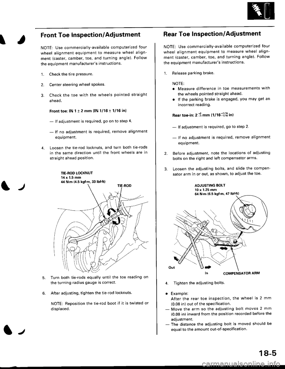
Front Toe Inspection/Adiustment
NOTE: Use commercially-available computerized four
wheel alignment equipment to measure wheel align-
ment (caster, camber, toe, and turning angle). Follow
the equipment manufacturer's instructions.
1. Check the tire pressure.
Center steering wheel spokes.
Check the toe with the wheels pointed straight
a head.
Front toe: lN 1 1 2 mm llN l/16 r 1/16 inl
- lf adjustment is required, go on to step 4.
- lf no adjustment is required, remove alignment
equrpmenr.
Loosen the tie-rod locknuts, and turn both tie-rods
in the same direction until the front wheels are in
straight ahead position.
TIE.ROD LOCKNUT'14 x 1.5 mm
4.
tJ
6.
Turn both tie-rods equally until the toe readang on
the turning radius gauge is correct.
After adjusting, tighten the tie-rod locknuts.
NOTE: Reposition the tie-rod boot if it is twisted or
displaced.
4,1 N.m {4.5 kgf.m, 33 lb{.ft)
2.
Rear Toe Inspection/Adiustment
NOTE: Use commercially-available computerjzed Iour
wheel alignment equjpment to measure wheel align-
ment (caster, camber, toe, and turning angle). Follow
the equipment manufacturer's instructions.
1. Release parking brake.
NOTE:
a Measure difference in toe measurements wlth
the wheels pointed straight ahead.
. if the parking brake is engaged, you may get an
incorrect readang,
Rear toe-in: 2 11 mm ttltollllS int
- lf adjustment is required, go to step 2.
- lf no adjustment is required, remove alignment
equipment.
Before adjustment, note the locations of adiusting
bolts on the right and left compensator arms
Loosen the adjusting bolts, and slide the compen
sator arm in or out. as shown, to adjust the toe
ADJUSTING BOLT10 x 1.25 mm
In CoMPENSAToR ARM
4. Tighten the adiusting bolts
. Example:
After the rear toe inspection, the wheel is 2 mm
(0.08 in) out of the specification.- Move the arm so the adjusfing bolt moves 2 mm
(0.08 in) inward trom the position recorded before the
adjustment.- The distance the adjusting bolt is moved should be
equal to the amount out-of-specification.
64 N.m 16.5 ksf m, 47 lbtft)
18-5
Page 1374 of 2189
Heater and Air Conditioning
Heater '.'..""" 21'1
Air Conditioning ......."'.. "' 22-1
SUPPLEMENTAL RESTRAINT SYSTEM (SRS}
The civic sRs includes a driver's airbag located in the steering wheel hub ln addition, all models (except some
models for canada) have a passenger's airbag located in the dashboard above the glove box'
Information necessary to safely service the sRS is included in this service Manual ltems marked with an asterisk (*)
on the contents page include, or are located near, sRs components. servicing, disassembling or replacing these
items will require special precautions and tools, and should therefore be done by an authorized Honda dealer'
@-";;il rendsring the SRS inoperative, which could lead to personal iniury or deaih in the svent of a sev€re
frontal collision. all SRS service work must be pertormed by an authorized Honda d€aler'
. lmploper service procedures, including incorrest removal and instsllation of the sRs, could lead to personal
iniury caused by unintentional deployment of the airbags'
o Do not bump the SRS unit. Otherwise. the system may fait in case of a collision. or the airbags may deploy
when the ignition switch is ON {ll}'
. sRs electrical wiring harncsses are id€ntified by yellow colol coding. Related components ale located in lhe
steering column, front console, dashboard, dashboald lowet panel, and in the dashboard above the glove box'
Do not use electricaltest equipment on these circuits.
Page 1509 of 2189
D
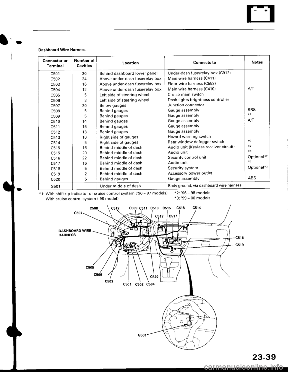
Dashboard Wire Harness
Connector ol
Terminal
Numbel of
CavitiesLocationConnects toNotes
c501
c502
c503
c504
c505
c507
c508
c509
c510
c513
c514
c515
c516
c518
c519
c520
20
24
to
12
5
3
20
5
5
14
r0
5
20
22
5
2
5
Behind dashboard lower panel
Above under-dash luse/relay box
Above under dash Iuse/relay box
Above under dash tuse/relay box
Left side of steering wheel
Left side of steering wheel
Below gauges
Behind gauges
Behind gauges
Behind gauges
Behind gauges
Behind gauges
Right side ot gauges
Right side oI gauges
Beh ind middle of dash
Behind middle of dash
Behind middle of dash
Behind middle of dash
Behind middle of dash
Behind middle of dash
Behind gauges
Under-dash {use/relay box (C912)
Main wire harness 1C411)
Floor wire harness (C553)
Main wire harness (C410)
Cruise main switch
Dash lights brightness controller
Junction connector
Gauge assembly
Gauge assembly
Gauge assembly
Gauge assembly
Gauge assembly
Hazard warning switch
Rear window defogger switch
Audio unit (Keyless receiver circuit)
Audio unit
Security control unit
Audio unit
Security system
Accessory power outlet
Gauge assembly
A"r
SRS
A,/r
Optio nal*'�
Option al*'�
ABS
G501Under middle ol dashBody ground, via dashboard wire harness
*1: With shiit-up indicator or cruise control system ('96 - 97 models)
With cruise control system ('98 model)
c509 C511 c510 c515
13 lc5l7
*2: '96 98 models*3: '99 - 00 models
c508
DASHSOARD WIREHARNESS
c501
c520
c502 c504
23-39
Page 1512 of 2189
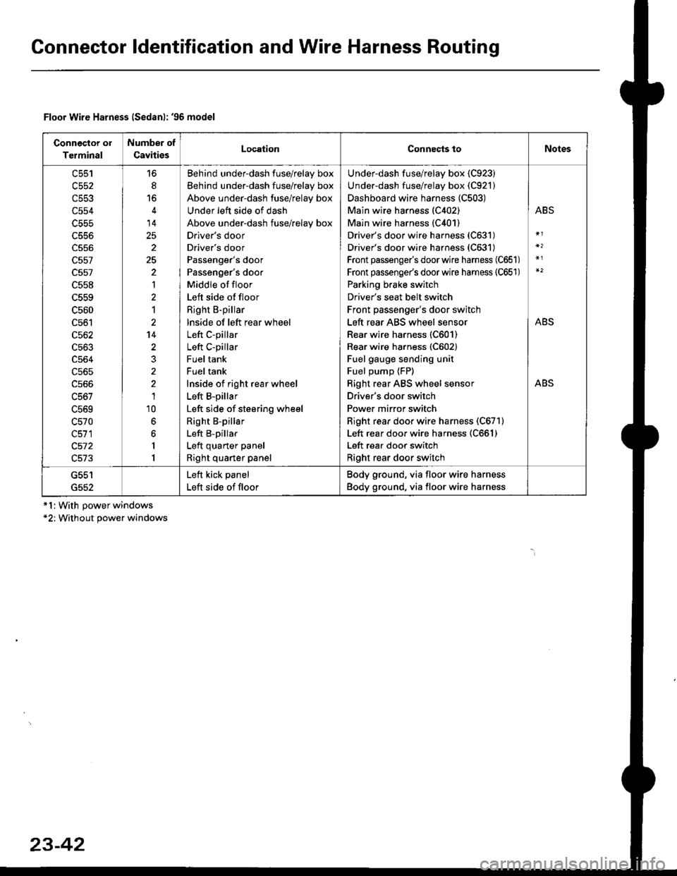
Gonnector ldentification and Wire Harness Routing
Connector ol
Terminal
Number of
CavitiesLocationConnects toNotes
c553
c554
c556
c557
c557
c558
c559
c560
c561
c562
c563
c564
c565
c566
c567
L5bY
c570
c511
c572
c513
6
14
25
2
25
'|
1
2't4
1'10
6
6
I
1
Behind underdash fuse/relay box
Behind under-dash fuse/relay box
Above under-dash fuse/relay box
Under left side of dash
Above under-dash fuse/relay box
Drlver's door
Driver's door
Passenger's door
Passenger's door
Middle of floor
Left side of floor
Right B-pillar
lnside of left rear wheel
Left C-pillar
Left C-pillar
Fuel tank
Fuel tank
Inside of right rear wheel
Left B-pillar
Left side of steering wheel
Right B-pillar
Left B-pillar
Left quarter panel
Right quarter panel
Under-dash fuse/relay box {C923)
Under-dash fuse/relay box (C921)
Dashboard wire harness (C503)
Main wire harness (C402)
Main wire harness (C401)
Driver's door wire harness (C631)
Driver's door wire harness (C631)
Front passenger's doorwire harness (C651)
Front passenge/s doorwire harness (C651)
Parking brake switch
Driver's seat belt switch
Front passenger's door switch
Left rear ABS wheel sensor
Rear wire harness (C601)
Rear wire harness (C602)
Fuel gauge sending unit
Fuel pump {FP)
Right rear ABS wheel sensor
Driver's door switch
Power mirror switch
Right rear door wire harness (C671)
Left rear door wire harness (C661)
Left rear door switch
Right rear door switch
ABS
ABS
ABS
G552
Left kick panel
Left side of floor
Body ground, via floor wire harness
Body ground, via floor wire harness
Floor Wire Harness lSedanl: '96 model
*l:With power windows*2; Without power windows
23-42
Page 1514 of 2189
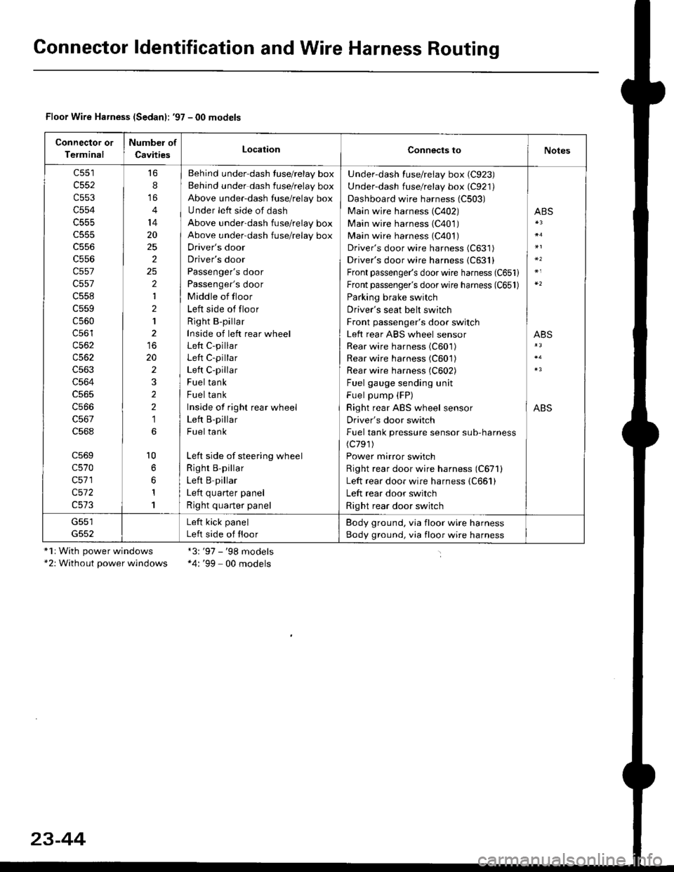
Gonnector ldentification and Wire Harness Routing
Floor Wire Harness (Sedanl: '97 - 00 models
Connector or
Terminal
Number of
CavitiesLocationConnects toNotes
c552
c553
c554
c555
c556
c557
c557
c558
c559
c560
c56'l
c562
c563
c564
c566
c568
c569
c570
c571
c572
16
8
14
20
25
2
2
1
2
1
20
2
2
2
1
l0
1
1
Behind under-dash fuse/relay box
Behind under dash fuse/relay box
Above under-dash fuse/relay box
Under left side of dash
Above under-dash fuse/relay box
Above under-dash fuse/relay box
Driver's door
Driver's door
Passenger's door
Passenger's door
Middle of floor
Left side of floor
Right B-pillar
Inside of left rear wheel
Left C-pillar
Left C-pillar
Left C-pillar
Fuel tank
Fuel tank
Inside of righr rear wheel
Left B-pillar
Fuel tank
Left side of steering wheel
Righr B,pillar
Left B pillar
I ofr ^,,.riar ^.^al
Right quarter panel
Under-dash fuse/relay box (C923)
Under-dash fuse/relay box (C921)
Dashboard wire harness (C503)
Main wire harness (C402)
Main wire harness (C401)
Main wire harness (C401)
Driver's door wire harness (C631)
Driver's door wire harness {C631}
Front passenger's door wire harness (C651)
Front passenger's door wire harness (C651)
Parking brake switch
Driver's seat belt switch
Front passenger's door switch
Left rear ABS wheel sensor
Rear wire harness (C601)
Rear wire harness (C601)
Rear wire harness (C602)
Fuel gauge sending unit
Fuel pump (FP)
Right rear ABS wheel sensor
Driver's door switch
Fuel tank pressure sensor sub-harness(c791)
Power mirror switch
Right rear door wire harness (C671)
Left rear door wire harness (C661)
Left rear door switch
Right rear door switch
ABS
ABS
ABS
G551Left kick panel
Left side of floor
Body ground, via floor wire harness
Body ground, via floor wire harness
"1r With power windows*2: Without power windows
*3:'97 - '98 models*4: '99 - 00 models
23-44
Page 1524 of 2189
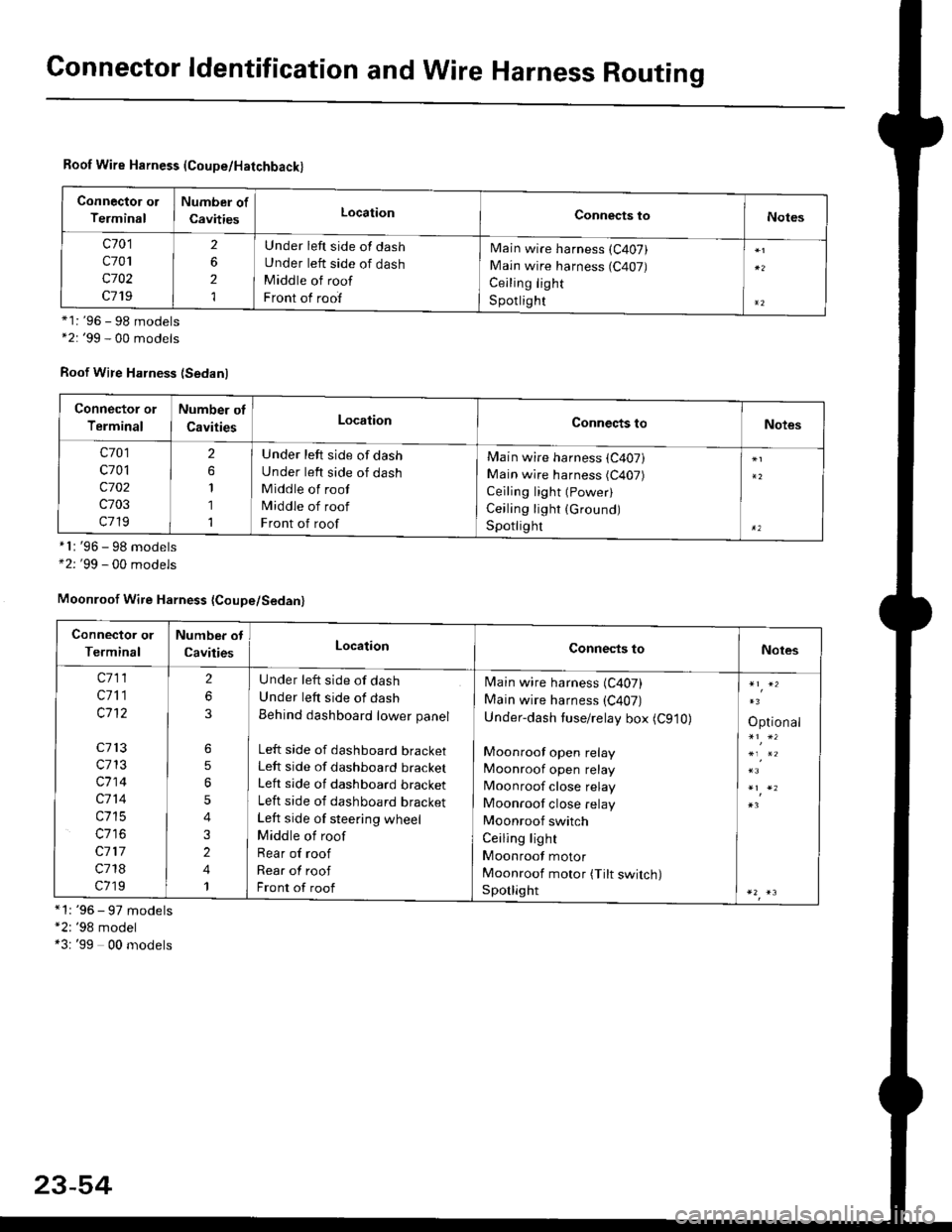
Connector ldentification and Wire Harness Routing
Roof Wire Harness (Coupe/Hatchback)
Connector ol
Terminal
Number of
CavitiesLocationConnects toNotes
c701
c701
c702
c719
2
6
2
1
Under left side of dash
Under left side of dash
Middle of roof
Front of roof
Main wire harness (C407)
Main wire harness (C407)
Ceiling light
S potlig ht*1: '96 - 98 models*2: '99 - 00 models
Roof Wire Harness (Sedanl
'96 - 98 models'99 - 00 models
*1: '96 - 97 models"2: '98 model*3: '99 00 models
*l:
+2:
Connector or
Terminal
Number of
CavitiesLocationConnects toNotes
c701
c701
c702
c703
c719
2
1
1
1
Under left side of dash
Under left side of dash
Middle of roof
Middle of roof
Front of roof
Main wire harness (C407)
Main wire harness (C407)
Ceiling light (Power)
Ceiling light (Ground)
Spotlighr
Moonroof Wire Harness {Coupe/Sedan}
Connector or
Terminal
Number ot
CavitiesLocationConnects toNotes
c711
c711
c1't2
c713
c713
c714
c714
c715
c117
c718
c719
2
6
6
5
5
4
3
2
4
1
U nder left side of dash
Under left side of dash
Behind dashboard lower panel
Left side of dashboard bracketLeft side of dashboard bracket
Left side of dashboard bracket
Left side of dashboard bracket
Left side of steering wheel
Middle of roof
Rear of roof
Rear of roof
Front of roof
Main wire harness (C407)
Main wire harness (C407)
Under-dash tuse/relay box (C910)
Moonroof open relay
Moonroof open relay
Moonroof close relay
Moonroof close relay
Moonroof switch
Ceiling light
Moonroof motor
Moonroof motor (Tilt switch)Sporlight
Optional
23-54
Page 1560 of 2189
lgnition Switch
Steering Lock Replacement
SRS components are located in this area. Review theSRS component locations. precautions, and procedures
in the SRS section (24) before performing repairs or ser-vtce.
Remove:
LMake sure you have the anti-theft code for theradio, then wire down the frequencies for theradio's preset buttons ('99 - 00 models).
Disconnect the battery negative cable.
Remove the driver's dashboard lower cover andknee bolster (see section 20).
Disconnect the 5P connector from the under-dash
fuse/relay box and the 7P connector from the mainwire harness (see previous page).
Remove the steering column covers, then removethe mounting bolts and nuts from the steering col-umn (see section l7).
Lower the steering column assembly,
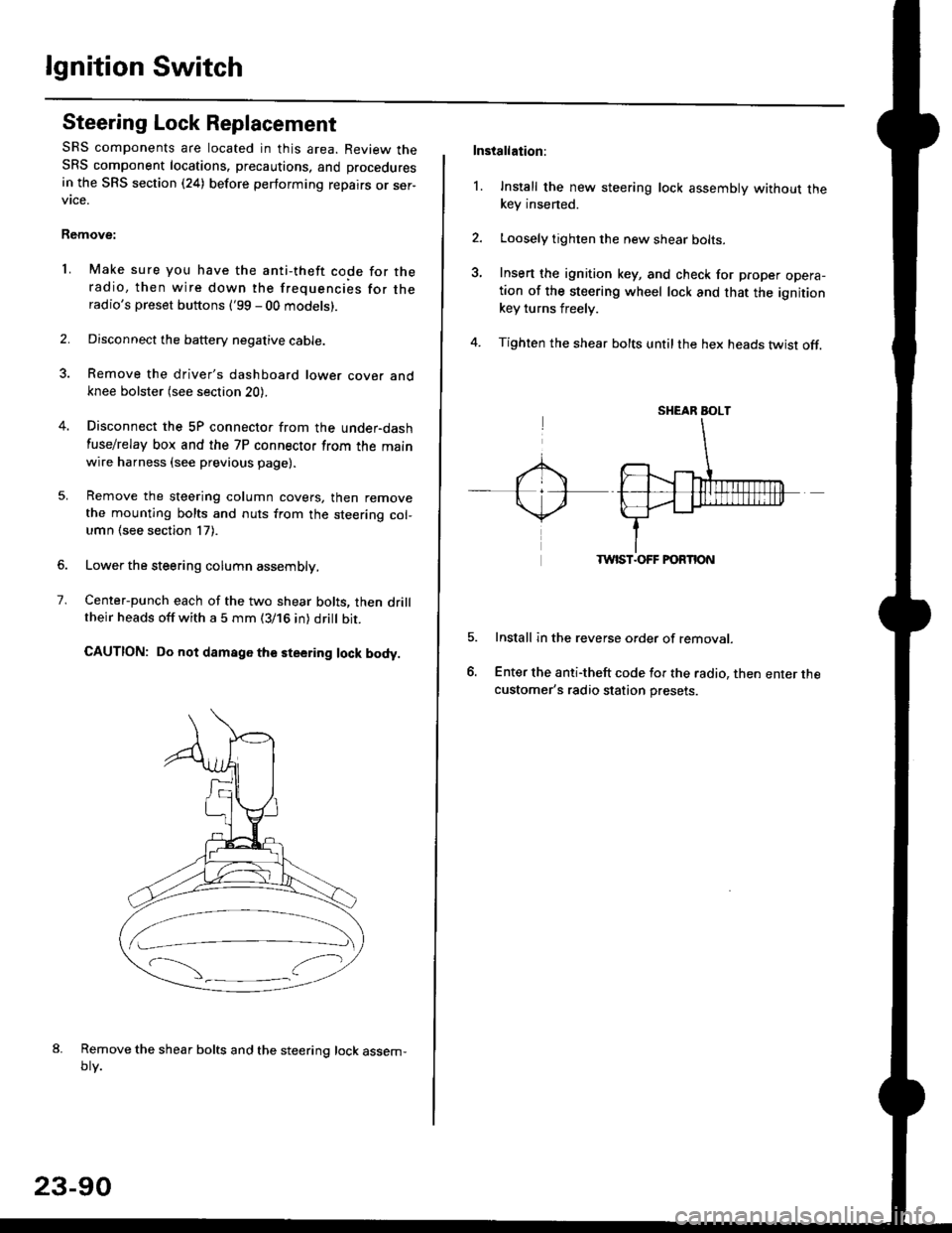
Center-punch each of the two shear bolts, then drilltheir heads off with a 5 mm (3/16 in) dritt bit.
CAUTION: Do not damago the steering lock body.
Remove the shear bolts and the steering lock assem,oty.
2.
1.
23-90
Installation:
l. Install the new steering lock assembly without thekey insened.
Loosely tighten the new shear bolts-
Insert the ignition key, and check for proper opera-tion of the steering wheel lock and that the ignitionkey turns freely.
Tighten the shear bolts untilthe hex heads twist off.
TWIST.OFF FORTION
Install in the reverse order of removar.
Enter the anti-theft code for the radio, then enter thecustomer's radio station presets.
sr{€aR SroLT
Page 1605 of 2189
JRemoval
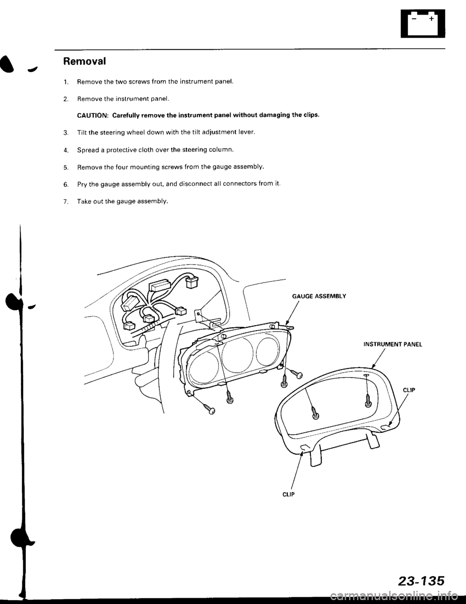
1. Remove the two screws from the instrument panel.
2. Remove the instrument panel.
CAUTION: Carefully remove the instrument panel without damaging the clips.
3. Tilt the steering wheel down with the tilt adjustment lever.
4. Spread a protective cloth over the steering column.
5. Remove the four mounting screws from the gauge assembly.
6. Pry the gauge assembly out, and disconnect all connectors from it
7- Take out the gauge assembly.
GAUGE ASSEMBLY
INSTRUMENT PANEL
23-135