1996 HONDA CIVIC steering wheel
[x] Cancel search: steering wheelPage 1090 of 2189
lnspection and Adjustment
Pump Pressure Check
Check the fluid pressure as follows to determine
whether the trouble is in the pump or gearbox.
NOTE: First check the power steering fluid level andpump belt tension.
CAUTION: Disconnect the high pr$sure hos€ with care
so as not lo spill the power sieering tluid on tha frame
and other parts.
1. Disconnect the outlet line from the Dumo outlet fit-
ting, then installthe P/S joint adaptor (pump) on the
Dumo outlet.
2. Connect the P/S joint adaptor (hose) to the power
steering pressure gauge, then connect the outlet
hose to the adaptor.
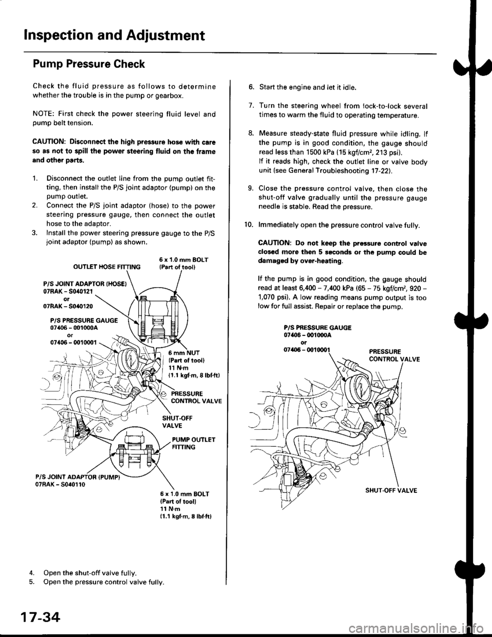
3. Install the power steering pressure gauge to the P/Sjoint adaptor (pump) as shown.
ourlEr HosE FnrNo ,t"ll lrilu"ott
P/S JOINT ADAPTOB IHOSEI07RAK - S0i10l2rol07RAK- 50{{)120
P/S PRESSURE GAUGE07406 - 001000Aor07406 - 0010001
4. Open the shut-off valve fully.
5. Open the pressure control valve fully.
17-34
(Pa.t of tooll11 N.m11.1 kgt m, 8 lbf.ftl
PRESSURECONTROL VALVE
SHUT.OFFVALVE
PUMP OUTLETFITTING
6 x 1.0 mm BOLTlPart of tool)11 N.m11.1 kgf m, 8 lbtftl
7.
Start the engine and let it idle.
Turn the steering wheel from lock-to-lock several
times to warm the fluid to operating temperature.
Measure steady-state fluid pressure while idling. If
the pump is in good condition, the gauge should
read less than 1500 kPa (15 kgf/cmr, 213 psi).
lf it reads high, check the outlet line or valve body
unit (see General Troubleshooting 17-22).
Close the pressure control valve, then close the
shut-off valve gradually until the pressure gauge
needle is stable. Read the oressure.
lmmediately open the pressure control valve fully.
GAUTION: Do not keep lhe prossure control valve
clos€d more then 5 soconds or the pump could be
damagod by over-heating.
lf the pump is in good condition, the gauge should
read at least 6,400 - 7,400 kPa (65 - 75 kgflcm,, 920 -
1,070 psi). A low reading means pump output is too
low for full assist. Repair or replace the pump,
9.
P/S PBESSURE GAUGE07{16 -@1@OA
oi
SI{UT.OFF VALVE
Page 1091 of 2189
Steering Wheel
l,/
Removal
SRS components are located in this area Review the
SRS component locations, precautions, and procedures
in the SRS section (24) before performing repairs or ser-
vice.
NOTE: Before removing the steering wheel. align the
front wheels straight ahead.
1. Remove the driver's airbag assembly from the
steering wheel (see section 24)
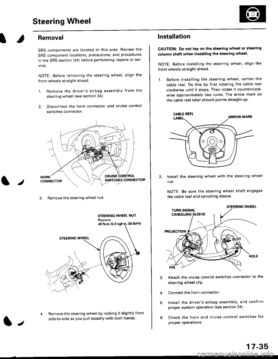
2. Disconnect the horn connector and cruise control
switches connector.
CRUISESWITCHES CONNECTOR
3. Remove the steering wheel nut
STEERING WHEEL NUT
Replace.
Remove the steering wheel by rocking it slightly from
side-to-side as you pull steadily with both hands.
ag N.m {5.0 kgt rn, 36lbfft)
1.,
17-35
lnstallation
CAUTION: Do not tap on the steering wheel or steering
column shaft when installing the stsering wheel.
NOTE: Before installing the steering wheel, align the
front wheels straight ahead.
1. Before installing the steering wheel, center the
cable reel, Do this by first rotating the cable reel
clockwise until it stops. Then rotate it counterclock-
wise approximately two turns The arrow mark on
the cable reel label should points straight up.
Install the steering wheel with the steering wheel
nut.
NOTE: Be sure the steering wheel shaft engages
the cable reel and canceling sleeve.
Attach the cruise control switches connector io the
steering wheel cliP,
Connect the horn connector.
Install the driver's airbag assembly, and confirm
proper system operation (see section 24).
Check the horn and cruise control switches for
proper operatrons.
CAELE REEL
Page 1092 of 2189
Steering Wheel
Disassembly/Reassembly
STEERING WHEEL
*@*&*W
@,
17-36
Page 1093 of 2189
Steering Column
I
Removal/lnstallation
SRS components are located in this area. Review the
SRS component locations, precautions, and proceclures
in the SRS sectron (24) before pertorming repairs or ser-
vice.
NOTE: Before removing the steering column for SRS,
remove the driver's airbag assembly and cable reel lsee
section 24).
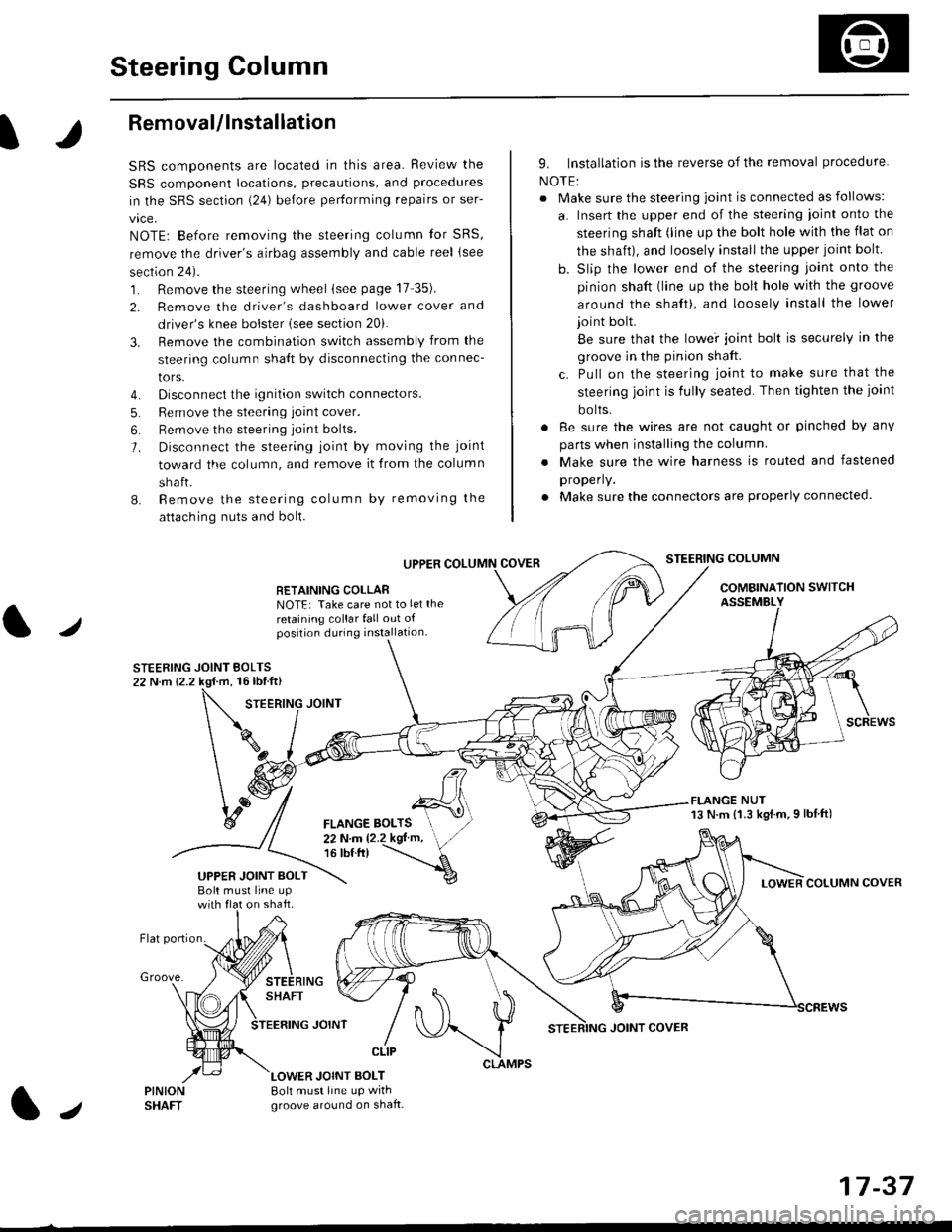
1. Remove the steering wheel (see page 17 35).
2. Remove the driver's dashboard lower cover and
driver's knee bolster (see section 20).
3. Remove the combination switch assembly from the
steering column sha{t by disconnecting the connec-
tors.
4. Disconnect the ignition switch connectors.
5. Remove the steering joint cover.
6. Bemove the steering joint bolls.
7. Disconnect the steering ioint by moving the joint
toward the column, and remove it from the column
shaft.
8. Remove the steering column by removing the
attaching nuts and bolt.
UPPER
RETAINING COLLABNOTE: Take care not to let the
retaining collar fall out ofposition during installation.
STEERING JOINT BOLTS22 N.m {2.2 kgf.m, 16lbtft}
9. Installation is the reverse of the removal procedure
NOTE:
. Make sure the steering joint is connected as follows:
a. Insert the upper end of the steering ioint onto the
steering shaft (line up the bolt hole with the flat on
the shait), and loosely install the upper joint bolt.
b. Slip the lower end of the steering joint onto the
pinion shaft (line up the bolt hole with the groove
around the shaft), and loosely install the lower
joint bolt.
Be sure that the lowei joint bolt is securely in the
groove in the pinion shaft.
c. Pull on the steering joint to make sure that the
steering joint js fully seated. Then tighten the ioint
bolts.
. 8e sure the wires are not caught or pinched by any
parts when installing the column
. Make sure the wire harness is routed and fastened
properly.
. Make sure the connectors are properly connected.
STEERING COLUMN
COMBINATION SWITCHASSEMBLY
FLANGE NUT13 N.m {1.3 kgl.m.9 lbf ft)
COLUMN COVER
FLANGE BOLTS22Nm12.2kgl'm,16 tbt.tr)
UPPER JOINT BOLTBolt musl line upon shaft.
Groove.
LOWER JOINT BOLT8oh must line up wrthgroove around on shaft.
CLIP
J
JOINT COVER
17-37
Page 1096 of 2189
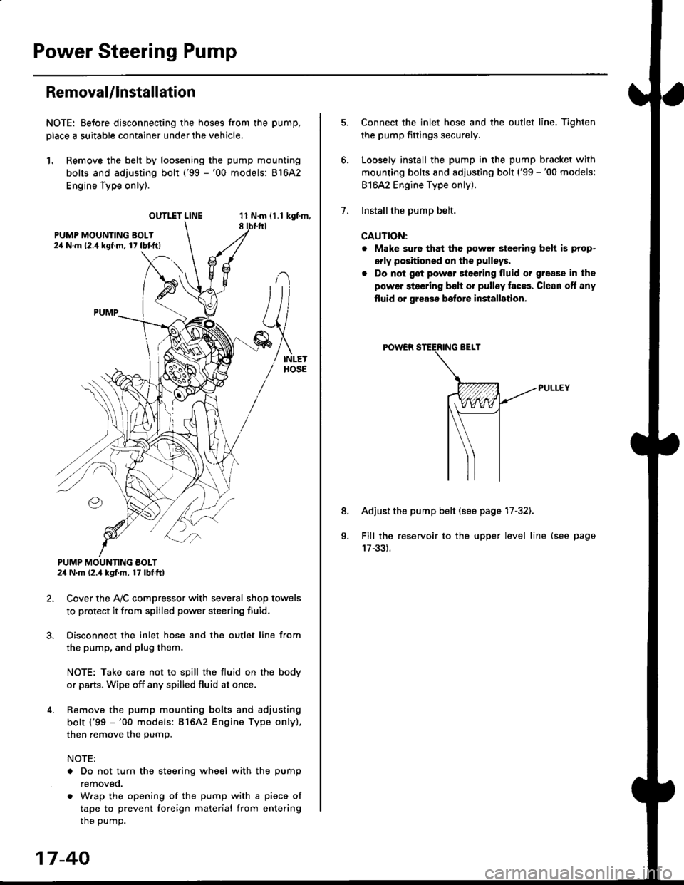
Power Steering Pump
RemovaUlnstallation
NOTE: Eefore disconnecting the hoses from the pump,
Dlace a suitable container under the vehicle.
1. Remove the belt by loosening the pump mounting
bolts and adjusting bolt ('99 -'00 models: 81642
Engine Type only).
OUTLET LINE11 N.m {1.1 kgf'm,8
L
PUMP MOUNTING BOLT24 N.m (2.4 kgl.m, 17 lbf ft)
2. Cover the Ay'C compressor with several shop towels
to protect it from spilled power steering fluid.
3. Disconnect the inlet hose and the outlet line from
the pump, and plug them.
NOTE: Take care not to spill the fluid on the body
or parts, Wipe off any spilled fluid at once.
4. Remove the pump mounting bolts and adjusting
bolt ('99 -'00 models: 816A2 Engine Type only),
then remove the pump.
NOTE:
. Do not turn the steering wheel with the pump
removeo.
. Wrap the opening of the pump with a piece of
tape to prevent foreign material from entering
the pump.
17-40
1.
8.
Connect the inlet hose and the outlet line. Tiqhten
the pump fittings securely.
Loosely install the pump in the pump bracket with
mounting bolts and adjusting bolt ('99 -'00 models:
81642 Engine Type only).
Installthe pump belt.
CAUTION:
. Make sure that the power steering belt is prop-
orly positioned on the pulleys.
. Do not get power stoering tluid or grease in the
power steering bsh or pulley faces. Clean off any
fluid or grease before installrtion.
Adjust the pump belt (see page 17-32).
Fill the reservoir to the upper level line (see page
Page 1103 of 2189
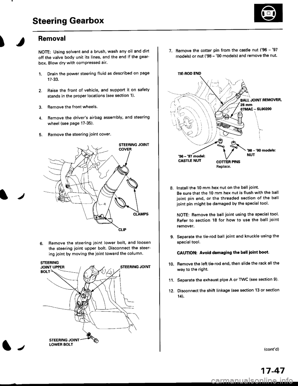
Steering Gearbox
)
Removal
NOTE: Using solvent and a brush, wash any oil and dirt
off the valve body unit its lines. and the end if the gear-
box. Blow dry with comPressed air.
1. Drain the power steering fluid as described on page
2. Raise the front of vehicle, and support it on safety
stands in the proper locations (see section 11.
3, Remove the front wheels.
4. Remove the driver's airbag assembly, and steering
wheel (see page 17-35)
5. Bemove the steering joint cover.
6. Remove the steering joint lower bolt, and loosen
the steering joint upper bolt. Disconnect the steer-
ing joint by moving the ioint toward the column
tJ
17-47
TIE.ROD END
7. Remove the cotter pin from the castle nut {'96 -'97
models) or nut ('98 - '00 modslsl and remove the nut.
BALL JOINT REMOVER.28 mm07MAC - SLqI2|X)
'98 - '00 mod.b:NUT
8.
COTTER PINSRepl6ce.
lnstall the t0 mm hex nut on the ball joint.
Be sure that the 10 mm hex nut is flush with the ball
joint pin end, or the threaded section of the ball
joint pin might be damaged by the special tool.
NOTE: Remove the ball joint using the special tool.
Refer to section 18 for how to use ths ball joint
remover.
Seoarate the tie-rod ball joint and knuckle using the
specialtool.
CAUnON: Avoid damaging tho ball ioint boot.
Remove the left tie-rod end, then slide the rack all the
way to the right.
Separate the exhaust pipe A or TWC (see section 9).
Disconnect the shift linkage (see section 13 or section
14).
(cont'd)
9.
10.
11.
12.
Page 1122 of 2189
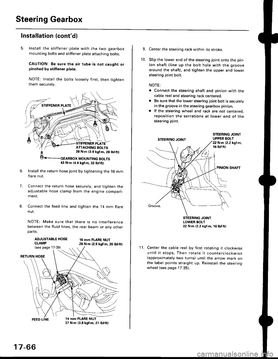
Steering Gearbox
Installation (cont'dl
5. Install the stiffener plate with the two gearbox
mounting bolts and stiffener plate aftaching bolts.
CAUTION: Be sure the air tube is not caught orpinched by stiffener plate,
NOTE: Install the bolts loosely first, then tighten
them securely.
7.
8.
6.Install the return hose joint by tightening the l6 mm
flare nut.
Connect the relurn hose securely, and tighten the
adjustable hose clamp from the engine compart-ment.
Connect the feed line and tighten the 14 mm flare
nut.
NOTE: Make sure that there is no interference
between the fluid lines, the rear beam or any otherparts.
ADJUSTABLE HOSECLAMP(see page 17-39)
16 mm FLARE NUT28 N.m {2.9 ksl.m. 20 lbf.ft)
RETURN
1a mm FLARE NUT37 N.m (3.8 kg{.m, 27 lbt.ftl
ATTACHING AOLTS38 N.m 13.9 kgf.m, 28 lbf.ftl
MOUNTING BOLTS(} N.m (4.a kgt m, 32 lbf.ftl
17-66
9.Center the steering rack within its stroke.
Slip the lower end of the steering joint onto the pin-
ion shaft (line up the bolt hole with the groove
around the shaft), and tighten the upper and lower
steering joint bolt.
NOTE:
. Connect the steering shaft and pinion with the
cable reel and steering rack centered.. Be sure that the lower steering joint bolt is securely
in the groove in the steering gearbox pinion.
. lf the steering wheel and rack are not centered,
reposition the serrations at lower end of the
steering joint.
10.
STEERING JOINTUPPER BOLT22 N.m (2.2 kgf.m,16 tbt.ftl
PINION SHAFT
Groove,
STEERING JOINTLOWER BOLT22 N.m (2.2 kgt.m, 16lbtttl
11.Center the cable reel by first rotating it clockwise
until it stops. Then rotate it counterclockwise(approximately two turns) until the arrow mark onthe label points straight up. Reinstall the steeringwheel (see page 17 35).
Page 1123 of 2189
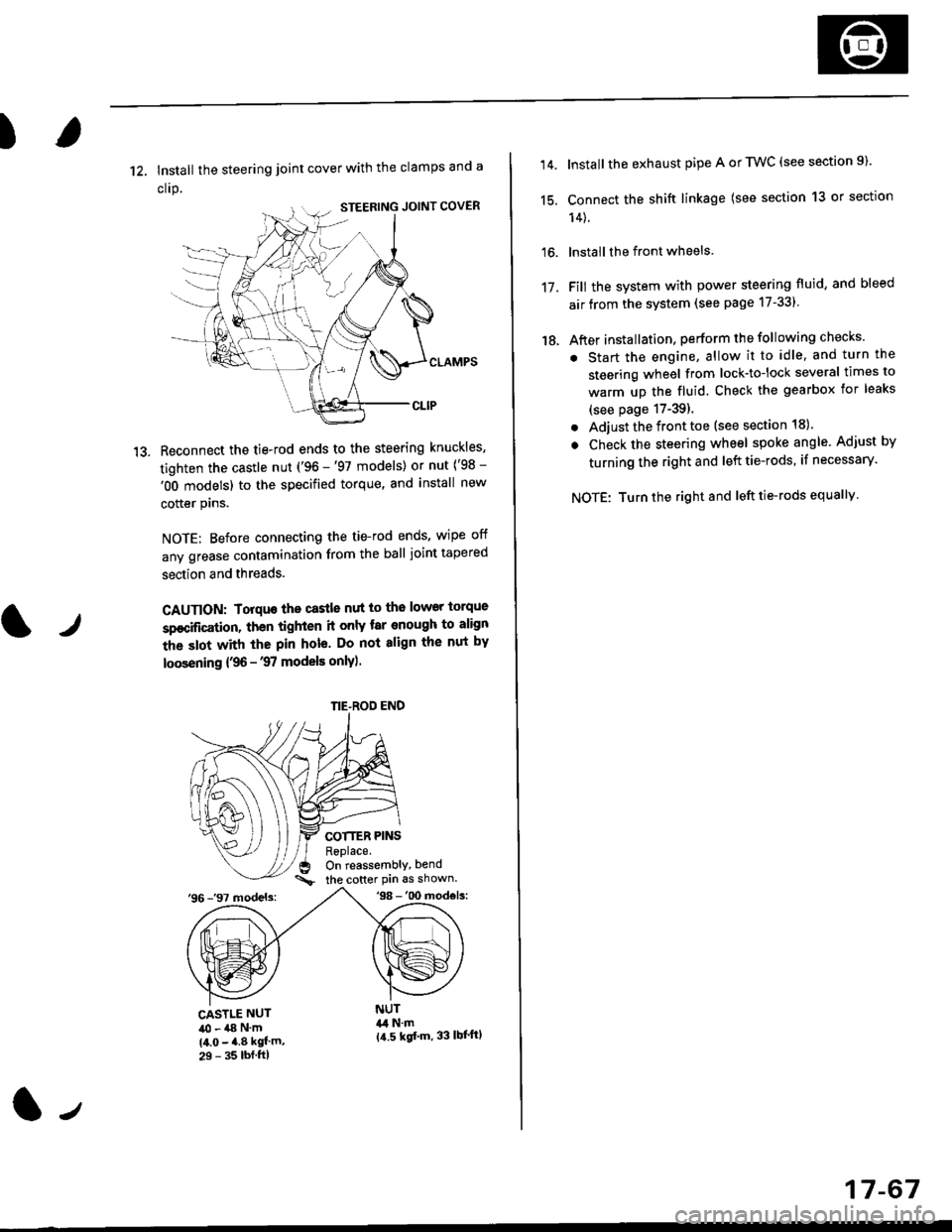
)
1?
12, Install the steering joint cover with the clamps and a
clrp.
Reconnect the tie-rod ends to the steering knuckles,
tighten the castle nut ('96 -'97 models) or nut ('98 -
'OO models) to the specified torque, and install new
cotter plns.
NOTE: Before connecting the tie-rod ends, wipe off
any grease contamination from the ball joint tapered
section and threads.
CAUTION: Torquo the castle nut to the lower torque
sp€cification, then tighten it only tar enough to align
the slot with the pin hole. Do not align the nut by
loosening {,96 -'97 models only).
COTTER PINSReplace.On reassembly, bend
the cotter Pin 6s shown.'96 -'97 models:'98 -'00 mod€ls:
tr
CASTLE NUT40 - a8 N'm(4.0 - 4.8 kgf'm,29 - 35 lbf.ftl
NUT&l N.m{a.5 kgf'm, 33 lbl'ftl
NE-ROD END
(l-,
17-67
14.
15.
16.
17.
18.
Install the exhaust pipe A or TWC (see section 9).
Connect the shift linkage (see section 13 or section
14).
lnstall the front wheels
Fill the system with power steering fluid, and bleed
air from the system (see page 17-331
After installation, perform the following checks
. Start the engine, allow it to idle, and turn the
steering wheel from lock-tolock several times to
warm up the fluid. Check the gearbox for leaks
(see page 17-39).
. Adjust the front toe (see section 18).
. Check the steering wheel spoke angle. Adjust by
turning the right and left tie-rods, if necessary.
NOTE: Turn the right and left tie-rods equallv