Page 1542 of 2189
Power Distribution
Circuit ldentification (conf dl
IM/T)
rGNrTtoN swrTcH (sT)(From pag€ 23{9)
YBLK ,VHT
t-
I
r**"'.fffr,u,r.*@**-_
lil.BLT(-^,I'/HT -|:1jl- BLT(RED
T
BLK ^/HT - $aner sol€ndd G401
STAFTERCUT RELAYCLUTCH SWITCH
BLIVREO
L-
rGNrTroN swtTcH (sT){From paoe 23{9)
f'7
IIBLK/WHT
NEUTFAL POSITIONswtTcH/ln lL/Tgeat \\posnion swldr/
BLT(RED
-BLK4rrHr
- srarrer sotsnoid
(Fus€felay lox sockol)lrflagGt€d conlrol unit
ELU VHT - PGM-F| main retay
BLUMHT _ ECI\T/PCM
lH#|1'#i,'f,5>-**l e ock connol unit(via intedocf switdr)
Key ints ocl solenoid
23-72
wHr + &3T:$111.9|'ij""'n'"
Page 1557 of 2189
Normally-opsn tYPe:
1. Check for continuity between the terminals
. There should be continuity between the No. 1 and
No. 2 terminals when power and ground are con-
nected to the No. 3 and No 4terminals.
o There should be no continuity between the No 1
and No.2 terminals when power is disconnected'
Terminal
Power iNo.3 - No,4) \
I2
Disconnected
Connectedoo
a
a
a
Power window relaY
Radiator fan relaY
Condenser fan relaY
A/C compressor clutch relaY
Starter cut relay: '98 - 00 models
Horn relay: '98 - 00 models
Five-ierminal type:
1. Check for continuitv between the terminals.
. There should be continuity betlveen the No. 1 and
No. 2 terminals when power and ground are con-
nected to the No. 3 and No 5terminals.
. There should be continuity between the No 2 and
No. 4 terminals when power is disconnected'
--1
I
II
t
Moonroof open relay: '96 - 97 models
Moonroof close relay: '96 - 97 models
(cont'd)
23-87
Terminal
Power (No. 3 - No. 5)\
4
Disconnectedo--o
Connectedo--o
Page 1563 of 2189
Starting System
Component Location Index
A/T GEAR POSITION SW|TCHTest, page 23'154Replacement, page 23-155
STARTER CUT RELAY (M/T}
Test, page 23-86, 87
oo
ool
CLUTCH INTERLOCK
swlTcH
BATTERYTest, page 23-91
STARTERTest, page 23'95Solenoid Test, Page 23 96
Replacement, Page 23-100
Performance Test, Page 23-101
23-93
Page 1565 of 2189

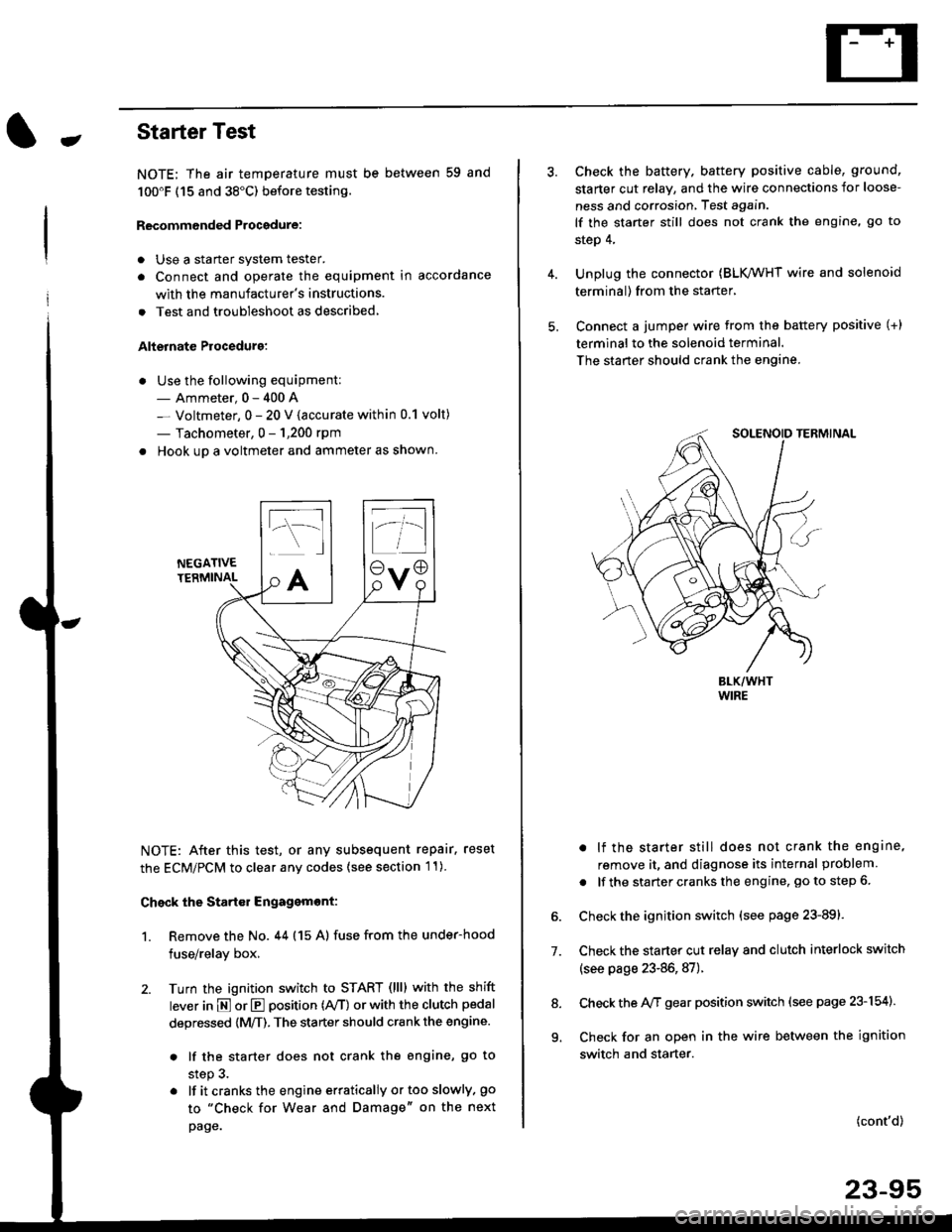
-Starter Test
NOTE; The air temoerature must be between 59 and
100'F (15 and 38"C) before testing.
Recommended Procedure:
. Use a staner system tester.
. Connect and operate the equipment in accordance
with the manufacturer's instructions.
. Test and troubleshoot as described,
Alternate Procedurg:
. Use the following equipment:- Ammeter, 0 - 400 A
- Voltmeter, 0 - 20 V (accurate within 0.1 volt)
- Tachometer, 0 - 1,200 rpm
. Hook up a voltmeter and ammeter as shown.
NEGATIVETERMINAL
NOTE: After this test, or any subsequent repair. reset
the ECM/PCM to clear any codes (see section l1)
Check the Start€r Engagemont:
1. Remove the No. 44 (15 A) fuse from the under-hood
fuse/relay box,
2. Turn the ignition switch to START (llll with the shift
lever in E or E position (rVT) or with the clutch pedal
depressed {M/T). The starter should crank the engine.
. lf the starter does not crank the engine, go to
step 3.
. lf itcranksthe engineerraticallyortooslowly, go
to "Check for Wear and Damage" on the next
page.
Check the battery. battery positive cable, ground,
starter cut relay, and the wire connections for loose-
ness and corrosion, Test again.
lf the starter still does not crank the engine, go to
step 4,
Unplug the connector (BLK,/WHT wire and solenoid
terminal) from the starter,
Connect a jumper wire from the battery positive (+)
terminal to the solenoid terminal.
The starter should crank the engine.
. lf the starter still does not crank the engine,
remove it, and diagnose its internal problem
. lf the startercranksthe engine, goto step 6.
Check the ignition switch (see page 23-891.
Check the starter cut relay and clutch interlock switch
(see page 23-86,87).
Check the A/f gear position switch (see page 23-154).
Check for an open in the wire between the ignition
switch and starter.
7.
(cont'd)
23-95
9.
Page 1713 of 2189

)
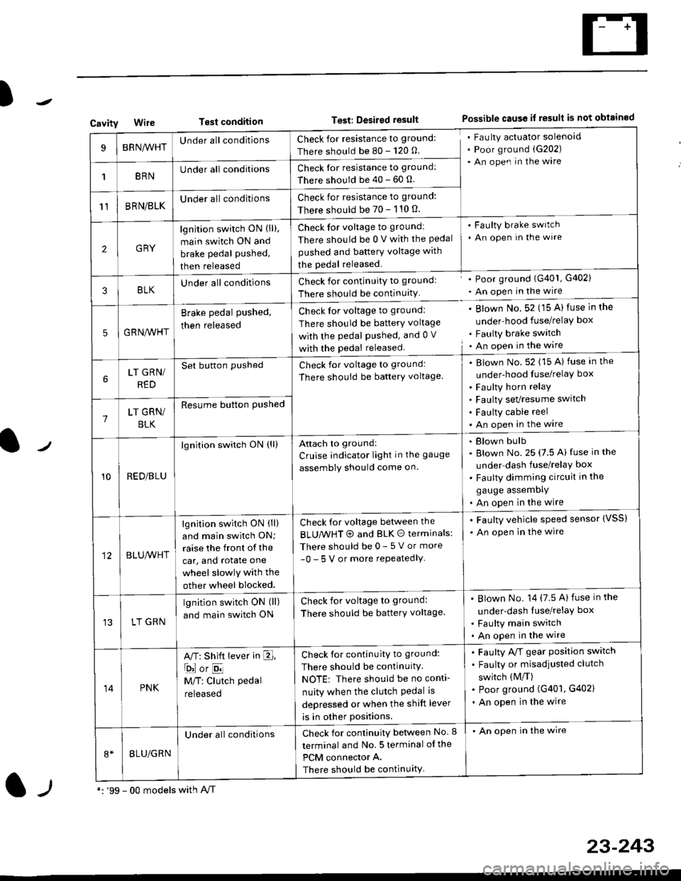
CavityWireTest conditionTest: Desired resultPossible cause if result is not obtained
BRNA/VHTUnder all conditionsCheck for resistance to ground:
There should be 80 - 120 O.
Fau lty actuator solenoid
Poor ground (G202)
An open in the wire
1BRNUnder all conditionsCheck for resistance to ground:
There should be 40 - 60 0.
11BRN/BLKUnder all conditionsCheck for resistance to ground:
There should be 70 - 110 0.
2GRY
lgn jtion switch ON (ll),
main switch ON and
brake pedal pushed,
then released
Check for voltage to ground:
There should be 0 V with the Pedal
pushed and battery voltage with
the pedal released.
'Faulty brake switch
. An open In the wlre
3BLKU nderall conditionsCheck for continuitY to groundl
There should be continuity
' Poor ground (G401, G402)
. An open in the wire
5GRNA,A/HT
Brake pedal pushed,
then released
Check for voltage to groundl
There should be batterY voltage
with the Pedal Pushed. and 0 V
with the pedal released
. Blown No. 52 (15 A) fuse in the
under-hood fuse/relaY box
. Faulty brake switch. An open in the wire
LT GRN/
RED
Set button pushedCheck for voltage to ground:
There should be batterY voltage.
Blown No. 52 (15 A) fuse in the
under-hood fuse/relaY box
Faulty horn relay
Faulty sevresume switch
Faulty cable reel
An open in the wire7LT GRN/
BLK
Resume button Pushed
10RED/BLU
lgnition switch ON (ll)Attach to ground:
Cruise indicator light in the gauge
assembly should come on.
Blown bulb
Blown No. 25 (7.5 A) fuse in the
under dash fuse/relay box
Faulty dimming circuit in the
gauge assemDly
An open in the wire
BLU,A/VHT
lgnition switch ON (ll)
and main swilch ON;
raise the front of the
car, and rotate one
wheel slowly with the
other wheel blocked.
Check for voltage between the
BLUMHT @ and BLK O terminals:
There should be 0- 5 V or more
-0- 5 V or more repeatedlY
. Faulty vehicle speed sensor {VSS)
. An open in the wire
LT GRN
lgnition switch ON (ll)
and main switch ON
Check for voltage to ground:
There should be batterY voltage.
Blown No. 14 (7.5 A)fuse in the
under-dash luse/relaY box
Faulty main switch
An open in the wire
14PNK
A,T: Shift lever in E,
ojorE
M/T: Clutch pedal
released
Check for continuity to ground:
There should be continuity.
NOTE: There should be no conti-
nuity when the clutch Pedal is
depressed or when the shift lever
is in other positions.
Faulty A/f gear position switch
Faulty or misadjusted clutch
switch (M/T)
Poor ground (G401, G402)
An open in the wire
BLU/GRN
Under all conditionsCheck for continuity between No. I
terminal and No. 5 terminal of the
PCM connector A.
There should be continuity
. An open in the wire
*: '99 - 00 models with A,/Tl-,
23-243
Page 1839 of 2189
Fuse
NumberFuse NameAmpsPage
BATTERY
Component or Circult Protected
Power distribution
lgnition switch
INTERIOR LIGHT | 7.5 | 10-10 | DLC, Ceiling light, Trunk light
FI E/M15 i(20 GX) i
i PGM-FI main relay, Fuel injection relay (GX)
Not used
POWER WINDOW| 10-10 | Power window relay
BACK UPStereo radio iuner ('9G'98 mod€ls), Audio unit ('99100
models), Heater control panel, PCM/ECM, TCM (9e'98
cvr)
HEADLIGHT
REAR DEFROSTER I
DOOR LOCK UNIT,
ROOF
i 10-12i Headlights
Not used
Rear window defogger relay
Power door lock control unit (all except '99-'00 models
with keyless), Keyless door lock control unit ('99-'00
models with keyless), Moonroof
i HORN, SrOP Lri 10-13i Horn relay, Brake switch
HAZARDHazard warning switch
OPTIONI 10-13I Security system (option)
i HEATER MOTOR Ii 10-1 i Blower motor relay
(CONDENSER FAN)
COOLING FANl1o-1
Condenser Jan relay, A'lC compressor clutch relay
Radiator tan relay
&5
Page 1840 of 2189

Ground-to-Components I ndex
f.,lONOTE: All ground wires are BLK unless otherwise noted.
GroundPageComponents or Circuit Grounded
Battery (BLKYEL)
Steering pump bracket
t+-rg ITransmission housing
l
G101
(-1)
G101
(-2)
14-2
and
14-3
ano
14-1
Powertrain or engine control module (PG1 and pG2 are BLK: LG1 and LG2 are
BRN/BLK), EGR control solenoid valve (CW, EGR valve and lift sensor (Dt6yS enginewith M,/T), Engine coolant temperature switch, pGM-Fl main relay, power steeringpressure switch (USA), Primary HO2S (D16Y5 engine with l\/,/T), Vehicle speed sensor,VTEC pressure switch (D16Y5/D16Y8 engines), CKF sensor (BRN/BLK), Transmission
control module (CYf) (Pc1 is BLK: LG1 is BRN/BLK)
Shielding betvveen the PCM or ECM and these components (all have BRN/BLK wires):
CKF sensor, TDC/CKP/CYP sensor. Primary and secondary heated oxygen sensors.
Knock sensor (CWDl6YB engine), Mainshaft speed sensor (AiT except CVT),
I Countershaft speed sensor (A/T except CVf)
Shielding between the TCM and these components (CVT) (all have BRN/BLK wires):
Drive pulley speed sensor, Driven pulley speed sensor, Secondary gear shaft
speed sensor
Powertrain or engine control module (PG1 and pG2 are BLK; LG1 and LGz are
BRN/BLK), EGR control solenoid valve (D16Y5 engine), EGR valve (Dt685), Engine
coolant temperature switch, Fuel pressure regulator shut-off solenoid valve (D1685),
PGM-FI main relay, Power steering pressure switch (USA), Vehicle speed sensor, VTECpressure switch (All except D16Y7 engine), CKF sensor (A
except 81642) (BRN/BLK)
Shielding between the PCM or ECM and these components (all have BRN/BLK wires):
CKF sensor, TDC/CKP/CYP sensor, Primary and secondary heated oxygen sensors,
Knock sensor (All except D16Y7 engine), i/ainshaft speed sensor (Arf except CW),
Countershaft speed sensor (A,/T except CVf), Drive pulley speed sensor (CW), Drivenpulley speed sensor (CVT), Secondary gear shaft speed sensor (CVf)
I Badiator fan motor, Right front parking/turn signat tight, Right headtight
G20214-4I Cruise control actuator, Left front parking/turn signal lights, Left headlight, Rear window
I washer motor, Windshield washer motor, Washer fluid level switch (,99-'00 Canada)
G401| +-o
and
14-7
Accessory power socket, Brake fluid level switch, Clutch interlock switch (M/T), Clutchswitch (lillT with cruise/D16Y5 engine with MfD, Combination wiper switch (Z wires),
Cruise control main switch, Cruise control unit, Dash lights brightness controller, Data
link connector, Daytime running lights control unit (Canada), Gauge assembly, Horn('96-'97 models), Integrated control unit, Interlock control unit (ArI), Keyless door lock
control unit ('99-'00 models with keyless), Moonroof close and open relays, Moonroof
switch, Park pin switch (A/r), Power window relay, Rear window defogger relay, Rear
window defogger switch ('96-'98 models), Steering lock, Stereo radio tuner (,96-,98
USA: LX, EX, and HX), Turn signal/hazard relay, Windshield wiper motor.....plus
everything grounded through G402
6-6
Page 1851 of 2189

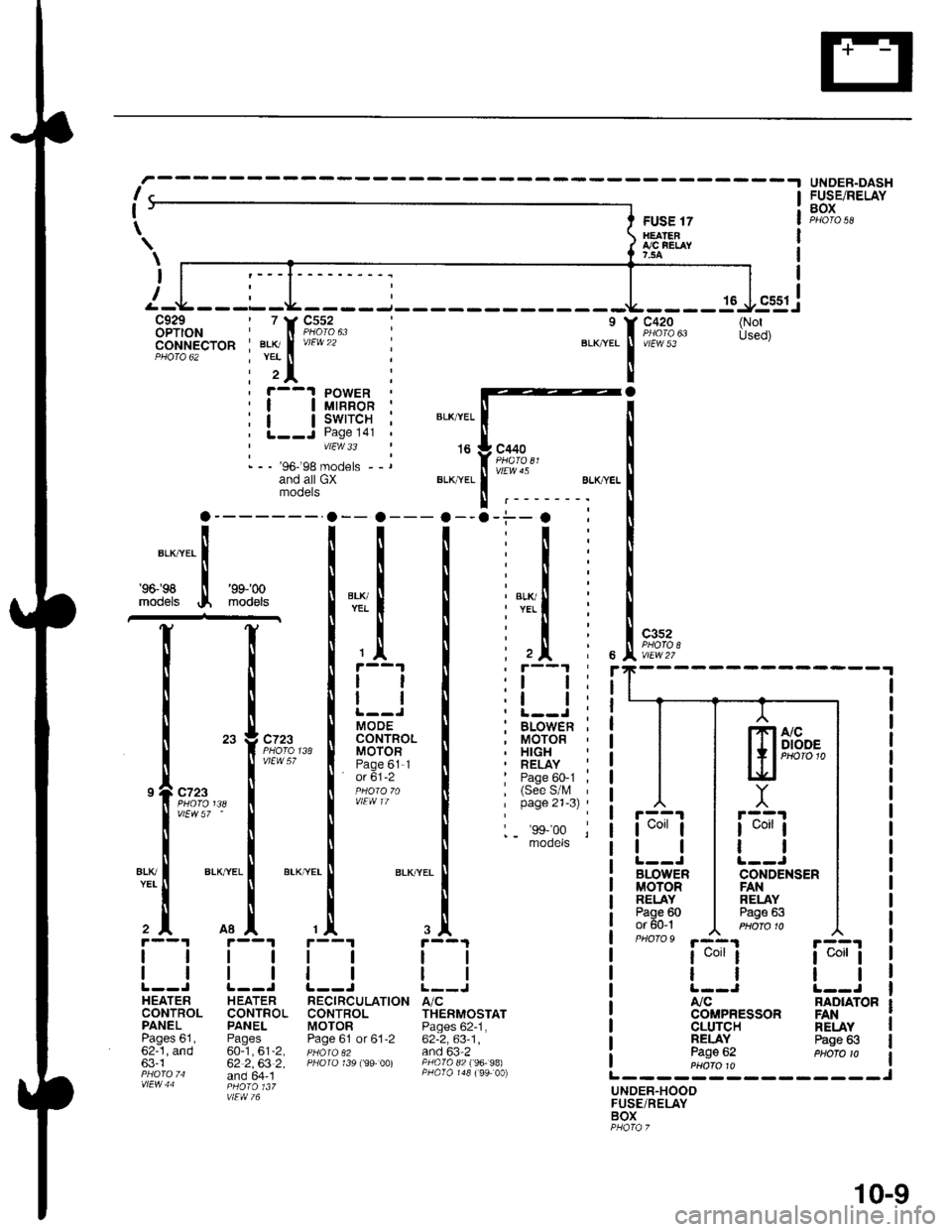
I
I
-- a---
i
i
T
iTl Ill
Irl
ll
tl
MOOECONTROLMOTORPage 61-1' o( 61-2
a
r--1 PowER| | utnnon ;| | swrrcH ;L--J Page l4l 'vtEw 33
- - - '96-'98 models --rand all GXmooers
FUSE 17H€ATENI,/C FEI,AY7,5A
16
c420
vtEw 53
c3s2
r::'l
I uorr I
tl
BLOWERMOTORRELAYPage 60or 60-1PHO|O9 '.a-4.1
I uorr I
tl
A,/C
CLUTCHNELAYPage 62
UNOER-DASHFUSE/RELAYBOX
ia;ij
tl
NAD|ATOR
\
\
I
(NotUsed)
BLK,YEL
't6
BLI(YEL
c440
vlEw 45
BLK/ryEL
'96198
models
'9$'00
mod€ls
I
c?23
vtEw 57 '
ALKTYEL
c723
vlEW 57
atK
2^
1l
ll
HEATERCONTROLPANELPages 61,62-1, and63-1
H EATERCONTROLPANEL
60-1,61-2,62 2,63 2,and 64- 1
TION A/CTHERMOSTATPages 62-1,62-2,63-1,and 63 2PAO|O 82 f96- 98)
NELAYPage 63
UNDER.HOODFUSE/RELAYBOX
ssgj
lTlA/cI I I DIODE
l+,PHoro1t.lEf
Y
r::'r
I uorr I
ll
CONDENSENFANRELAYPage 63
COMPRESSON FAN
-.i--. :
:t:
:l:
:l:
: l,T.il i
:l:
: ,Jl i, r--'t '
:l l:,t t:. L-.J ;; BLOWEn ,, MOTOR. HIGH' RELAY :: Page 60-1 ,, (See S/l\, 'I page 21-3) '
1_ 'ss,'oo lmooets
r--1
tl
ll
RECIRCULATI(CONTROLMOTORPage 61 or 61,2
10-9