1996 HONDA CIVIC ac clutch relay
[x] Cancel search: ac clutch relayPage 474 of 2189
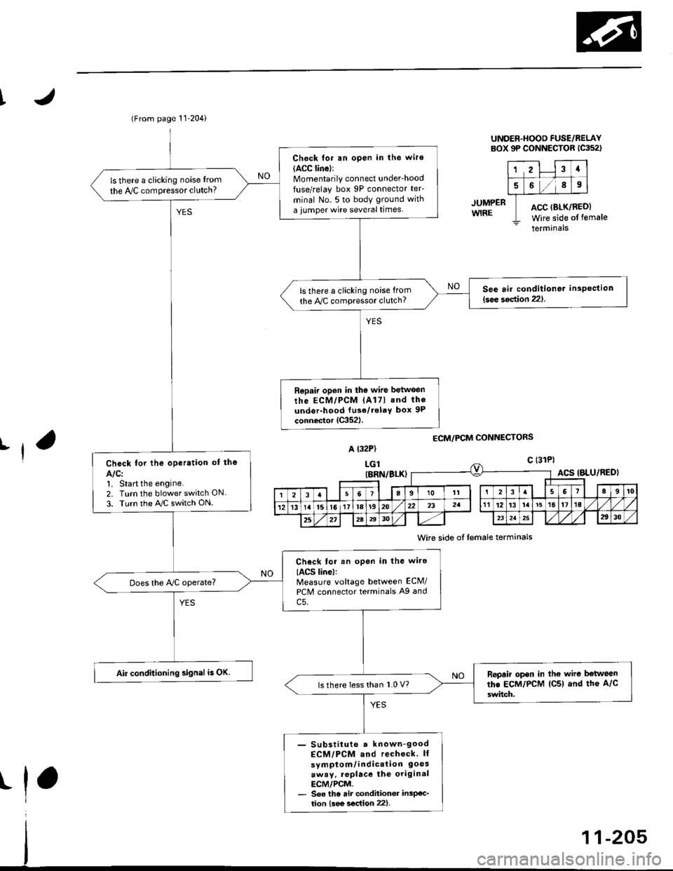
(From page 11-204)
Check for an open in the wir€(ACC linel:Momentarily connect underhood
fuse/relay box 9P connector teF
minal No. 5 to body ground with
a iumper wire several times.
ls there a clicking noise from
the IVC compressor clutch?
See air conditionor inspection(see 3oction 221.ls there a clicking noise from
the Py'C compressor clutch?
Repair open in the wire between
rhe ECM/PCM lAl7l and th6
under-hood fu3e/rolaY box 9P
connector lC352l.
Check for the oPeration of the
Alcl1. Start the engine.2. Turn the blower switch ON
3. Turn the AJC switch ON.
Chock tor an open in the wire
IACS linel:Measure voltage between ECM/
PCM connector terminals A9 and
c5.
Does the Ay'C operate?
Air conditioning signal is OK.Repair open in the wire b€tweenthe EcM/PcM lC5) and the A/c
3witch.ls there less than 1.0 V?
- Substiiute a known-goodECM/PCM and recheck ll
symptom/indication 9oesaway, .oplace the originalECM/PCM.- See the air condhioner insP€c_tion {see s€c{ion 22).
UNDER.HOOD FUSE/BELAYBOX 9P CONNECTOR 1C352)
12Ia
589
ACC (BLK/RI
Wire side ofACC (BLK/REDI
Wire side of female
terminals
JUMPERWIRE
ECM/PCM CONNECTORSrfA t32P)
LGlc {31Pl
t
(BRN/BLK)ACS IBLU/RED)
I23a9101t3I89t0
121315l611la1920232att12't3la't5t617ta
25272A2930232a2930
Wire side of lemale terminals
Page 476 of 2189

I
JUMP€RWIRE
UNDER-HOOO FUSE/RELAYsox 9P coNNEcroR lca52l
123a
5689
ACC (8LK/REDI
Wire side ofterminals
ECM/PCM CONNECTORS
A (32P1
female
Wire side of {emale terminals
(From page 11-206)
Check for an open in the wite
IACC lino):Momentarily connect under_hood
luse/relay box 9P connector teF
minal No. 5 to body ground with
a jumper wire several times.
ls there a clicking noise from
the Iy'C compressor clutch?
S6e air conditioner insPoction
l3oa section 221ls there a clicking noise lrom
the ly'C compressor clutch?
Ropair open in tho wilo betwg€n
the ECM/PCM lA17) and the A/C
clutch rolay.
Chock for the oporation of lho
AIC:1, Start the engine.
2. Turn the blower switch ON
3. Turn the ray'C switch ON.
Check lor an open in the wiro(ACS lino):Measure voltage between ECM/
PCM connector terminals A27
and 820.
Does the Iy'C operate?
Air conditioning signal is OK.Repair op6n in the wiro bctwoon
lhe ECM/PCM lA27l and tho A/C
3witch.ls voltage lessthan 1.0 V?
- Sub6iitut€ r known€ood ECtt /PCM and rccheck. ll sYmP-
tom/indication 9oe3.waY,replaca the original ECM/PCM- See the ai. condhionGr in3p€c-tion lsee soc{ion 221.
11-207
Page 507 of 2189
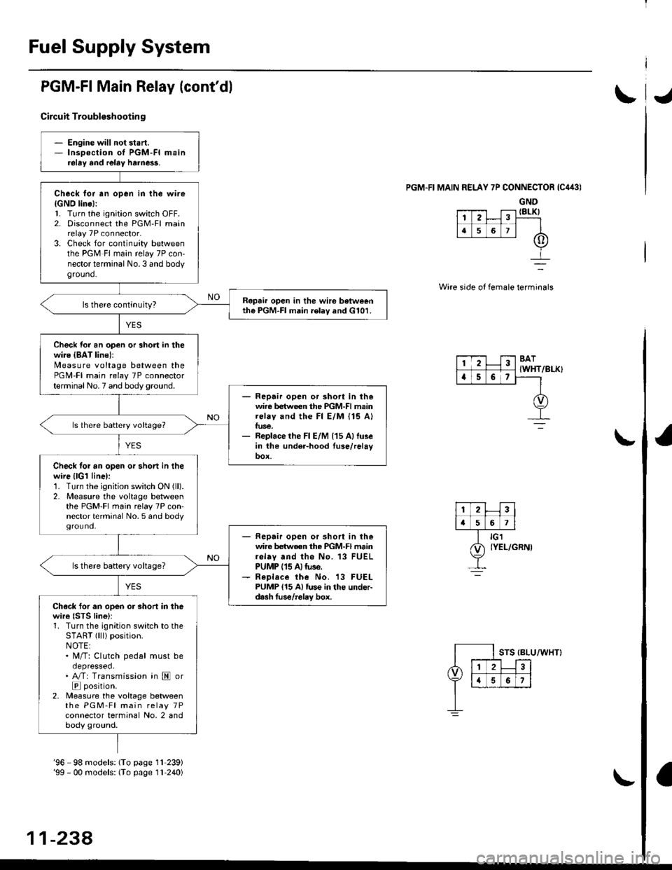
Fuel Supply System
PGM-FI Main Relay (cont'dl
Circuit Troubleshootin g
PGM.FI MAIN RELAY 7P CONNECTOR {C443)
GND{8LK)
Wire side of female terminals
/BLK}
- Engine will not start.- lnsoection of PGM-FI mainrelay and relay harne$.
Check for an open in the wire{GNO line}:l. Turn the ignition switch OFF.2. Disconnect the PGM-Fl mainrelay 7P connector.3. Check for continuity betweenthe PGM Fl main relay 7P con-nector terminal No.3 and bodyground.
Ropai. open in the wir€ betweenthe PGM-FI main .elav and G101.
Check for an open or short in thewire {BAT lin€}:N4easure voltage between thePGM-FI main relay 7P connectorterminal No. 7 and body ground.- Repair open or sho.t in thewire between the PGM-FI mainrelay and the Fl E/M {15 A}fus€.- Replace the Fl E/M (15 Allu3ein the under-hood fuse/relayoox.
ls lhere battery voltage?
Check tor an open or short in thewire {lGl line):1. Turn the ignition switch ON (ll).
2. Measure the voltage betweenthe PGM-Fl main relay 7P con'nector terminal No. 5 and bodyground.- Repair open or short in thewire betwoen the PGM-FI mainrelav and the No. 13 FUELPUMP (15 A)tuse.- R€place the No. 13 FUELPUMP {15 A} tus€ in the under-d.sh fus€/relay box.
ls there battery voltage?
Ch.ck for an open or short in thewire {STS lino}r1. Turn the ignition switch to theSTART (lll) position.NOTE:. M/T: Clutch pedal must beoepresseo.. A/T: Transmission in E or
E position.2, Measure the voltage betweenthe PGM-Fl main relay 7Pconnector terminal No, 2 andbody ground.
12
[,a567
123BAT
{WHTa56,
'96 98 models: (To page 1l 239)'99 - 00 models: (To page I l-240)
11-238,
Page 753 of 2189

Troubleshooting Flowchart - Shift Control System
NOTE: Record all freeze data before vou troubleshoot.
Possible Cause
Faulty shift control system
. OBD ll Scan Tool indicates CodeP0730.. Sell-diagnosis E indicator
light indicates Code ill.
Check tor Another CoderCheck whether the OBD ll scantool or the E, indicator lightindicate another code.
Perlorm ths TroubleshoolingFlowch.rt for the indic.t.dCode(sl. Recheck tor code m730
l4'l I atter troubleshooting.
Does the oBD ll scan tool orthe E indicato'. tight indicate another code?
Test lst, 2nd, 3rd and 4th Clutch
Pressure:Measure the 1st, 2nd, 3rd and 4th
clutch pressure (see page 14119
thru 14-121).
Ropair the hydrlulic systom !snecessary {see page 14-1 19 and11-1211.
ls each clutch pressure within
the service limit?
Replace Shift Control Solenoidvalve Assembly, Linear SolenoidAssambly and Rechock:1. Replace the shift controlsolenoid valve A'/B assembly(see page 14-106).2. Replace the linear solenoidassembly lsee page 14 108).3. Turn the ignition switch OFFand reset the PCM memory byremoving the EACK UP (7.5 A)tuse in the under hood fuse/relay box for more than l0
seconds,4. Drive the vehicle at over 12mph (20 km/h) in 1st, 2nd,3rd
and 4th gear for more than 30seconds at P1 position.
5. Recheck tor code P0730 (41).
Does the OBD ll scan tool orthe Ed indicator tight indi
cate code P0730 {41)?
The swt6m is OK et this time.
NOTE: Do not continue with this troubleshooting until the causes ot any
other DTCS have been corrected.
Page 778 of 2189
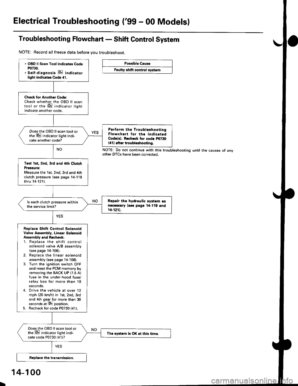
Electrical Troubleshooting ('99 - 00 Modelsl
Troubleshooting Flowchart - Shift Control System
NOTE: Record allfreeze data before you troubleshoot.
Po33ibl. Crus6
Frulty 3hift control ryrtom
. OBD ll Scan Tool indicrtd Codem730.. Self-dirgnosis E indicatorlight indicst€. Codo 41.
Check for Anoth€. Code:Check whether the OBD ll scantool or the E indicator lightindicate another code.
Prrf orm tho Troublc!hootingFlowch.rt for th. indicrt.dCod.l3l. R.ch.ck tor cod. m730141| .tt r troubldhootlng.
Doesthe OBD llscan tool orthe E indicator light indi-cate another code?
Test 13t, 2nd, 3rd .nd 4th ClutchPrglture:Measure the 1st, 2nd,3rd and 4thclutch pressure (see page 14-119thru 14 121).
R.prir tho hydrlulic ayrtam aan.c.3t..y lr.o p!9. lil-119 rnd1+1211.
ls each clutch pressure withinthe service limit?
Roplace Shift Control SolenoidValve Asembly. Linoar Sol.noidAssembly .nd Recheck:1. Replace the shift controlsolenoid valve A/B assembly(see page 14-106).2. Replace the linear solenoidassembly {see page 14-108}.3. Turn the ignition switch OFFand reset the PCM memory byremoving the BACK UP (7.5 A)fuse in the under-hood fuse/relay box for more than 10seconds,4. Drive the vehicle at over 12mph (20 kn/h) in 1st, 2nd, 3rdand 4th gear lo. more than 30seconds at lPll position.5. Recheck for code P0730 (41).
Doesthe OBD Ilscan tool orthe E ;ndicator light indi-cate code P0730 (41)?Th. sFtcm b OK .t this time.
NOTE: Do not continue with this lroubleshooting until the causes ot anyother OTCS have beon corrected.
I
14-100
Page 909 of 2189
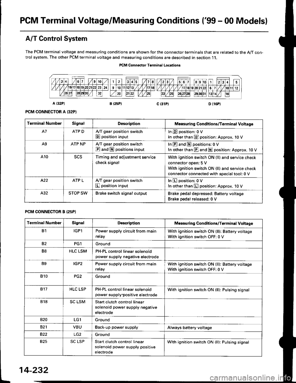
PGM Terminal Voltage/Measuring Conditions ('99 - 00 Modelsl
A/T Control System
The PCM terminal voltage and measuring conditions are shown for the connector terminals that are related to the A/T con-trol system. The other PCM terminal voltage and measuring conditions are described in section 11.
PICM Connoctor Terminrl Location3
Terminal NumberSignalDescriplionMeasuring Condhions/Torminal Voltage
A7ATP DA,/T gear position switch
E position input
InEposition:OV
In other than E] position: Approx. 1O V
A9ATP NPA/T gear position switch
@ and S positions input
In E and El positions: 0 V
In other than E] and E position: Approx. 1O V
A10Timing and adjustment service
check signal
With ignition switch ON {ll} and service check
connector oDen: 5 V
With ignition switch ON (ll) and service check
connector connected with soecialtool:0 v
ATP LA,/T gear position switch
I position input
In E position; OV
In other than E position: Approx. 10 V
STOP SWBrake switch signal outputBrake pedal depressed: Battery voltage
Brake pedal released: 0 V
PCM CONNECTOR B I25P}
Terminal NumberSignalDescriptionMoasuring Condhions/Terminal Vohage
B1IGPlPower supply circuit from main
relay
With ignition switch ON (lll: Battery voltage
With ignition switch OFF: 0 V
82PG1Ground
B8HLC LSMPH-PL control linear solenoidpower supply neqative electrode
B9IGP2Power supply circuit from main
relay
With ignition switch ON (lll: Battery voltage
With ignition switch OFF:0 V
810PG2Ground
817HLC LSPPH-PL control linear solenoid
power supplypositive electrode
With ignition switch ON {ll): Pulsing signal
818SC LSMStart clutch control linear
solenoid power supply negative
electrode
s20LGIGround
821VBUBack-up power supplyAlways battery voltage
B22Ground
825SC LSPStan clutch control linear
solenoid power supply positive
electrode
With ignition switch ON (ll): Pulsing signal
t
14-232
Page 952 of 2189
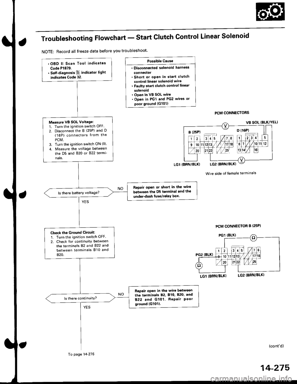
Troubleshooting Flowchart - Start
NOTE: Record all freeze data before you troubleshoot'
Clutch Control Linear Solenoid
PCM CONNECTORS
Wire side of lemale terminals
LGl (BRN/BLKI
(cont'd)
14-215
Po$ible Cause
. Disconnected solenoid harness
connedol. Short or open in sta.t clutch
control linear solenoid wiro. Faulty 3tart clutch conttol lin€ar
solenoid' Ooen in VB SOL wire. Open in PGI and PG2 wires or
poor ground {G101)
B l25P) -- o l16P)
'OBD ll Scan Tool indicates
Code Pl879.. self-diagnosis E indicstor light
indicates Code 32.
Measure VB SOL Voltag6:
1. Turn the ignition switch OFF
2. Disconnect the B {25P) and D(16P) connectors {rom the
PCM.3. Turn the ignition switch ON (ll).
4. Measure the voltage between
the D5 and 820 or 822 termi-
nals,
Reprir opon or short in the wire
between the D5 terminal and the
undei-d.sh luse/relaY box.ls there battery voltage?
Check the Ground Ciicuit:'1. Turn the ignition switch OFF.
2. Check for continuity between
the terminafs 82 and 922 and
between terminals 810 and
820.
Rep.ir open in the wire betwesn
the terminab 82, 810, 820. tnd
822 and G101. RePair Poorground lG101l.
ls there continuity?
LGl IBRN/BLK)
To page 14-276
PCM CONNECTOR B {25PI
Page 1281 of 2189
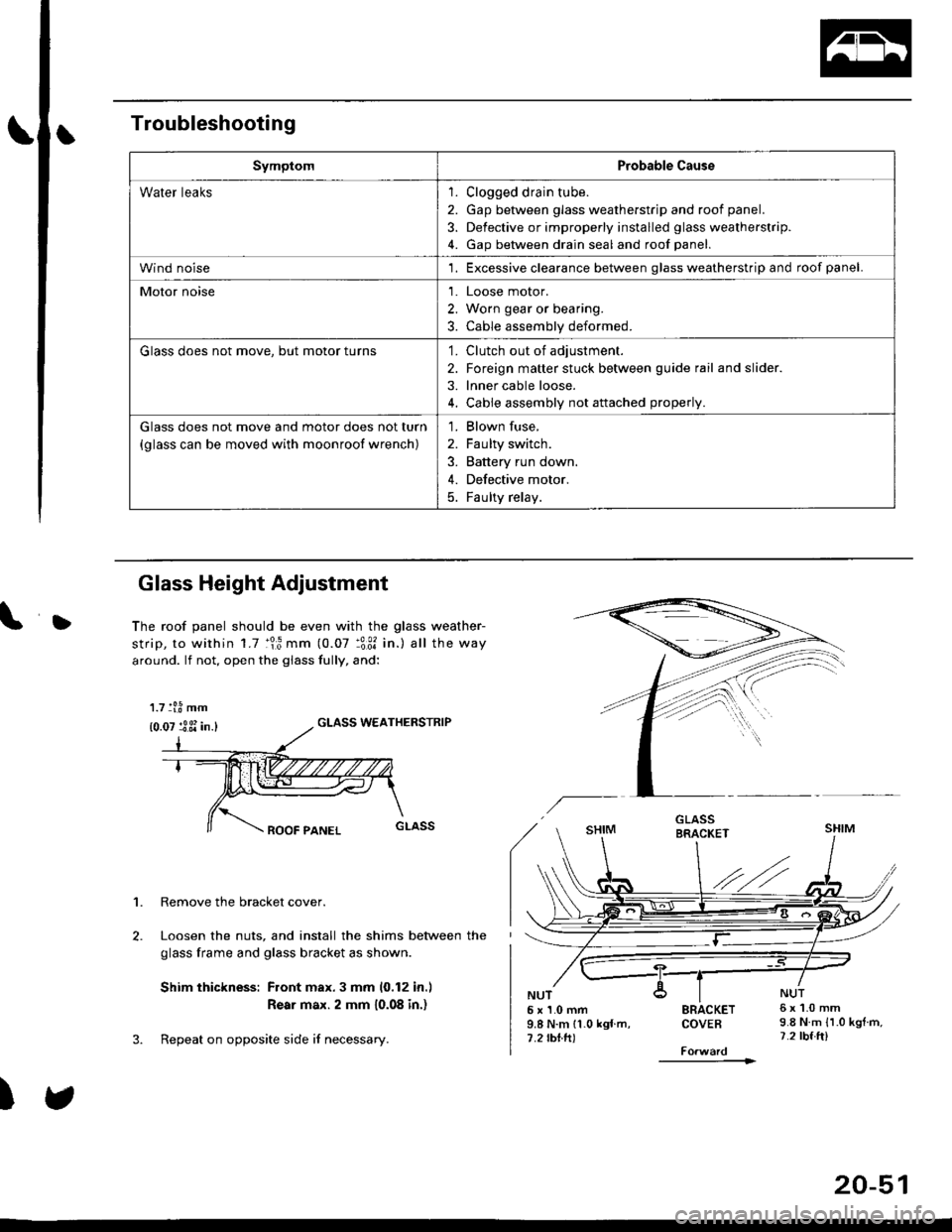
Troubleshooting
SymptomProbable Cause
Water leaks1. Clogged drain tube.
2. Gap between glass weatherstrjp and roof panel.
3. Defective or improperly installed glass weatherstrip.
4. Gap between drain seal and roof panel.
Wind noise'1. Excessive clearance between glass weatherstrip and roof panel.
Motor noise1. Loose motor.
2. Worn gear or bearing.
3. Cable assembly deformed.
Glass does not move, but motor turns'1. Clutch out of adjustment.
2. Foreign matter stuck between guide rail and slider.
3. lnner cable loose.
4. Cable assembly not attached properly.
Glass does not move and motor does not turn
{glass can be moved with moonroof wrench)
1. Blown fuse,
2. Faulty switch.
3. Battery run down.
4. Defective motor.
5. Faulty relay.
D
Glass Height Adjustment
The roof panel should be even with the glass weather-
strip, to within 1.7 :lr3 mm (0.07 :3:31 in.) all the way
around. lf not, open the giass fully, and:
GLASS WEATHERSTRIP
1. Remove the bracket cover.
Loosen the nuts, and install the shims between the
glass frame and glass bracket as shown.
Shim thickness: Front max.3 mm 10,12 in.l
Rear max. 2 mm 10.08 in.)
Repeat on opposite side i{ necessary.
)
5x1.0mm9.8 N.m 11.0 kgf m,7.2 rbtft)
SRACKETCOVEB
----------1>
6x1.0mm9.8 N.m {1.0 kgtm,7.2 tbf.ft)
1.7 tl.8 mm
{0.07 :3 3i in.}
20-51