1996 HONDA CIVIC Lock cylinder
[x] Cancel search: Lock cylinderPage 49 of 2189

MEASUREMENT
,n7 _--
STANDAFO INEW}
0.07 10.003) max.75.00 75.02 (2.953 - 2.954)
7 4.9A0 7 4.990 t2.9520 2.95241
0.010 - 0.040 (0.0004 0.0016)1.020 - 1.030 10.0402 _ 0.0406)1.220 1.230 (0.0480 - 0.0484)2.805 - 2.820 {0.1 104 _ 0.11 tO)
0.035 - 0.060 (0.0014 0.0024)0.030 - 0.055 {0.0012 0.0022)_
0.15 0.30 {0.006 _ 0.012)0.30 - 0.45 (0.012 - 0.018)0.20 - 0.70 10.008 0.028)
18.994 - 19.000 (0.7478 _ 0.7480)0.010 - 0 0?2 lo oona -n dn^ol
SERVICE LIMIT
0.10 (0.004)
75.07 (2.956)0.05 (0.002)0.5 (0.02)
74.970 (2.9516)
0.05 (0.002)1.05 (0.041)
1.2510.049)2.85 (0.112)
0.13 {0.005)0.13 (0.005)
0.60 (0.024)
0.70 (0.028)
ljqql) _
oro to.o',ur
0.005 (0.0002)
0.005 (0.0002)
0.4510.018)0.04 (0.002)
0.05 (0.002)
0.05 {0.002)0.05 (0.002)
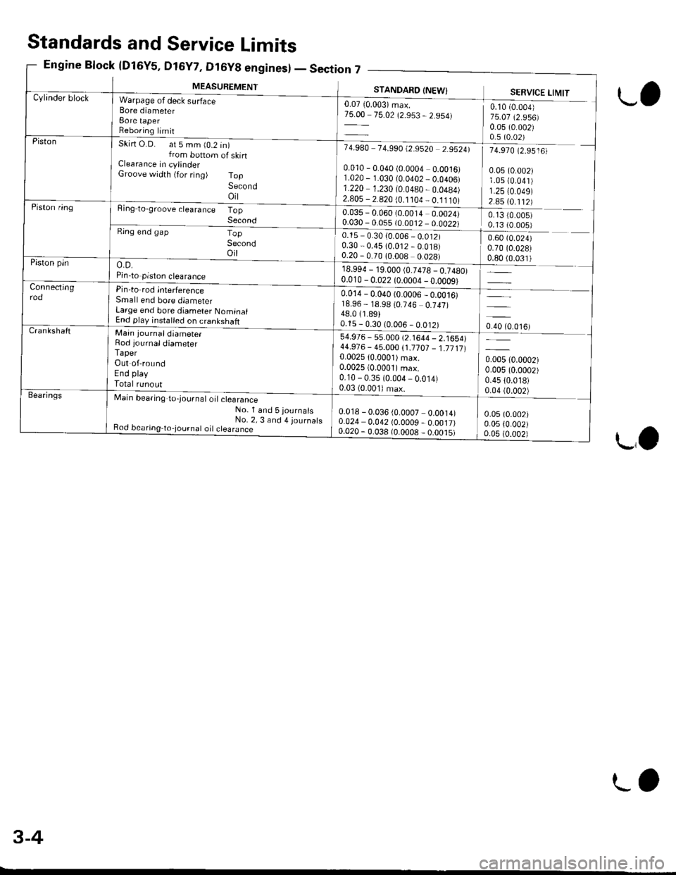
Cylinder blockWarpage of deck surfaceBore diameterBore taperReboring limit
Skirt O.D. at 5 mm (0.2 in)from bottom of skinClearance in cylinderGroove width {for ring) TopSecondoil
Ring to-groove clearance TopSecondRing end gapTopSecondoil
o.D.Pin-to piston clearance
Pin-to rod interferenceSmall end bore diameterLarge end bore diameter NominalEnd play installed on crankshaft
Piston
Piston ring
Piston pin
Connectingrod0.014 - 0.040 (0.0006 _ 0.ool6)18.96 - 18.98 (0.746 0.747)48.011.89)0.15 - 0.30 (0.006 - 0.012)CrankshaftMain journaldiameter
Rod iournaldiameterTaperOut of-roundEnd playTotal runout
Main bearing to-lournal o't clearance-No_ l and 5journals
_ No. 2, 3 and 4 journatsBod bearing to,journat oil ctearance
54.976 - s5.000 (2.1644 - 2.1654)44.91 6 - 45.000 1'1.17 01 _ 1.71 11 10.002510.0001) max.0.0025 (0.0001)max.
0.10 - 0.35 (0.004 0.014)0.03 (0.001) max.Bea.ings
0.018 - 0.036 (0.0007 0.0014)0.024 0.042 (0.0009 - 0.0017)0.020 - 0.038 (0.0008 _ o.oo.t5)
Standards and Service Limits
Engine Block {Dl6Y5, D16Y7, Dt6y8 enginesl - Section
L,
LO
3-4
LO
Page 50 of 2189

Section 7
Unlt of length: rnm ( n)
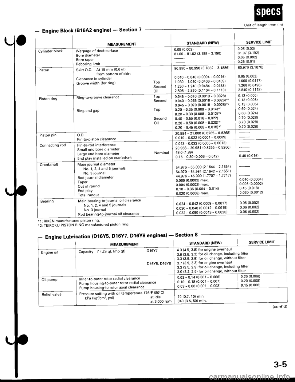
Engine Block(816A2 engine) -
MEASUREMENT
Warpage of deck surface
Bore diameterBore taperReboring limit
STANOARD {NEW)
0.05 (0.002)
8L00 81.02 (3.189 3.190)
SERVICE LIMIT
0.08 {0.03)81.07 (3.192)
0.05 (0.002)
0.25 (0.01)
Cylinder block
PistonSkin O D. At 15 mm (0.6 in)
{rom bottom of skirt
Clearance in cylinder
Groove width (for ring) ToPSecondoil
80.980 - 80.990 (3.lUUz 3. rUubl du Y/u lJ. ro/o,
I0.010 0.040 (o.ooo4 - 0.0016' 0 05 r0 002) II O3O 1.040 10.0406 - 0.04091 1 060 {0 0417) |1.230 - 1.?40 {0.0484 . 0.04881 1.260 10.04961 1'*: ?:::i?l:91'::ll:l I::::::= lPiston ringRing-to-groove clearance
Ring end gap
o.D.Pin to-piston clearance
Pin'to rod interference
Small end bore diameter
Large end bore diameterEnd play installed on crankshaft
Main journal diameterNo. 1, 2, 4 and 5 iournalsNo. 3 journal
Rod journal diameterTaperOut of roundEnd play
Total runout
Main bearing to_journal oil clearance
No. 1, 2, 4 and 5 journals
No. 3 journal
Bod bearing'to iournal oil clearance
Second
Top
Secondoil
Nominal
0.13 (0.005)
0.1310.005)0.60 (0.024)
0.60 t0.024)0.7010.028)0.70 (0.028)
,rr]q!4l
-l
u.u45 - u.u/u lu.uu ro
0.040 - 0.065 (0.0016 0.0026)*l
0.045 - 0.070 (0.0018 0.0028)*'
0.20 - 0.35 (0.008 - 0.014)*1
o.20 - 0.30 (0.008 - 0.012)*'�
0.40 0.55 (0.016 0.022)
0.20 - 0.50 (0.008 - 0.020)*'
0.20 - 0.45 (0.008 - 0.018)"
20.994 - 21.000 {0.8265 - 0.8268)
0.010 - 0.022 (0.0004 0.0009)
0.013 - 0.032 (0.0005 - 0.0013)
20.968 20.981 (0.8255 - 0.8260)
lliSlto?,o.oou o.o''r, o.rotoo'ut
Piston pin
Connecting rod
54.976 55.000 (2.1644 - 2.1654)
54.970 - 54.994 (2.1642 2.1651)
44.976 - 45.00011.'1707 - 1.1711|
0.005 (0.0002) max.0.004 (0.0002) max.0.10 0.35 (0.004 - 0.014)
0.020 (0.0008imax.
0.010 (0.0004)
0.006 (0.0002)
0.45 (0.018)
0.030 (0.0012)
Crankshaft
Eearing0.024 - 0.042 (0.0009 0.0017)
o.o3o - 0.048 {0.0012 0.0019)
0.032 - 0.050 (0.0013 - 0.0020)
0.06 (0.002)
0.06 (0.002)
0.06 (0.002)
*1: RIKEN manutactured prston rrng*2:TEIKOKU PISTON RING manufactured piston ring
gineslSection 8
(cont'd)
Engine Lubri,cation (Dl6Y5, Dl5Y7' Dl6Y8 enginesl -
MEASUREMENTSTANOARD (NEW) S€RVICE LIMIT
4.3 (4.5, 3.8)Ior engine overhaul
3.6 (3.8, 3.2) for oil change, including filter
3.3 (3.5, 2.9) for oil change, without filter
3.7 (3.9,3.3)for engine overhaul
3.3 (3.5, 2.9) for oil change, including filter
3.0 {3.2, 2.6} for oil change, without filter
0.02 - 0.14 (O.OO1 - 0.006) 0.20 {0 008)
0.10 0.18 (o.oo4 - 0.007) i 0.20 (0 008)
o 03 !.08 (qool!.oo3l _ (0 006) -
70 (0.7, 10) min.
340 (3.5,50) min
Engine oilCapacity | (US qt, lmp qt) D16Y7
D16Y5 D16Y8
lnner-to-outer rotor radial clearance
Pump housing to_outer rotor radialclearance
Pumo housrnq_to rotor a)rial clearance
Pressure setting with oil temperature 176'F (80'Ci
kPa (kgf/cm'�, PsiI at idleat 3,000 rpm
Oil pump
Relief valve
3-5
Page 65 of 2189

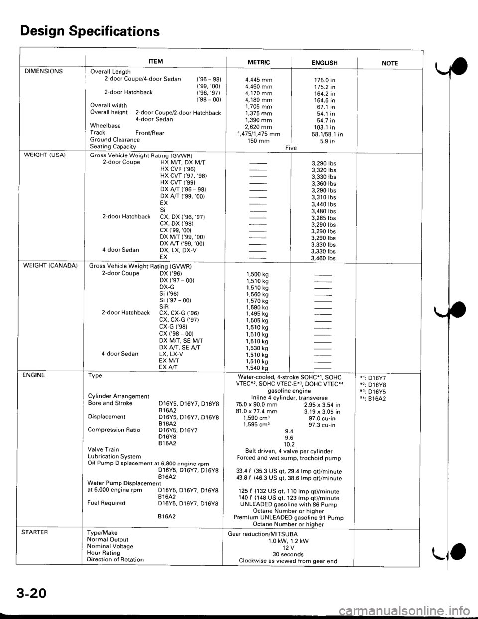
Design Specifications
ITEMMETRICENGLISHNOTEDII/IENSIONS Overall Length2 door Coupe/4 door Sedan (,96 98)('99,'�00)2 door Hatchback (,96, ,97)
('98 - 00)OverallwidthOverall height 2 door Coupe/2 door Hatchback4-door SedanWheelbase
I Track FronvRearGround ClearanceSeatiog Capacity
4,445 mm4,450 mm4,170 mm4,180 mm1,705 mm1,375 mm1,390 mm2,620 mm1,475/1,415 mm150 mm
175.0 in115.2 in164.2 in164.6 in67.1 in54.1 in54.7 in103.1 in58.1/58.15.9 in
WEIGHT (USA)Gross Vehicle Weight Raring (GVWR)2 door Coupe HX M/T, DX M/THX CVI ('96)HX CVT ('97,'98)HX CVT ('99}DX A,/T (96 98,DX A"/T ('99, '00)
EXSi2 door Hatchbacl CX. DX r'96, 97,cx, DX ('98)cx (,99, ,00)
DXM/Ti'99,00iDX A/T ( 99, 00,4 door Sedan DX, LX, DX-VEX
3,290 tbs3,320 tbs3,330 tbs3,360 rbs3,290 rbs3,310 tbs3,440 tbs3,480 tbs3,285 tbs3,290 tbs3,290 tbs3,290 tbs3,330lbs3,330 tbs3,460 tbsWEIGHT (CANADA)Gross Vehicle Weight Bating (GVWR)2-door Coupe DX ('96)DX ('97 00)DX-Gsi 1,96)si ('97 - 00)siR2 door Hatchback CX, CX,G ('96)cx, cx,G 1,97)cx-G (,98)
cx ('98 00)DX M/T, SE M/IDX A,/T, SE A,/T4 door Sedan LX, LX VEX M/IEX A/T
1,500 ks1,510 kg1,510 kg1,560 kg1,570 kg1,590 ks1,495 kg1,505 kg1,510 ks1,510 ks1,510 kg1,530 kg1,510 kg1,510 ks1,540 ksENGINEType
Cylinder ArrangementBore and Stroke D16Y5, D16Y7, Dt6y8B 1642DisplacementD16Y5, D16Y7, Dl6Y881642Compression Ratio D16Y5, D16y7D16Y8816A2Valve TrainLubrication SystemOil Pump Displacement at 6,800 engine rprnD16Y5, D,l6Y7, D16Y881642Water Pump Displacementat 6,000 engine rpm 016Y5, D16Y7, D16y8816A2Fuel Required D16Y5, D16Y7, D16y8
816A2
Water-cooled, 4-stroke SOHC*1, SOHCVTEC"', SOHC WEC.E'3, DOHC VTEC{gasoline engineInline 4 cylinder, transverse2.95 x 3.54 in3.19 x 3.05 in97.0 cu-in97.3 cu in9.49.610.2Belt driven, 4 valve per cylinderForced and wet sump, trochoid pump
33.4 f (35.3 US qt, 29.4 lmp qt)/minute43.8 | (46.3 US qt, 38.6 lmp qt)/minute
125 { {132 US qt, 110 lmp qt}/minute140 f {148 US qt, 123 lmp qt}/minuteUNLEADED gasoline with 86 PumpOctane Number or higherPremium UNLEADED gasoline 91 PumpOctane Number or higher
75.0 x 90.0 mm81.0 x 77.4 mm1,590 cm31,595 cm3
*1: D16Y7*': D16Y8*3: D16Y5*': 816A2
STARTEBType/MakeNormal OutputNominalVohageHour RatingDirection of Rotation
Gear reduction/MITSUBA1.0 kw, 1.2 kw12V30 secondsClockwise as viewed from gear end
5-Z.V
-
Page 100 of 2189

Engine Removal/lnstailation
Removal (cont'dl
Dl6Y5. DrGYr, D16Y8 enginas:
-1. Remove the mounting bolt and lock bolt, thenremove the P/S pump belt and pump.
MOUNTING BOLT8 x 1.25 mm24 N.m {2.4 kgl.m, 17 tbf.ftl
LOCK BOLT8 x 1.25 mm24 N.m 12.4 kgf.m, 17 lbf.ftl
17. Loosen the idler pulley center nut and adjustingbolt, then remove the air conditioning (A[/C)compressor belt.
IDI.IR PULLEY CENTERNUT10 x 1.25 mma,l N.m {,1.5 kgt.m, 33 lbf.ft)
5-6
(
'18. Remove the ransmission ground cable and hosect8mo.
HOSE CLAMP6 x '1.0 mm
19. Remove the clutch slave cylinder and line/hoseassembty (M/T).
NOTE:
. Do not disconnectthe pipe/hose assembly.. Do not operate the clutch pedal once the slavecylind€r has been removed.o Take care not to bend the line.
6x1,0mm 8x1.2Smm11 N.m {1.1 kgt.m, 2a N.m t2.4 kgf.m,I tbf.ftl 17 tbf.ftl
8 x 1.25 mm2a N'm {2,4 kgt m,17 tbt.ftl
Page 123 of 2189

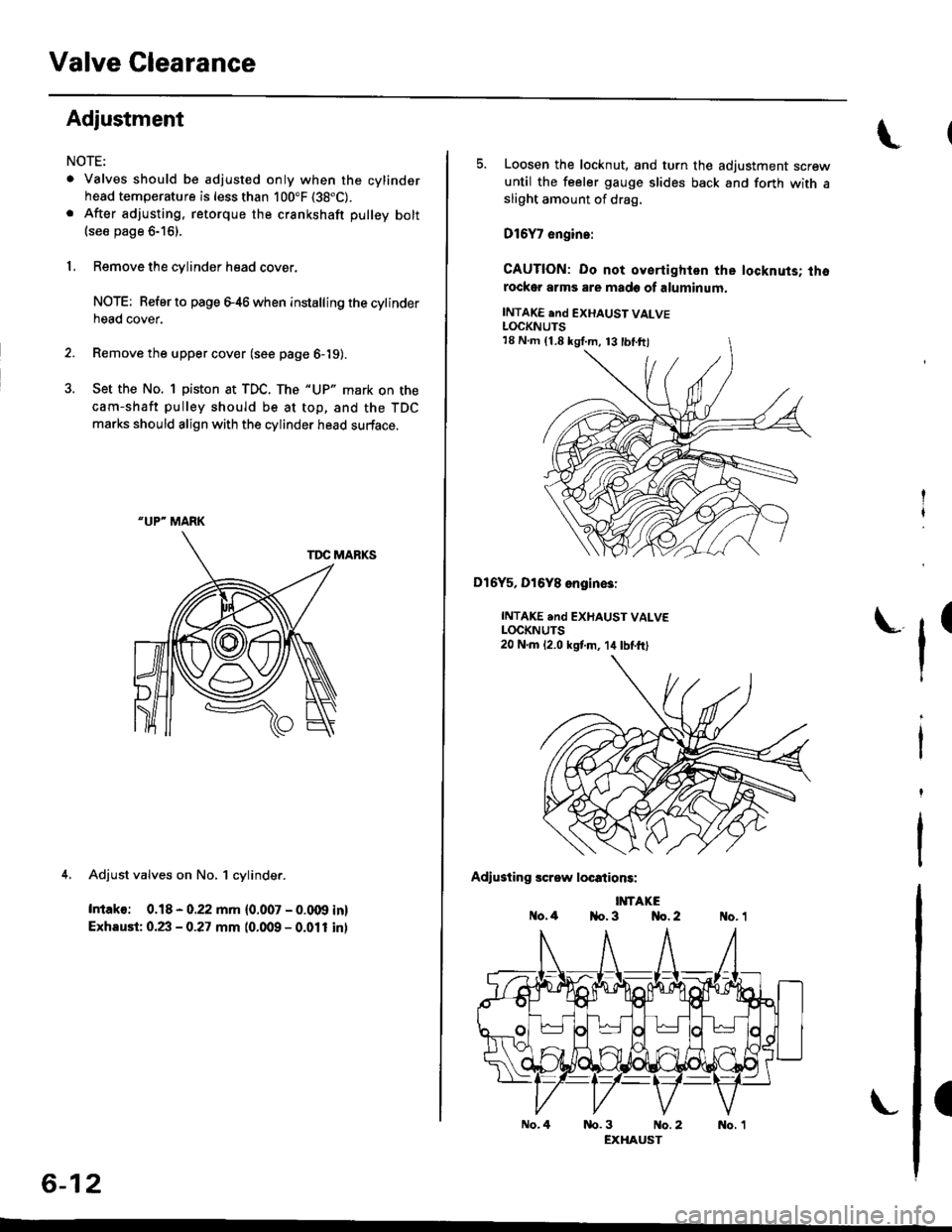
Valve Clearance
Adjustment
NOTE:
. Valves should be adjusted only when the cylindsrhead temperature is less than 100"F (38"C).
. After adjusting, retorque the crankshaft pulley bolt(see page 6-16).
1, Remove the cylinder head cover.
NOTE; Refer to page e46 when installing the cytinderhead cover.
2. Remove the upper cover (see page 6-19).
3. Set the No. 1 piston at TDC. The "UP" mark on the
cam-shaft pulley should be at top, and the TDC
marks should align with the cylinder head surface.
TDC MARKS
4. Adjust valves on No, 1 cylinder.
Intako: 0.18 - 0.22 mm {0.007 - 0.009 in}
Exhaust: 0.23 - 0.27 mm (0.009 - 0.011 inl
"UP" MARK
6-12
No.4
5. Loosen the locknut, and turn the adjustment screwuntil the feeler gauge slides back and forth with asliOht amount of drag,
D16Y7 engin.:
CAUTION: Do not oyertighlen the locknuts; thorockor arms are made of aluminum.
INTAKE end EXHAUST VALVELOCKNUTS
Dl6Y5, Dl6Y8 engin€3:
INTAKE .nd EXHAUST VALVELOCKNUTS20 N.m 12.0 kstm, 14lbtft)
Adiusting screw locations:
IMTAKEo.4 1{o. 3 No. 2
tr'
(
nb.3 No.2 No. 1EXHAUST
18 N.m (1.8 kgI.m, 13 tbl.ftl
Page 124 of 2189

6. Tighten the locknut, and check the clearance again.
Repeat the adjustment if necessary.
GAUGE
7.Rotate the crankshaft 180' counterclockwise (cam-
shaft oullev turns 90'1. The "UP" mark should be on
the exhaust side. Adjust valves on No. 3 cylinder.
"UP- MARK
t
8. Rotate the crankshaft '180' counterclockwise to
bring No.4 piston to TDC. Both TDC grooves are
once again visible. Adjust valves on No. 4 cylinder.
Rotate the crankshaft 180'counterclockwise to bring
No. 2 piston to TDC. The "UP" mark should be on
the intake side. Adjust valves on No. 2 cylinder.
-UP'MARK
6-13
Page 129 of 2189

Timing Belt
Inspection
1.
2.
3.
Remove the cylinder head cover.
. Refer to page 6 46 when installing.
Remove the upper cover (see page 6 19).
Inspect the timing belt for cracks and oil or coolantsoakrng.
NOTE:
. Replace the belt if oil or coolant soaKeo.. Remove any oil or solvent that gets on the belt.
Rotate pulleyand inspect belt.
After inspecting, retorque the crankshaft pullev bolt{see page 6- 16).
o- I6
Tension Adjustment
CAUTION: lt*ays aa;j"t the timing bett rension withthe engine cold.
NOTE:
. The tensioner is spring loaded to apply tension to thebelt automatically after making the following adjustment.
. Always rotate the crankshaft counterclockwise whenviewed from the pulley side. Rotating it clockwisemay result in improper adjustment of the belt ten-sion.
. lnspect the timing belt before adjusting the belt ten-ston.
1.Remove the cylinder head cover.
. Refer to page 6,46 when installing.
Remove the upper cover (see page 6,'19).
Rotate the crankshaft five or six revolutions to setthe belt.
Set the No. 'l piston at TDC (see page 6-21).
Loosen the adjusting bolt 180'.
2.
3.
4.
5.
\I
ADJUSTING BOLT44 N.m {4.5 kgt m,33 rbf.ft)
7.
8.
Rotate the crankshaft counterclockwise three teethon the camshaft pulley.
Tighten the adjusting bolt.
After inspecting, retorque the crankshaft pulley bolt(see page 6-16).
Page 138 of 2189

Removal
Engine removal is not required for this procedure
!!!s@ Make sure iacks and salety stands are
f ta"eata"ea propetty and hoist brackets are attached to the
correct positions on the engine.
CAUTION:
. Use tender covels to avoid damaging painted sul-
faces.
o To avoid damage, unplug the wiling connectors
carefully while holding the connector portion to
avoid damage.
. To avoid damaging the cylinder head, wait until the
engine coolant temperature drops below 100"F
{38"C} before loossning the tetaining bolts.
NOTE:
o Mark all wiring and hoses to avoid misconnectlon
Also, be sure that they do not contact other wiring or
hoses, or interfere with other parts.
. Inspect the timing belt before removing the cylinder
h ead.
. Turnthe crankshaft pu lley so that the No. lpistonisat
top dead center (see Page 6-21)
'1. Disconnect the negative terminal from the battery'
Drain the engine coolant (see page'10-7).
a Remove the radiator cap to speed draining.
Remove the intake air duct and air cleaner housing
(see page 5 3).
Remove the mounting bolt and lock bolt. then
remove the power steering (P/S) pump belt and
pump (see page 5'5).
Loosen the idler pulley center nut and adjusting
bolt' then remove the air conditioning (A'lc) com-
pressor belt (see Page 5-6).
Loosen the mounting nut and lock bolt. then
remove the alternator belt (see page 6-19).
Remove the P/S pump bracket (see page 5-12).
3.
4.
2.
6.
1.
8. Remove the throttle cable by loosening the locknut,
then slip the cable end out of the throttle linkage
NOTE:
. Take care not to bend the cable when removing it
Always replace any kinked cable with a new one
. Adjust the throttle cable when installing (see sec-
tion 1 1).
D16Y7 engine:
Dl6Y5, Dl6Y8 engines:
THFOTTLECABLE
(cont'd)
6-27
LOCKNUT
CABLE