Page 911 of 2189
Troubleshooting Procedures
l. How To Begin Troubleshooting
When the E indicator light has been reported on, use the appropriate procedure below to diagnose and repatr theproDlem.
A. When the @ indicator light has come on:
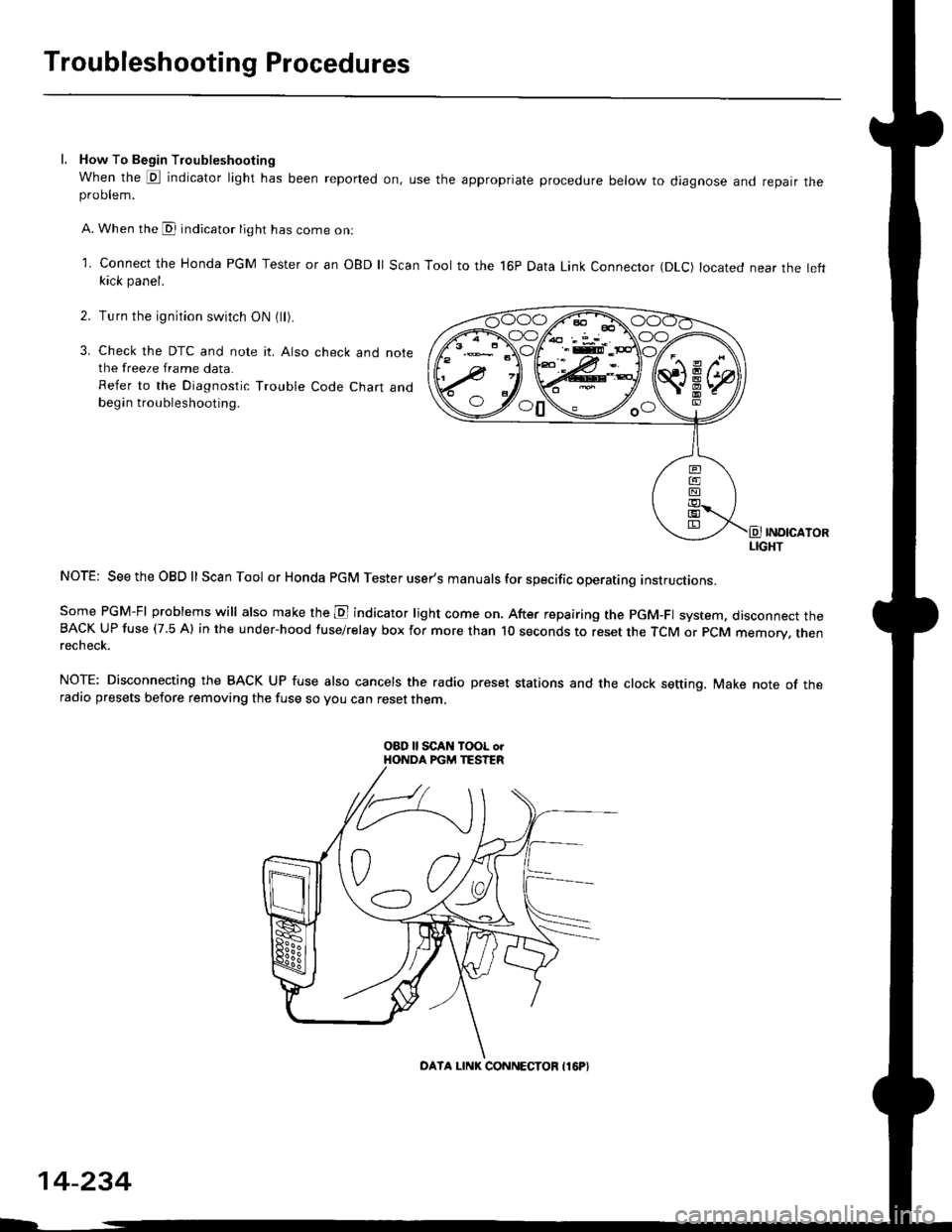
l connect the Honda PGM Tester or an oBD ll Scan Tool to the 16P Data Link Connector (DLc) located near the leftkick panel.
Turn the ignition switch ON (ll).
Check the DTC and note it. Also check and notethe freeze frame data.
Refer to the Diagnostic Trouble Code Chart andbegin troubleshooting.
INOICATORLIGHT
NOTE: SeetheOBDll Scan Tool or Honda PGM Tester user's manuals for specific operating instructions.
Some PGM-FI problems will also make the E indicator light come on. After repairing the pGM-Fl system, disconnect theBACK UP fuse (7.5 Al in the under-hood fuse/relay box for more than l0 seconds to reset the TCM or PCM memory, rnenrecheck.
NOTE: Disconnecting the BACK UP fuse also cancels the radio preset stations and the clock setting. Make note of theradio presets before removing the fuse so you can reset them,
2.
3.
o0\e--loo
OATA LINK CONNECTOB I16P}
14-234
Page 914 of 2189
ll. TCM Reset Plocedure
1. Turn the ignition switch off.
2. Remove the BACK Up fuse (7.5 A) from the under-hood fuse/relay box for 10 seconds to reset the TCM or PCM.
NOTE:
. Disconnecting the BACK UPfuse also cancelsthe radio preset stations and the clock setting Make nole ofthe radio
presets before removing the fuse so you can reset them
BACK UPt7.s Al FusE
. The TCM or PCM can also be cleared by using the OBD ll Scan Tool or Honda PGM Tester'
DATA LINK CONNECTOR {16PI
lll. Final Procedut€
NOTE: This procedure must be done after any troubleshooting
'1. Turn the ignition switch off.
2. Reset the TcM or PCM.
3. Disconnect the OBD ll Scan Tool or Honda PGM Tester from the Data Link Connector (16P), or remove the special tool
from the Service Check Connector.
4. Turn the ignition switch ON (ll), and set the radio presets and clock setting.
OBD ll SCAN TOOL o.PGM TESTER
14-237
Page 1070 of 2189
Steering Gearbox
Installation (cont'dl
Center the cable reel by first rotating it clockwise
until it stops. Then rotate it counterclockwise(approximately two turns) until the arrow mark on
the label points straight up. Reinstall the steering
wheel (see page 17-35).
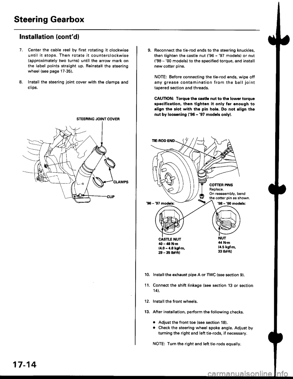
Install the steering joint cov€r with the clamps and
clrps.
7.
STEERING JOINI COVER
17-14
9. Reconnsct the ti€-rod ends to the steering knuckles,
thon tightsn th€ castle nut ('96 -'97 models) or nut('98 -'00 models) to the specified torque, and install
new cotter pins.
NOTE: Before connecting the tie-rod ends, wipe off
any grease contamination from the ball joint
tapered section and threads.
CAUTION: Torque lhe ct3tle nut to thr lowsr torque
spocification, th€n tighton it only tar anough to
align the 3lot with tho pin hob. Do not align the
nut by loosening ('96 - '97 modcls onlyl.
TIE.ROD
COTTER PINSR6plac6.On rgassombly, b6nd
'96 - 37 model3:
cotter prn as shown.'98 - '00 modol3:
NUT4a N.m(4.5 kgf.m,33 lbr.ftl
CAST1T NUT,O - ilt N'm{4,0 - 4.8 kgf.m.29 - 35 tbtftl
10.Installthe exhaust pipe A or TWC (see section 9).
Connect the shift linkage (see section 13 or section
14).
Install the front wheels.
After installation, perform the following checks.
. Adjust the front toe (see section 18).. Check the steering wheel spoke angle. Adjust by
turning the right and left tie-rods, if necessary.
NOTE: Turn the right and left tie-rods equally.
ll.
Page 1091 of 2189
Steering Wheel
l,/
Removal
SRS components are located in this area Review the
SRS component locations, precautions, and procedures
in the SRS section (24) before performing repairs or ser-
vice.
NOTE: Before removing the steering wheel. align the
front wheels straight ahead.
1. Remove the driver's airbag assembly from the
steering wheel (see section 24)
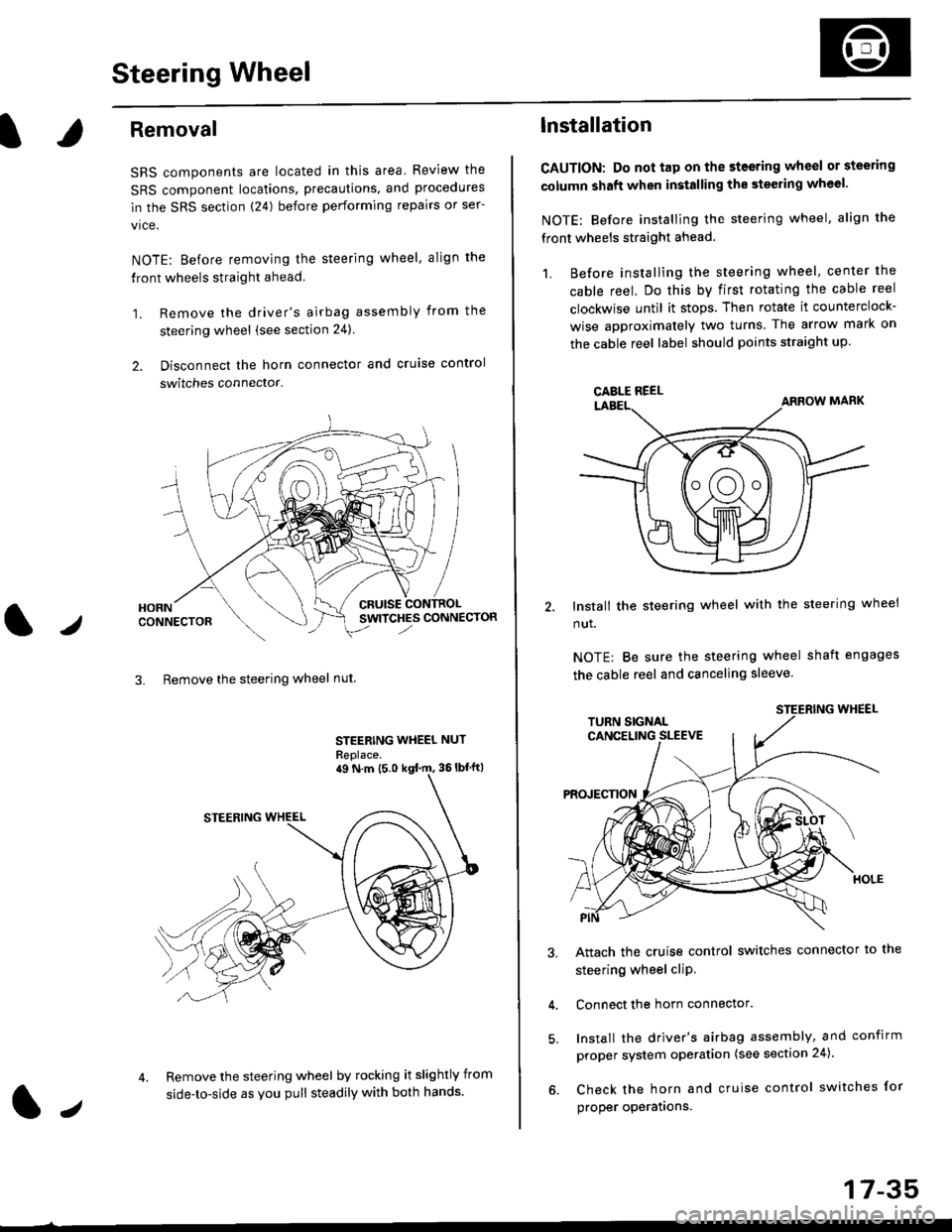
2. Disconnect the horn connector and cruise control
switches connector.
CRUISESWITCHES CONNECTOR
3. Remove the steering wheel nut
STEERING WHEEL NUT
Replace.
Remove the steering wheel by rocking it slightly from
side-to-side as you pull steadily with both hands.
ag N.m {5.0 kgt rn, 36lbfft)
1.,
17-35
lnstallation
CAUTION: Do not tap on the steering wheel or steering
column shaft when installing the stsering wheel.
NOTE: Before installing the steering wheel, align the
front wheels straight ahead.
1. Before installing the steering wheel, center the
cable reel, Do this by first rotating the cable reel
clockwise until it stops. Then rotate it counterclock-
wise approximately two turns The arrow mark on
the cable reel label should points straight up.
Install the steering wheel with the steering wheel
nut.
NOTE: Be sure the steering wheel shaft engages
the cable reel and canceling sleeve.
Attach the cruise control switches connector io the
steering wheel cliP,
Connect the horn connector.
Install the driver's airbag assembly, and confirm
proper system operation (see section 24).
Check the horn and cruise control switches for
proper operatrons.
CAELE REEL
Page 1122 of 2189
Steering Gearbox
Installation (cont'dl
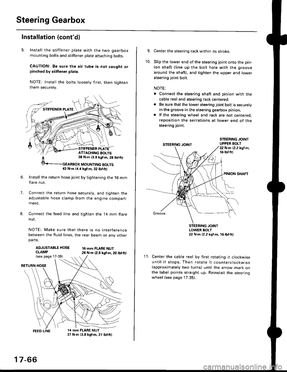
5. Install the stiffener plate with the two gearbox
mounting bolts and stiffener plate aftaching bolts.
CAUTION: Be sure the air tube is not caught orpinched by stiffener plate,
NOTE: Install the bolts loosely first, then tighten
them securely.
7.
8.
6.Install the return hose joint by tightening the l6 mm
flare nut.
Connect the relurn hose securely, and tighten the
adjustable hose clamp from the engine compart-ment.
Connect the feed line and tighten the 14 mm flare
nut.
NOTE: Make sure that there is no interference
between the fluid lines, the rear beam or any otherparts.
ADJUSTABLE HOSECLAMP(see page 17-39)
16 mm FLARE NUT28 N.m {2.9 ksl.m. 20 lbf.ft)
RETURN
1a mm FLARE NUT37 N.m (3.8 kg{.m, 27 lbt.ftl
ATTACHING AOLTS38 N.m 13.9 kgf.m, 28 lbf.ftl
MOUNTING BOLTS(} N.m (4.a kgt m, 32 lbf.ftl
17-66
9.Center the steering rack within its stroke.
Slip the lower end of the steering joint onto the pin-
ion shaft (line up the bolt hole with the groove
around the shaft), and tighten the upper and lower
steering joint bolt.
NOTE:
. Connect the steering shaft and pinion with the
cable reel and steering rack centered.. Be sure that the lower steering joint bolt is securely
in the groove in the steering gearbox pinion.
. lf the steering wheel and rack are not centered,
reposition the serrations at lower end of the
steering joint.
10.
STEERING JOINTUPPER BOLT22 N.m (2.2 kgf.m,16 tbt.ftl
PINION SHAFT
Groove,
STEERING JOINTLOWER BOLT22 N.m (2.2 kgt.m, 16lbtttl
11.Center the cable reel by first rotating it clockwise
until it stops. Then rotate it counterclockwise(approximately two turns) until the arrow mark onthe label points straight up. Reinstall the steeringwheel (see page 17 35).
Page 1179 of 2189
I
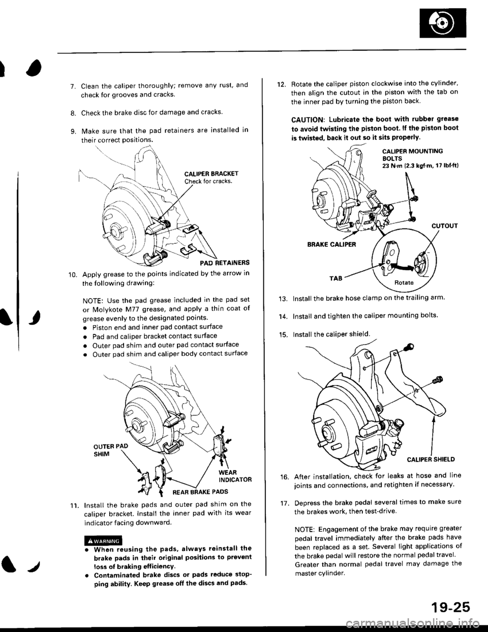
7.
11.
Clean the caliper thoroughly; remove any rust, and
check for grooves and cracks.
Check the brake disc for damage and cracks.
lvlake sure that the pad retainers are installed in
their correct positions.
PAD RETAINERS
Apply grease to the points indicated by the arrow in
the following drawing:
NOTE: Use the pad grease included in the pad set
or lMolykote M77 grease, and apply a thin coat of
grease evenly to the designated points.
. Piston end and inner pad contact surface
. Pad and caliper bracket contact surface
. Outer pad shim and outer pad contact surface
. Outer pad shim and caliper body contact surface
lnstall the brake pads and outer pad shim on the
caliper bracket. Install the inner pad with its wear
indicator facing downward.
@iwhen reusing the pads, always reinstall the
brake pads in iheil original posiiions lo prevont
loss ol braking efficiency
. Contaminaled brake discs or pads reduce stop-
ping ability. Keep grease off the discs and pads.
t./
19-25
12. Rotate the caliper piston clockwise into the cylinder'
then align the cutout in the piston with the tab on
the inner pad by turning the piston back
CAUTION: Lubricate ths boot with rubber grease
to avoid twisting the piston boot. lf the piston boot
is twisted, back it out so it sits properly.
CALIP€R MOUNTINGBOLTS23 N,m {2.3 kg{.m, 17 lbt'ft)
13.
14.
15.
CUTOUT
BRAKE CALIPER
Install the brake hose clamp on the trailing arm.
Install and tighten the caliper mounting bolts.
Install the caliper shield.
After installation. check for leaks at hose and line
joints and connections, and retighten if necessary.
Depress the brake pedal several times to make sure
the brakes work, then test-drive
NOTE: Engagement of the brake may requrre greater
pedal travel immediately after the brake pads have
been replaced as a set. Several light applications of
the brake pedal will restore the normal pedal travel.
Greater than normal pedal travel may damage the
master cylinder.
16.
17.
Page 1182 of 2189
Rear Brake Galiper
Disassembly (cont'd)
7. Remove the piston by rotating the piston counter-clockwise with the tool, and remove the piston
boot.
CAUTION: Avoid damaging the piston.
PISTON BOOTReplace.
Remove the piston seal.
CAUTION: Take care not to damage the cylinderbore.
CALIPER BODYCheck for scoring on
9. Install the special tool between the caliper bodv andspnng cover.
CAUTION: Be caretul not to damags the inside ofthe caliper cylinder during caliper disassembty.
BRAKE SPRINGCOMPRESSOR07HAE - SG00100
11.
LOCKNUTS
Position the locknuts as shown. then turn the shaftuntil the plate just contacts the caliper body.
NOTE: Do not compress the spring under thespring cover.
Turn the shaft clockwise 1/4 -'ll2 tu.n to comoressadjusting spring B in the caliper body.
CAUTION: To preyant damage to the inner compo-nonts. do not turn the shaft mor€ than 1/2 turn.
SHAFT
LOCKNUTS
PISTON SEALReplace.
ADJUSTII{GSPRING 8
19-28
Page 1183 of 2189
\
13.
Lower the locknuts fully, and tighten them securely.
NOTE: Keep the locknuts in this position until you
reinstallthe circlip.
Remove the circlip with snap ring pliers.
SNAP RINGPLIERS07914 - SA50001
't 4.Hold the plate with your fingers, and turn the shaft
counterclockwise. Remove the special tool from the
calioer.
LOCKNUTS
l./
15. Remove the adjusting bolt.
Remove the spring cover, adjusting spring B, spacer,
bearing A, and cup from the adjusting bolt.
Remove the sleeve piston, and remove the pin from
the cam in the caliper body.
'17 .
SLEEVE PISTONCheck lor wear anddamage,
i
I
I
6-50-awl \
IO-RIITGRepl6ce.
(cont'd)
19-29