Page 791 of 2189

Road Test
NOTE: Warm up the engine to normal operating tem peratu re (the rad iator fan comes on )'
1. Apply parking brake and block the wheels. Start the engine, then shift to E position while depressing the brake
Dedal, Depress the accelerator pedal and release it suddenly. The engine should not stall'
2. Repeat same test in E Position.
3. Test-drive the vehicle on a flat road in the E position. Check that the shift points occur at approximate speeds shown
in the table. Also check for abnormal noise and clutch slippage.
NOTE: Throttle position sensor voltage represents the throttle opening
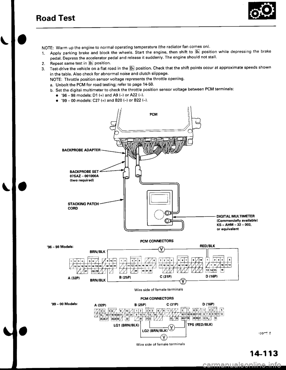
a. Unbolt the PCM for road testing; refer to page 14-50.
b. Setthedigital multimeter to check the th rottle position sensor voltage between PCM terminals;
. '96 - 98 models: D1 {+) and A9 (-) or 422 (-}.
. '99 - 00 models: C27 (+) andB20t-) orB22{-}.
BACKPROBE ADAPTER
BACKPROBE SET07sAz - 001oq)A{two requiredl
DIGIIAL MULTIMETERlCommercially available)KS-AHM-32-003,or equivalenl
'96 - 98 Modelsr
Wire side ol temale terminals
PCM CONNECTORS
B t25Pl c (31P)
LG1 IBRN/BLK)
I (25P1c (31P}
A t32PtD (16P)
Wire side ol female terminals
'9!t - 00 Models:
1+113
Page 793 of 2189
Accelerate to about 35 mph (57 km/h) so the transmlssion is in 4th, then shift from Dl position to Z position The
vehicle should immediately begin slowing down from engine braking'
CAUTION: Do not shift from -91 or -Dd position to E position at speeds ov6r 63 mph {100 km/hl; You mav damage
the transmission.
Check for abnormal noise and clutch slippage in the following positions'
E (2nd Gear) Position
ll Accelerate from a stop at full throttle. check that there is no abnormal noise or clutch slippage.
b. Upshifts and downshifts should not occur with the selector in this posirion'
E (Reverse) Position
i"ccelerate from a stop at fullthrottle, and check for abnormal noise and clutch slippage'
Test in B (Park) Position
Park the vehicle on slope (approx. l6'), apply the parking brake' and shift into E position Belease the brake; the veh'
cle shou,d nol move
1+115
Page 794 of 2189

Stall Speed
Test
CAUTION:
. To prev€nt transmission damage, do not t6st stall speed for more than ro sgconds at a time.. Do not shift the levor while raising the engine speed.. Bo sule lo remove the pressure gauge betoro testing stall speed.
'1. Engage the parking brake, and block the front wheels.
2. Connect a tachometer to the engine, and start the engine.
3. Make sure the Ay'C switch is OFF.
4. After the engine has warmed up to normal operating temperature (the radiator fan comes on). shift into E position.
5. Fully depress the brake pedal and accelerator for 6 to g seconds, and note engine speed.
6. Allow two minutes for cooling, then repeat the test in @ and @ positions.
NOTE:
. Stall speed tests should be used for diagnostic purposes only,. Stall speed should be the same in o., E and E positions.
Stall Spsed RPM:
Specification: 2.700 rpm
Service Limit: 2,550 - 2,850 rDm
TROUBLEPROBABLE CAUSE
. Low fluid level or ATF pump outDur. Clogged ATF strainer. Pressure regulator valve sluck closeo. Slipping clutch
. Slippage of 4th ctutch
. Slippage of 2nd clutch
. Slippage of lst clut"tr or. t"t g""io*-*"y "lut"h
Stall rpm high in D., E and E positions
Stall rpm high in El position
Stall rpm high in E posirion
Stall rpm high in E position
Stall rpm low in LDa . El and E positrons. Engine output low. Torque converter one-way clutch slipping
14-116
Page 796 of 2189
Fluid Level
Changing
NOT€: Keep all foreign particles out of the transmis-sion.
'1.Bring the transmission up to operating temperature(the radiator fan comes on) by driving the vehicle.
Park the vehicle on the level ground, and turn theengine off.
Remove the drain plug. and drain the automatictransmission fluid (ATF).
NOTE: lf a cooler flusher is to be used, see page 14-187 and 14-188.
TRANSMISgION END OOVER
DNAIN PLUG18 x 1.5 mm49 N.m (5.0 kgtm, 36lbf.ftlSEALING WASHERReplace.
Reinstall the drain plug with a new sealing washer,then refill the transmission with the recommended
fluid into the filler hole to the upper mark on thedipstick. Always use Genuine Honda premium
Formula Automatic Transmission Fluid (ATF). Usinga non-Honda ATF can aftect shift quality.
Automatic Transmission Fluid Capacity:
2.7 | |'2.9 US ql,2.a lmp qtl at Ghlnging
5.9 f 16.2 US qt. 5.2 lmp qt) at overhaul
I
14-11A
Page 820 of 2189
Main Valve Body
Disassembly/lnspection/Reassembly
NOTE:
. Cleanall parts thoroughly in solvent or carburetor cleaner, and drywith compressed air. Blowoutall passages.. Replace the valve body as an assembly if any pans are worn or damaged.. Check all valves for free movement. lf anyfail toslidefreely, see Valve Body Repairon page,l4-139.. Coat all parts with ATF during assembly.
CAUTION: Do not use a magnet to removs tha check balls; it may magnetizo the balls.
CPB VALVEVALVE CAP CLIP
ORIFICE CONTROL VALVE
BALLS, 8
lST ACCUMULATOR CHOKE
MODULATORVALVE
RELIEF VALVEVALVE
MAIN VALVE EODYInspect for wear, scratchesand scoring.
SEBVO CONTROL VAL
I.2 SHIFT VALVE
14-142
VALVE CAP
Page 822 of 2189

Secondary Valve Body
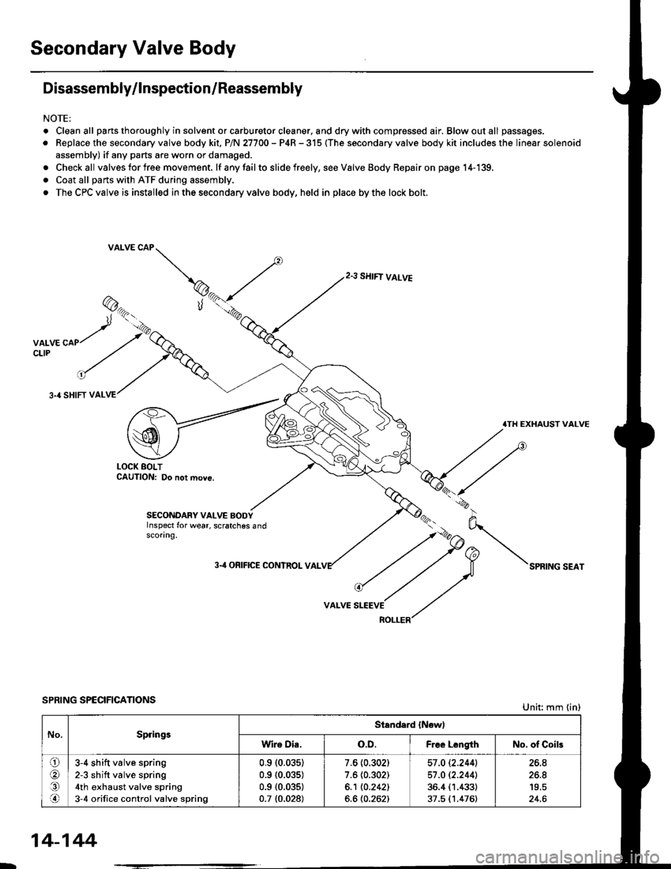
Disassembly/lnspection/Reassembly
NOTE:
. Cleanall parts thoroughly in solvent or carburetor cleaner. and drywith compressed air, Blowoutall passages.
. Replace the secondary valve body kit. P/N 27700 - P4R - 315 (The secondary valve body kit includes the linear solenoid
assembly) if any parts are worn or damaged.
. Checkall valves for free movement. lf anyfailto slide freely, seeValveBody Repairon page 14-139,
. Coat all parts with ATF during assembly.
. The CPC valve is installed in the secondary valve body, held in place by the lock bolt.
2.3 SHIFT VALVE
3.4 SHIFT VAL
.TH EXHAUST VALVE
LOCK BOLTCAUTION: Do not move.
SECONDARY VALVE BODYInspect for wear, scratches 6ndscoring.
3-'l ORIFICE CONTROL VAL
VALVE
SPRING SPECIFICATIONSUnit: mm (in)
No.SpringsStandard {New)
Wire Dia.o.D.Free LongthNo. of Coils
ora,.n
3-4 shift valve spring
2-3 sh ift valve spring
4th exhaust valve spring
3-4 orifice control valve spring
0.910.035)
0.9 {0.035)
0.9 {0.035)
0.7 {0.028)
7.6 (0.302)
7.6 (0.302)
6.1 10.2421
6.6 (0.262)
57 .O 12.2441
57 .O 12.2441
36.4 (1.433)
37.5 (1.476)
26.8
26.8
24.6
14-144
Page 823 of 2189

Regulator Valve Body
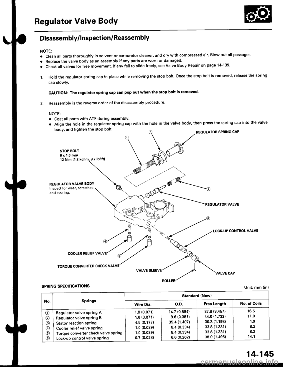
Disassembly/lnspection/Reassembly
NOTE:
. cleanall parts thoroughly in solvent or carburetor cleaner, and drywith compressed air. Blowoutall passages
. Replace the valve body as an assembly if any parts are worn or damaged.
. check allvalves for free movement. lf anyfail toslidetreely, see valve Body Repairon page 1+139.
1. Hold the regulator spring cap in place while removing the stop bolt. once the stop bolt is removed. release the spring
cap slowly.
CAUTION: The regulator 3pring cap can pop out when the stop boh is removod'
2. Reassembly is the reverse order ofths disassembly procedure.
NOTE:
o Coat all parts with ATF during assembly.
. Align the hole in the regulator spring cap with the hole in the valve body, then press the spring cap into the valve
body, and tighten the stop bolt.
STOP BOLT6x1.0mm12 N.m 11.28.7 tbf.lrl
^/^'ou*'oRsPRrNGcAP
*N@
REGULATOR VALVE
\=f -.-*
*fi /F { a-tLocK.uPcoNrRoLvALVE
cooLERRELlEFvALVr"r?
ry
roRouE coNvERrER cHEcKv ^LvE//
v ^r* "r**::f vi{LvE cAp
SPRING SPECIFICANONS
REGULATOR VALVE BODY
Inspect lor wear, scratches
and scorlng.
Unit: mm (in)
No,Springe
Standard (Now)
Wire Dia.o.D.Free LengrthNo. of Coils
o
o
@
@
@
Regulator valve sPring A
Regulator valve spring B
Stator reaction spring
Cooler relief valve spring
Torque converter check valve spring
Lock-up control valve sPring
1.8 {0.07'�r)
1.8 (0.071)
4.5 (0.177)
1.0 (0.039)
1.0 (0.039)
0.7 (0.028)
'r4.7 (0.584)
9.6 (0.381)
35.4 (1.407)
8.4 {0.334)
8.4 {0.334}
6.6 {0.262}
87.8 (3.457)
44.0 (1.732)
30.3 (1.193)
33.8 (1.331)
33.811.3311
38.0 {1.4961
11.0
1.9
8.2
a.2't 4.1
14-145
Page 825 of 2189
Lock-up Valve BodY
Disassembly/lnspection/Reassembly
NOTE:
. Clean all pans thoroughly in solvent or carburetor cleaner' and dry with compressed air' Blow out all passages'
a Replace the valve body as an assembly if any parts are worn or d€maged'
. Checkall valves for free movement ttanytaitio stlae freely' see Valve Body Repairon page 14-'139'
. Coat all parts with ATF during assembly
LOCK.UP VALVE BODY
Inspect for wear, scratchesand sconng.
VALVE CAP
LOCK-UP TIMING VAL
SPRING SPECIFICATIONSUnit: mm (in)
73.1 t2.902J
ao.7 13.'17717.6 (0.302)
8.1 (0.319)Lock-up shift valve sPrang
Lock-up timing valve sPrlng
14-147