1996 HONDA CIVIC 1 page
[x] Cancel search: 1 pagePage 774 of 2189
![HONDA CIVIC 1996 6.G Workshop Manual Electrical Troubleshooting (gg - 00 Models)
Troubleshooting Flowchart - Mainshaft Speed Sensor (cont,dl
Wire side of female terminals
PCM CONNECTOR D {16PI
23/)
618
rghrll [e]
NM IREDI
(
I
NMSG {WHTI HONDA CIVIC 1996 6.G Workshop Manual Electrical Troubleshooting (gg - 00 Models)
Troubleshooting Flowchart - Mainshaft Speed Sensor (cont,dl
Wire side of female terminals
PCM CONNECTOR D {16PI
23/)
618
rghrll [e]
NM IREDI
(
I
NMSG {WHTI](/manual-img/13/6068/w960_6068-773.png)
Electrical Troubleshooting ('gg - 00 Models)
Troubleshooting Flowchart - Mainshaft Speed Sensor (cont,dl
Wire side of female terminals
PCM CONNECTOR D {16PI
23/)
618
rghrll [e]
NM IREDI
(
I
NMSG {WHTI
(REDI
MAINSHAFT SPEEDSENSOR OONNECTORRED
Wire side of female terminals
NMSG IWHTI
From page l4-95
Measure Mainshatt SpeedSensor Resistance:1. Connect the mainshaft speedsensor connector.2. Measure the resistance bet-ween the Dl1 and D12 termi-nats.
Run the Electricel Troubl€shootingFlowchart lor cod6 m?m l9).Ch€ck lor loo.o te.minol fit in th6PCM connectors. lf necossary,substitute r known-good PCMend .echeck.
ls the resistance 400 - 600 0?
Check NM Wire Continuity:1. Disconnect the 2P connectorfrom the mainshaft speed sen-sor.2. Check for continuity betweenthe D11 terminal and the No. 2terminal ot the mainshaftspeed sensor connector,
Ropair opon in the wiro lratwoentho Dll tsrminal and tha main-3hatt spe€d sensor.
Check NMSG Wire Continuity:Check for continuity between theDl2 terminal and the No. 1 termi-nal of the mainshaft spoed sen-
Repai. open in the wire betwoenthe D12 terminal and the mein-shaft 3peod sansor.
Check Ior loose terminal fit in thePCM connectors. lf necesaary.substitute a known-good PCMand recheck.
1235
678
t1vNM
o
617 89ll12
Io
t1v
WHT
1
\
14-96
Page 775 of 2189
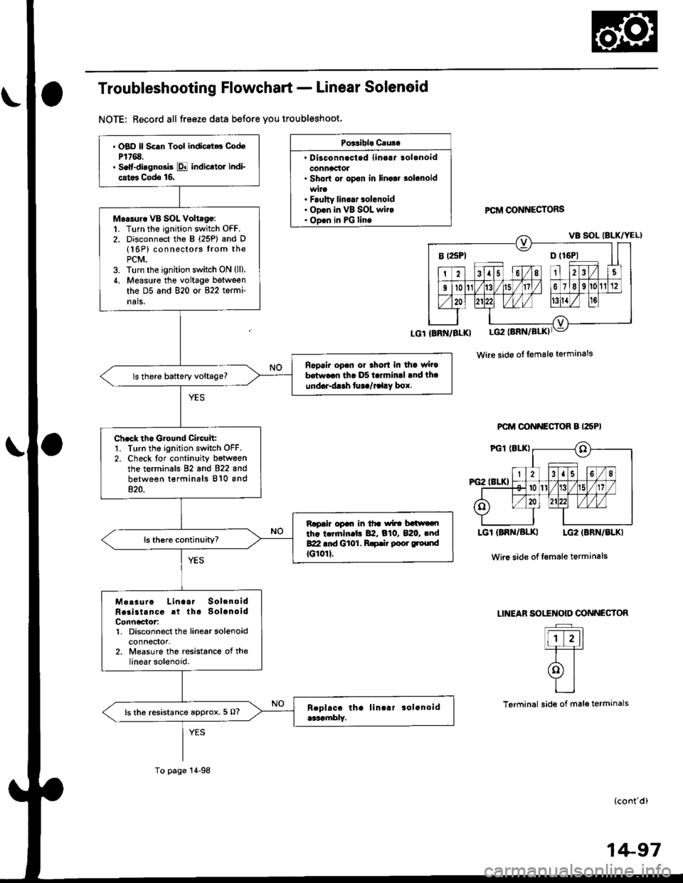
Troubleshooting Flowchart - Linear Solenoid
NOTE: Record all freeze data before you troubleshoot.
Poitibl. Cau3.
. Disconnacted linoaJ tolanoidconnaclol. Shorl or opon in linolr solonoid
. Flulty linoar 3olenoid. ODon in VB SOL wit.. ODen in PG linoPCftI @NNECTORS
Wire side ol female terminals
PCM OONNECTOR B I25PI
LGT (BNN/BLKI LG2 {BBN/BLKI
Wir6 side of Iemale terminals
LINEAF SOITNOID OONNECTOR
Flr-11=T=T
olYI
L_l
Terminal side of mal€ termanals
(cont'd)
B t25Pl D {16P1
. OBD ll Scln Tool indic.t.t CodoP1768.. Self-diagnosis E indicltol indi-
cat6 Cods 16.
Moasur. VB SOL Voltago:1. Turn the ignition switch OFF.2. Disconnect the B {25P) and D(16P) connectors from thePCM.3. Turn the ignition switch ON (lll.
4. Measure the voltage between
the D5 and 820 or 822 termi-
nals.
Ropair opan or thort in dla wi.9hrw..n th. D5 t.rminrl .nd th.
und.r-d.rh fu ta/r.l.y box.
Ch.ck th. Ground Circuit:1. Turn the ignition switch OFF.2. Check lor continuity betwoenthe terminals 82 and 822 and
between terminals 810 and820.
Rapair opal| in tfr wi|! batlwaoth. tcrrnln.l. 82, B10, B:20. .ndBZI .id Gt01. R.p.ir poor ground
tG10rl.
M.!sure Linea. SolenoidRcai3tancc rt tha SolanoidConn6ctor:1. Disconnect the linearsolenoidconnectol,2. Measure the resistance of thelinear solenoid.
ls the resistance approx. 5 O?
To page 14-98
1+97
Page 776 of 2189

Electrical Troubleshooting ('99 - 00 Modelsl
Troubleshooting Flowchart - Linear Solenoid (cont'dl
Check Linea. Solenoid tor aShort Ci.cuit:Check for continuity between thebody ground and the 88 terminaland B17 terminal individually.
PCM CONNECTOR A {25PI
Wire side of female terminals
From page 14 97
Repair shon in the wir6 betweenth€ 88 and 817 terminals and thelin€ar solenoid,
Measure Linear SolenoidResistance:1. Connect the linear solenoidconnector,2. Meas u re the resistancebetween the Bg and 817 termtnals,
Repair loose te.minal or open inthe wire botwoen the 88 .nd Bl7t.rmin.b end the linoar 3olenoid.
ls the resistance approx. 5.0 O?
Check for loose terminal tit in thePCM conn€ctors, lf necessary,substitut6 a known-good PCMand recheck.
LSAM (WHTI
14-98
Page 777 of 2189
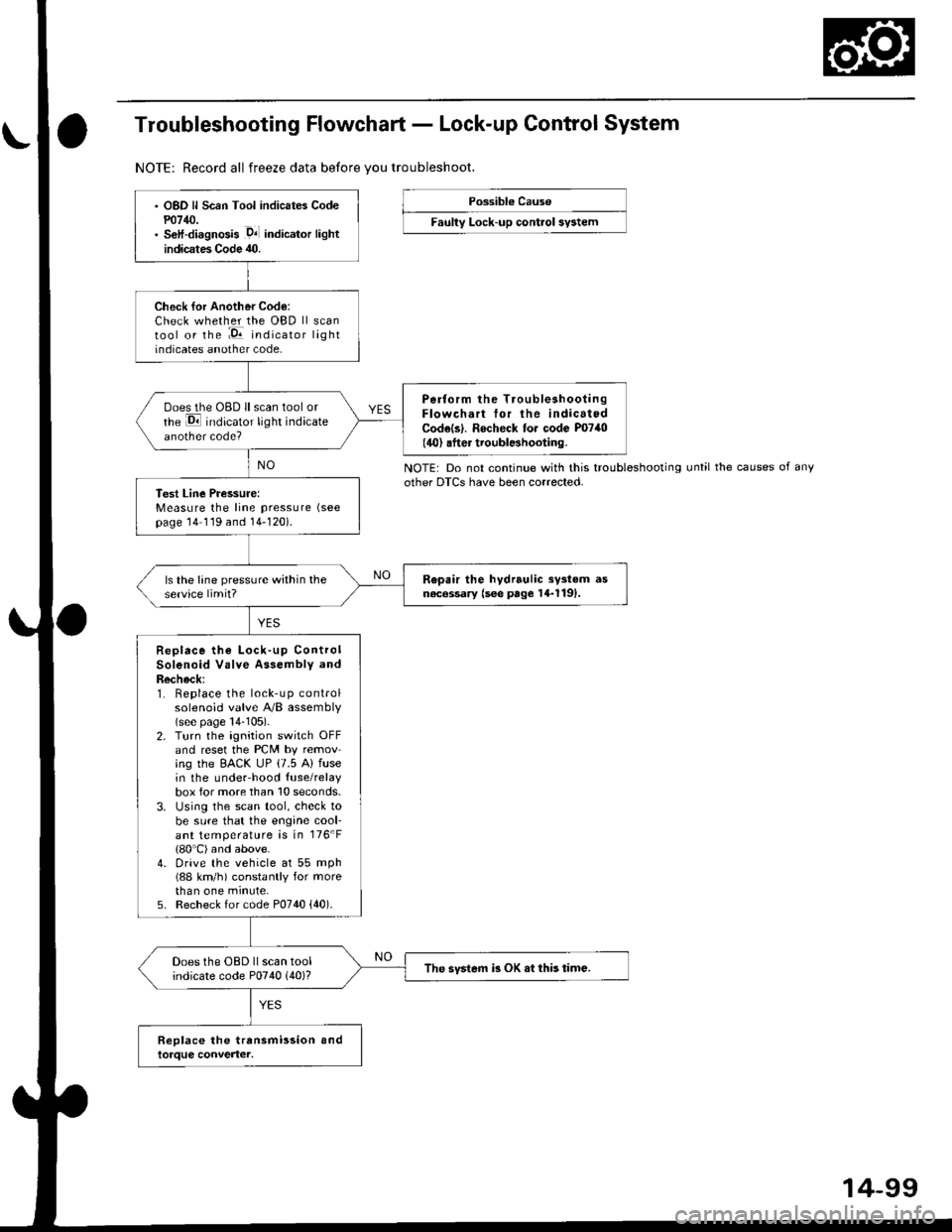
Troubleshooting Flowchart - Lock-up Control System
NOTE: Record all freeze data before vou troubleshoot.
Possibl€ Cause
Faulty Lock-up control sy3tem
NOTE: Do not continue with this troubleshootingother DTCS have been corrected.until the causes of any
OBD ll Scan Tool indicates Codem14/J.S€lf-diagnosis .D4l indicalor lightindicates Code 40.
Check for Another Code:Check whether the OBD ll scantool or the :E indicator lightindicates another code,
Perform the TroubleshootingFlowchart tor the indicatedCodels|. Rocheck to. code P0740(40) .fter troublBhooting.
ooes the OBD ll scan tool orrhe E indicator light indicateanother code?
Test Line Pressure:Measure the line pressure (see
page 14 119 and 14-120).
Repair the hydrrulic sy3tem asn6c6ssary (see page 14-1191.ls the lane pressure within theservice limit?
Replace the Lock-up ControlSolenoid Valve Assembly andRecheck:1. Replace the lock-up controlsolenoid valve A/B assembly(see page 14-105).2. Turn the ignition switch OFFand reset the PCM by removing the EACK UP (7.5 A) fusein the underhood {use/relaybox for more than 10 seconds.3. Using the scan tool, check tobe sure that the engine cool-ant temperature is in 176'F(80'C) and above.4. Drive the vehicle at 55 mph(88 km/h) constantly for morethan one minute,5. Recheck for code P0740 {40).
Does the OBD ll scan toolindicate code P0740 (40)?The svstem i3 OK .t this time.
14-99
Page 778 of 2189
Electrical Troubleshooting ('99 - 00 Modelsl
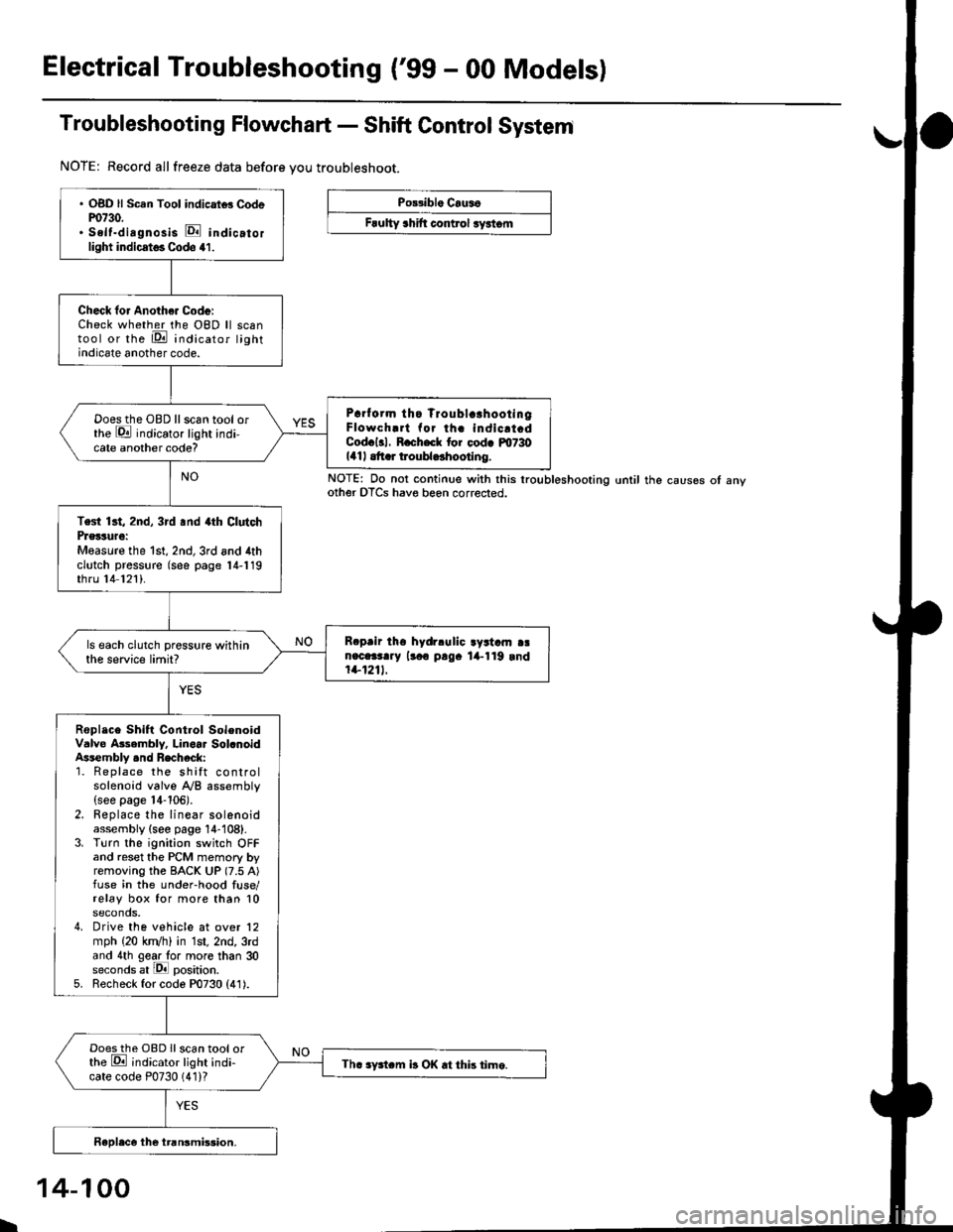
Troubleshooting Flowchart - Shift Control System
NOTE: Record allfreeze data before you troubleshoot.
Po33ibl. Crus6
Frulty 3hift control ryrtom
. OBD ll Scan Tool indicrtd Codem730.. Self-dirgnosis E indicatorlight indicst€. Codo 41.
Check for Anoth€. Code:Check whether the OBD ll scantool or the E indicator lightindicate another code.
Prrf orm tho Troublc!hootingFlowch.rt for th. indicrt.dCod.l3l. R.ch.ck tor cod. m730141| .tt r troubldhootlng.
Doesthe OBD llscan tool orthe E indicator light indi-cate another code?
Test 13t, 2nd, 3rd .nd 4th ClutchPrglture:Measure the 1st, 2nd,3rd and 4thclutch pressure (see page 14-119thru 14 121).
R.prir tho hydrlulic ayrtam aan.c.3t..y lr.o p!9. lil-119 rnd1+1211.
ls each clutch pressure withinthe service limit?
Roplace Shift Control SolenoidValve Asembly. Linoar Sol.noidAssembly .nd Recheck:1. Replace the shift controlsolenoid valve A/B assembly(see page 14-106).2. Replace the linear solenoidassembly {see page 14-108}.3. Turn the ignition switch OFFand reset the PCM memory byremoving the BACK UP (7.5 A)fuse in the under-hood fuse/relay box for more than 10seconds,4. Drive the vehicle at over 12mph (20 kn/h) in 1st, 2nd, 3rdand 4th gear lo. more than 30seconds at lPll position.5. Recheck for code P0730 (41).
Doesthe OBD Ilscan tool orthe E ;ndicator light indi-cate code P0730 (41)?Th. sFtcm b OK .t this time.
NOTE: Do not continue with this lroubleshooting until the causes ot anyother OTCS have beon corrected.
I
14-100
Page 780 of 2189

Electrical Troubleshooting ('99 - 00 Models)
Troubleshooting Flowchart - E Indicator Light Does Not Come On
FCM CONNECTOR B (25P}
LGl {8RN/ALKI{BRN/8LK}
Wire side ol temale terminals
LGl IBNN/BLK} LG2 {BRN/BLK)
i2t5 6q
910t7
LG2
o) (o
The Pll indicator light does notcome on when the ignitionswitch is fi.st turned ON (ll). lltshould come on for about twoseconda.l
Check the Service Check Con-nector:Make sure the special tool (SCS
Service Connector) is not connect-ed to the service check connector?
ls the specialtool {SCS ServiceConnector) is not connected tothe seNice check connector.
Disconnect the special tool fromthe service check connector andr6check.
Check the Dll lndicator LightiShift to d position.
Check for loose terminal fit in thePCM connecto13. It necessary.sub3titute a known-good PCMand recheck.
Does the @ indicator lightcome on?
Check the Ground Circuit:1. Turn the ignition switch OFF.2. Disconnect the B (25P) con-nector from the PCM.3. Check for continuity betweenthe 820 terminal and bodyground, and between the 822terminal and body ground.
Repair open in the wiresbetween the B20 rnd 822 termi-nals and ground (G101), andrep.ir poor ground (G1011.
Measure Power Supply CircuitVoltage:1. Turn the ignition switch ON {ll}.2. Measure the voltage betweenterminals B1 and 822 andbetween terminals Bg and820.
Repair open or short in the wi.obetween th6 81 and/or 89 termi-nals and the PGM-FI main relav,and between th€ PGM-FI mainr€ley rnd the under-hood tus€/relay box.
To page 14''103
14-102
Page 781 of 2189
From page 14-102
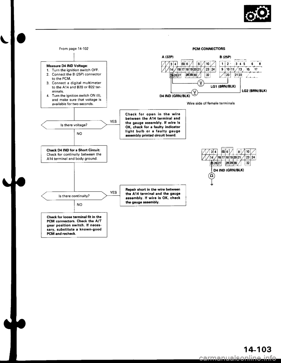
Measu.e D4 IND Voltago:1. Turn the ignition switch OFF.2. Connect the B (2SPiconnector
to the PCM.3. Connect a digital multimeter
to the A14 and 820 or 822 ter-
4. Turn the ignition switch ON (ll),
and make sure that voltage isavailable for two seconds.
Chock for ooon in tho witebetween the A't4 tsrminal .ndthe gauge.3s.mbly. ll wite i3OK, chock to. a t.ulty indicatorlight bulb or. feulty gaugc
e336mbly p.inted circuit board.
Check D4 IND lor a Short Citcuit:Check lor continuity between theA14 terminal and body ground.
Rop.ir short in thc wirg b€twoenth. Al4 tormin.l .nd tho gaugo
a$ombly. ll wiro is OK. chocktho gsugo a3rambly.
ls there continuity?
Check fo. loose terminal tit in thcPCM connectoB. Chock the A/Tgear position switch. It ncce3-sary, substitute a known-goodPCM and rechock.
PCM CONNECTORS
Wire side ol female terminals
14-103
Page 790 of 2189
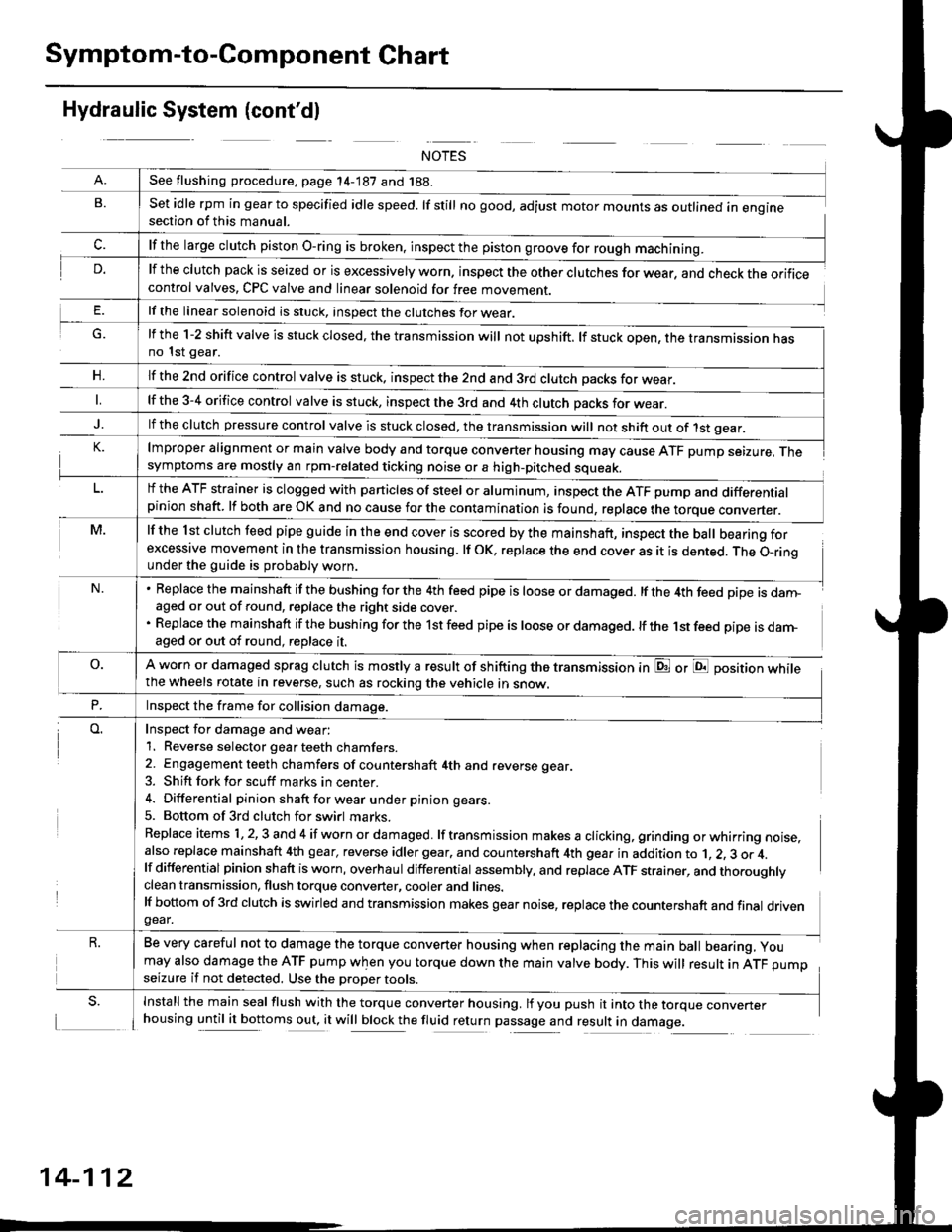
Symptom-to-Component Chart
Hydraulic System (cont'dl
G.
n,
set idle rpm in gear to specified idle speed. lf still no good, adjust motor mounts as outlined in enginesection of this manual.
lf the clutch pack is seized or is excessively worn. inspect the other clutches for wear, and check the orificecontrol valves, CPC valve and linear solenoid for free movement.
lf the linear solenoid is stuck, inspect the clutches for wear.
lmproper alignment or main valve body and torque converter housing may cause ATF pump seizure. Thesymptoms are mostly an rpm-related ticking noise or a high-pitched squeak.
lf the l st clutch feed pipe guide in the end cover is scored by the mainshaft, inspect the ball bearing forexcessive movement in the transmission housing. lf oK, replace the end cover as it is dented. The o-rinounder the guide is probably worn.
Replace the mainshaft if the bushing for the 4th feed pipe is loose or damaged. lf the 4th feed pipe is danFaged or out of round, replace the right side cover.
Replace the mainshaft if the bushing for the 1st feed pipe is loose or damaged. lf the 1st feed pipe is darn-aged or out of round, replace it.
A worn or damaged sprag clutch is mostly a result of shifting the transmission inthe wheels rotate in reverse, such as rocking the vehicle in snow.
or E position while
Inspect for damage and wear:
1. Reverse selector gear teeth chamfers.
2. Engagement teeth chamfers of countershaft 4th and reverse gear.
3. Shift fork for scuff marks in center.
4. Differential pinion shaft for wear u nder pin ion gears.
5. Bottom of 3rd clutch for swirl marks.
Replace items 1,2,3 and 4 if worn or damaged. lf transmission makes a clicking, grinding orwhirring noise,also replace mainshaft 4th gear, reverse idler gear. and countershaft 4th gear in addition to 1, 2, 3 or 4.lf differential pinion shaft is worn, overhaul differential assembly, and replace ATF strainer, and thoroughlyclean transmission, flush torque converter, cooler and lines.lf bottom of 3rd clutch is swirled and transmission makes gear noise, replace the countershaft and final drivengear.
Be very careful not to damage the torque converter housing when replacing the main ball bearing, you
may also damage the ATF pump when you torque down the main valve body. This will result in ATF pumpseizure if not detected. Use the oroper roors.
Install the main seal flush with the torque converter housing. lf you push it into the torque converterhousing until it bottoms out, it will block the fluid return passage and result in damage.
See flushing procedure, page 14-187 and 188.
lf the large clutch piston O-ring is broken, inspect the piston groove for rough machining.
lf the l-2 shift valve is stuck closed, the transmission will not upshift. lf stuck open, the transmission hasno 1st gear.
lf the znd orifice control valve is stuck. inspect the 2nd and 3rd clutch oacks for wear.
lf the 3-4 orifice control valve is stuck, inspect the 3rd and 4th clutch oacks for wear.
lf the clutch pressure control valve is stuck closed, the transmission will not shift out of 1st gear.
lf the ATF strainer is clogged with particles of steel or aluminum, inspect the ATF pump and differentialpinion shaft. lf both are OK and no cause for the contamination is found, replace the torque converter.
Inspect the frame for collision damage.
14-112